

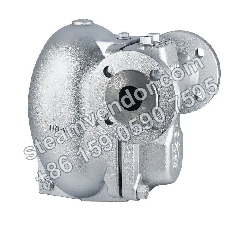
Gestra UNA25PK is a DN40, PN40 condensate lifter steam trap with DIN/ANSI flanged connections. Driven by motive steam, it provides continuous condensate drainage when sufficient differential pressure is available and switches to cyclic condensate lifting when the differential pressure is insufficient or back pressure is present. It withstands operating temperatures up to 350°C. The unit is designed for condensate lifting and discharge in steam systems and effectively addresses condensate accumulation under low-differential-pressure or high-back-pressure conditions.
Gestra condensate lifter UNA25PK, 3/4-inch angle product image
1 / 1
UNA25PK Condensate Lifter Steam Trap | Gestra
Motive steam operated condensate lifter with DN40 flanges; switches to lifting mode when the differential pressure is insufficient.
Genuine product assurance
We can help verify product data and purchasing details.
Model confirmation
Confirm model, connection and key options before ordering.
After-sales support
After-sales communication support is provided according to the order agreement.
Specifications
- Connection type
- DIN/ANSI flanges
- Nominal size
- DN40
- Pressure rating
- PN40
- Operating mode
- Continuous condensate drainage with sufficient differential pressure; cyclic condensate lifting when the differential pressure is insufficient or the upstream pressure is lower than the back pressure
- Drive method
- Motive steam drive
- Pressure-temperature rating
- 40.5 bar @ 20°C; 38.3 bar @ 120°C; 31.6 bar @ 250°C; 25.0 bar @ 350°C (EN 1092-2 PN40 flanges)
- Maximum motive steam pressure and differential pressure
- 6 bar (orifice 6) or 13 bar (orifice 13)
- Maximum operating back pressure
- 3 bar (orifice 6) or 5 bar (orifice 13)
- Minimum motive steam pressure
- 3 barg, and at least 1 bar higher than the back pressure
- Orifice flow coefficient
- Orifice 6: Kvs 3.5 m³/h, orifice diameter 11.0 mm; orifice 13: Kvs 2.1 m³/h, orifice diameter 8.5 mm
- Motive steam connection
- G½ female thread
- Vent connection
- G½ female thread
- Minimum filling height
- 0.5 m
- Inlet piping requirement
- Minimum length 2.5 m, DN40; or a buffer tank with a volume of 3 L
- Overall dimensions
- Overall length 230 mm (DIN/EN flanges); width 325 mm; height 318 mm; maintenance clearance 200 mm
Application scenarios
Condensate lifting and discharge in steam systems
In steam systems, UNA25PK uses motive steam to provide continuous condensate drainage or cyclic condensate lifting. When the differential pressure is insufficient or the upstream pressure is lower than the back pressure, condensate is discharged by cyclic lifting.
Installation & maintenance notes
Inlet piping and buffer volume requirements
The inlet piping should be DN40 with a minimum length of 2.5 m, or a buffer tank with a volume of 3 L should be installed to provide the inlet-side conditions required for condensate lifting operation.
Operating mode and minimum filling height
The unit provides continuous condensate drainage when sufficient differential pressure is available and cyclic condensate lifting when the differential pressure is insufficient. A minimum filling height of 0.5 m must be maintained during installation and operation.
Maintenance clearance requirements
At least 200 mm of maintenance clearance should be provided at the installation site to facilitate servicing and inspection.
FAQ
How does the UNA25PK work?
As a condensate lifter, the UNA25PK uses a float and rolling ball mechanism inside the valve body to discharge and pump condensate in stages. As condensate enters the body, the rising float actuates the closing element, opening the motive steam inlet and closing the vent valve, so the motive steam forces the condensate out of the body. Once the liquid level drops, the next cycle begins, providing continuous drainage with reduced steam loss.
How do I size the UNA25PK and confirm its operating parameters?
Sizing requires confirming the operating pressure, back pressure, orifice size, and the connection type of the flanged or threaded end. For the UNA25PK, the maximum differential pressure and flow rate at orifice 6, and their dependence on back pressure, must be assessed together with the upstream pressure, back pressure, and piping layout to determine the pumping capacity.
What are the main differences between the UNA25PK and the UNA25-PS?
The UNA25PK uses a closing mechanism with a rolling ball valve in its key components, operates in pumping mode, and can drain continuously within a certain differential pressure range. The UNA25-PS, by contrast, is a periodic condensate lifter without a valve closing mechanism and discharges continuously only when the upstream pressure is lower than the back pressure. Both are used to remove condensate from steam, but they differ in operating mode and pressure conditions.
What are the key points to observe for connection and installation?
The unit uses DIN/ANSI flanged connections, and the valve body is made of steel (1.0460). A motive steam line and a vent line must be provided and connected, and a minimum filling head of 0.5 m must be maintained between the condensate outlet and the bottom of the unit. An inlet line or buffer storage tank is also required to ensure stable circulation.
How can the pumping capacity and flow rate be evaluated in actual service?
Pumping capacity varies with differential pressure and filling head; the supplied charts must be adapted to the actual filling head (e.g. 1 m). The actual pumping capacity equals the chart value multiplied by the filling head correction factor. Where condensate must be lifted, the differential pressure decreases as the lifting height increases, so the assessment must account for the system piping and the density of the medium.