

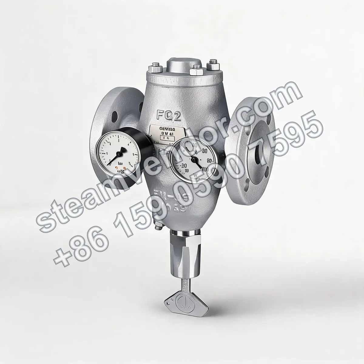
The Gestra CW41 cooling-water limiter is a direct-acting proportional temperature-controlled return-temperature control valve. The valve body is made of EN-GJS-400-18U-LT, with nominal sizes from DN25 to DN100 and a nominal pressure rating of PN16. A pressure gauge, thermometer, and adjustment key are supplied as standard. The valve regulates cooling-water flow according to the return temperature and is suitable for temperature control and flow limiting in industrial cooling-water or brine return lines.
Gestra Cooling Water Limiter CW41 product image
1 / 1
CW41 Cooling Water Temperature Control Flow Limiter Valve | Gestra
Direct-acting proportional temperature control valve that regulates cooling water flow based on return water temperature. Supplied as standard with a pressure gauge, thermometer, and adjustment key.
Genuine product assurance
We can help verify product data and purchasing details.
Model confirmation
Confirm model, connection and key options before ordering.
After-sales support
After-sales communication support is provided according to the order agreement.
Specifications
- Control principle
- Direct-acting proportional temperature control
- Applicable medium
- Industrial cooling water
- Installation line
- Cooling-water or brine return line
- Nominal sizes
- DN25, DN40, DN50, DN80, DN100
- Pressure rating
- PN16
- Maximum operating pressure
- 16 barg
- Maximum differential pressure
- 6 bar
- Connection
- DIN 2533 (BS 4505) PN16 Type C flanges; ASME 150 drilled flanges available as an option
- Valve body material
- EN-GJS-400-18U-LT (EN-JS 1049; previous designation GGG-40.3 / 0.7043)
- Adjustable outlet temperature
- w thermostat: 20–60°C; n thermostat: 3–100°C; k thermostat: -32 to +74°C
- Maximum permissible short-term temperature
- w thermostat: 100°C; n thermostat: 120°C; k thermostat: 85°C
- Temperature differential at full opening
- w thermostat: 9 K; n and k thermostats: 21 K
- Temperature hysteresis
- w thermostat: 1 K; n and k thermostats: 3 K
- Time constant
- w thermostat: 30 s; n and k thermostats: 60 s
- Flow coefficient Kvs
- DN25: r 2.1 m3/h, s 10.5 m3/h; DN40/50: r 6.5 m3/h, s 31 m3/h; DN80/100: r 20 m3/h, s 98 m3/h
- Relief flow coefficient Kvo
- DN25: r 0.12 m3/h, s 0.55 m3/h; DN40/50: r 0.31 m3/h, s 1.5 m3/h; DN80/100: r 1.0 m3/h, s 5.0 m3/h
- Standard equipment
- 0–6 bar pressure gauge, -30 to +100°C thermometer, detachable adjustment key
Application scenarios
Temperature control and flow limiting in industrial cooling-water return lines
The CW41 is suitable for industrial cooling-water return lines. It uses direct-acting proportional temperature control to regulate cooling-water flow according to the return temperature.
Low-temperature control and flow limiting in brine return lines
The CW41 is suitable for brine return lines and can be fitted with a k thermostat for temperature control and flow regulation within the range of -32 to +74°C.
Installation & maintenance notes
System pressure, differential pressure, and temperature limits
During operation and commissioning, verify that the operating pressure in the industrial cooling-water return line, the differential pressure across the valve, and the thermostat temperature are within the permissible ranges for the relevant CW41 configuration. The maximum operating pressure must not exceed 16 barg, the maximum differential pressure must not exceed 6 bar, and the maximum permissible short-term temperature must comply with the limits for the thermostat type: 100°C for type w, 120°C for type n, and 85°C for type k.
FAQ
How does the Gestra CW41 cooling-water temperature-controlled limiting valve automatically regulate flow according to the return temperature?
The CW41 uses direct-acting proportional temperature control and requires no external power supply or control signal. As the internal thermostat is heated, its volume changes and transmits the stroke to the double-seat valve plug through the adjustment mechanism. When the cooling-water outlet temperature rises, the valve plug moves in the opening direction against the spring force and increases the flow. When the temperature falls, the valve plug moves in the closing direction under spring force, maintaining the outlet temperature near the preset range.
Which cooling media and pipeline positions are suitable for the CW41?
The CW41 is suitable for industrial cooling-water return lines and can be installed in the cooling-water circuit of equipment such as heat exchangers to control cooling-water flow according to the return temperature. For ammonia water, brine, or chlorinated hydrocarbons, the applicable valve type is CW41/4. For brine applications, the valve can be equipped with a pressure gauge, thermometer, and an extension for the setting device.
How should the thermostat and valve plug combination be selected for the CW41?
Selection should be based on the required outlet temperature, actual temperature differential, differential pressure, and required flow rate or heat dissipation. For simplified selection by outlet temperature, the wr combination is suitable for 20–60°C, the nr combination for 50–100°C, and the kr combination for -32 to +30°C. The r valve plug is a reduced-diameter plug for lower flow rates, while the s valve plug is a standard plug for higher flow rates. If multiple nominal-size and valve-plug combinations are feasible, the valve plug with the lower relief flow rate should generally be selected.
What temperature adjustment ranges and control-response characteristics are available for the CW41?
The CW41 can be fitted with three thermostat types. Type w provides an adjustable outlet temperature of 20–60°C, a maximum permissible short-term temperature of 100°C, a temperature differential at full opening of 9 K, hysteresis of 1 K, and a time constant of 30 seconds. Type n provides 3–100°C, a maximum permissible short-term temperature of 120°C, a temperature differential at full opening of 21 K, hysteresis of 3 K, and a time constant of 60 seconds. Type k provides -32 to +74°C, a maximum permissible short-term temperature of 85°C, a temperature differential at full opening of 21 K, hysteresis of 3 K, and a time constant of 60 seconds. The actual system response time for reaching the set outlet temperature may range from 10 to 50 minutes.
What should be considered during CW41 installation and on-site adjustment?
The CW41 should be installed in the cooling-water return line, preferably close to the heat exchanger, and should preferably be arranged in a horizontal pipeline. During installation, position the adjustment key downward and use suitable piping to prevent the valve from draining. The valve is supplied as standard with a 0–6 bar pressure gauge, a -30 to +100°C thermometer, and a detachable adjustment key. After start-up, make adjustments gradually by turning the key by 1/4 to 1/2 turn at a time, while observing outlet-temperature changes on the thermometer.