

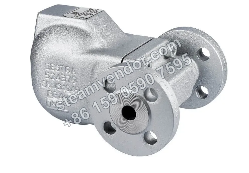
The Gestra UNA14P is a float-type trap with a rolling ball valve design. It features a 1.0460 steel body, a nominal pressure rating of PN 25, and DN15 to DN25 flanged or threaded connections. The installation orientation can be converted between horizontal and vertical. The trap is equipped with a float lifting lever and an air balance pipe connection, while the steel valve ball withstands temperatures up to 120 °C. It is specifically designed for the automatic drainage of condensate from compressed air and other gas lines.
Product photo of Gestra UNA14P ball float steam trap, three-quarter view
1 / 1
UNA14P Ball Float Air Trap | Gestra
Ball float trap with rolling ball valve for draining compressed air and other gas lines.
Genuine product assurance
We can help verify product data and purchasing details.
Model confirmation
Confirm model, connection and key options before ordering.
After-sales support
After-sales communication support is provided according to the order agreement.
Specifications
- Operating principle
- Float-type rolling ball valve
- Applicable medium
- Condensate from compressed air and other gas lines
- Nominal pressure
- PN 25
- Maximum allowable pressure
- 25 bar
- Maximum allowable temperature
- Steel valve ball: 120 °C; Perbunan® valve ball: 40 °C
- Maximum differential pressure
- 16 bar (steel valve ball or Perbunan® valve ball)
- Connection type
- DIN EN 1092-1 flanges; BSP or NPT threaded sockets
- Connection sizes
- DN15, DN20, DN25
- Body material
- Steel 1.0460 (P250GH, ASTM A105)
- Float material
- Stainless steel 1.4571 (AISI 316Ti)
- Sealing material
- Graphite/CrNi
- Installation orientation
- Horizontal type h or vertical type v, convertible between orientations
- Manual drainage
- Float lifting lever
- Air balance pipe connection
- 3/8 in BSP threaded connection
- Flow coefficient
- Kvs 0.3 m3/h (DN15–DN25, orifice 13)
- Orifice diameter
- 3.3 mm (orifice 13)
- Pressure equipment applicable medium group
- Group 2 fluids
Application scenarios
Condensate drainage in compressed air systems
Designed for condensate drainage from compressed air lines. The float-type rolling ball valve design provides automatic drainage and is suitable for DN15 to DN25 flanged or threaded connections at PN25.
Condensate drainage in gas lines
Designed for condensate drainage from other gas lines. The float-type rolling ball valve design is suitable for small- and medium-bore lines from DN15 to DN25.
Drainage points in horizontally or vertically installed lines
Suitable for drainage points in gas lines requiring flexible layout options. The trap supports horizontal or vertical installation and can be configured with DIN EN 1092-1 flanges or BSP or NPT threaded connections.
Installation & maintenance notes
Match the installation orientation to the internal control unit
The product supports interchangeable horizontal and vertical installation configurations. When changing the installation orientation, adjust the internal control unit accordingly to keep the float mechanism in the correct operating position.
Valve ball material and temperature limits
Confirm the operating temperature according to the valve ball material: the maximum allowable temperature is 120 °C for the steel valve ball and 40 °C for the Perbunan® valve ball.
Air balance pipe connection configuration
The product is provided with a 3/8 in BSP air balance pipe connection. Configure the site connection in accordance with this connection specification.
FAQ
What is the working principle of the UNA14P, and how does it discharge condensate in steam systems?
The UNA14P discharges condensate in steam systems through a control unit consisting of a float and a rolling ball valve. As the water level changes, the float drives the valve ball open or closed, allowing condensate to drain while preventing steam loss. The body is made of steel and the seat seal is graphite/CrNi, ensuring stable operation under high temperature and high pressure conditions.
Which connection types are available for the UNA14P, and how do I choose the right one?
The UNA14P is available with DIN flanges, threaded sockets, and other connection types; the appropriate choice depends on the piping standard and the site layout. DIN EN 1092-1 flanges are used for PN25, while threaded sockets accept BSP/NPT threads, allowing quick on-site installation and replacement. Final selection should be confirmed against the required DN, differential pressure, and installation location.
What are the maximum allowable pressure and temperature of the UNA14P according to its main technical specifications?
At PN25, the UNA14P has a maximum allowable pressure of 25 bar and a maximum allowable temperature of 120 °C (version with steel ball). With a Perbunan ball, the maximum temperature is 40 °C; other boundary conditions are subject to the actual model and installation conditions.
How do I select the UNA14P and confirm a suitable replacement model?
Refer to the DN/PN combinations and weights in the technical documentation (e.g., DN15, DN20, and DN25 for PN25), and compare the orifice specifications against the on-site differential pressure, pipe diameter, and discharge capacity requirements.
What are the key points for maintaining the UNA14P and replacing its control unit?
The UNA14P features a detachable design between the cover and the control unit: removing the cover provides access to the control unit for replacement without dismantling the body from the line. The float lifting lever and the connection for the downstream air balance line are also located in the cover area, simplifying routine maintenance and discharge control.