
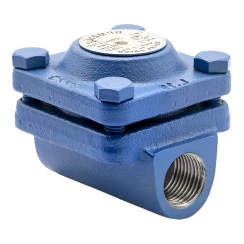
BPM21L Carbon Steel Balanced Pressure Thermostatic Steam Trap
Compact balanced pressure thermostatic steam trap with an integral strainer for industrial steam systems where installation space is limited.

Installation and maintenance instructions for BPM21L/BPM21LCV, covering safety information, installation, commissioning, operation, maintenance procedures and spare-parts ordering.
Select model
Safe operation of this product can only be guaranteed if it is properly installed, commissioned, used and maintained by qualified personnel in accordance with these Installation and Maintenance Instructions. General installation and safety instructions for pipeline and plant construction, as well as the proper use of tools and safety equipment, must also be followed.
Refer to these Installation and Maintenance Instructions, the product nameplate and the Technical Information Sheet to check that the product is suitable for the intended use or application.
This product complies with the requirements of the European Pressure Equipment Directive 2014/68/EU and falls within category SEP. It therefore does not carry the CE mark.
| Product | Group 2 gases | Group 2 liquids |
| BPM21L | SEP | SEP |
This product has been specifically designed for use on steam, air or water/condensate, which are Group 2 fluids under the above Pressure Equipment Directive. Use on other fluids may be possible, but Spirax Sarco should be contacted to confirm suitability for the application being considered.
Before installation, check material suitability, pressure and temperature, including their maximum and minimum values. If the product’s maximum operating limits are lower than those of the system in which it is being fitted, or if product malfunction could result in a dangerous overpressure or overtemperature event, ensure that a safety device is included in the system to prevent such over-limit conditions.
Also determine the correct installation position and direction of flow, and remove the protective covers from all connections before installation. Spirax Sarco products are not designed to withstand external stresses that may be induced by the connected system. The installer is responsible for considering these stresses and taking adequate precautions to minimise them.
Before working on the product, ensure safe access and, if necessary, provide a suitably guarded safe working platform. Arrange suitable lifting equipment if required.
Ensure adequate lighting, particularly where detailed or intricate work is required. Also consider what is currently in the pipeline, or what may previously have been in it, including flammable materials, substances hazardous to health and extremes of temperature.
Hazardous conditions around the product may include explosion-risk areas, lack of oxygen such as in tanks or pits, dangerous gases, extreme temperatures, hot surfaces, fire hazards such as during welding, excessive noise and moving machinery.
Consider the effect of the proposed work on the complete system. Could any action, such as closing isolation valves or electrical isolation, put any other part of the system or any personnel at risk?
Hazards may include isolating vents or protective devices, or making controls or alarms ineffective. Open and close isolation valves gradually to avoid system shocks.
Ensure that all pressure is isolated and safely vented to atmospheric pressure. Consider double isolation, or double block and bleed, and locking or labelling closed valves. Do not assume that the system has depressurised even when the pressure gauge indicates zero.
Allow time for temperature to normalise after isolation to avoid the risk of burns.
Before starting work, ensure that suitable tools and/or consumables are available. Use only genuine Spirax Sarco spare parts.
Consider whether you or others nearby need protective clothing to protect against hazards such as chemicals, high or low temperature, radiation, noise, falling objects, and risks to the eyes and face.
All work must be carried out or supervised by a suitably competent person. Installation and operating personnel should be trained in the correct use of the product according to these Installation and Maintenance Instructions. Where a formal permit-to-work system is in force, it must be complied with. Post warning notices if necessary.
Manual handling of large and/or heavy products may present a risk of injury. Assess the risks by considering the task, the individual, the load and the working environment, and use an appropriate handling method for the work being carried out.
In normal use, the external surface of the product may be very hot. At the maximum permitted operating conditions, the surface temperature of some products may exceed 300 °C (572 °F). Many products are not self-draining, so take particular care when dismantling or removing the product from an installation.
Products that are not self-draining must be protected against frost damage where they may be exposed to temperatures below freezing point.
The cover gasket contains a thin stainless steel support ring which may cause physical injury if it is not handled and disposed of carefully.
Unless otherwise stated in these Installation and Maintenance Instructions, this product is recyclable and no ecological hazard is anticipated when it is disposed of with due care.
Customers and stockists are reminded that, under EC health, safety and environmental law, when returning products to Spirax Sarco they must provide written information on any hazards and precautions to be taken due to contamination residues or mechanical damage that could present a health, safety or environmental risk.

Fig. 1 BPM21L
The BPM21L is a compact carbon steel balanced pressure steam trap with an integral strainer. It is ideally suited to applications where space is important, such as OEM equipment.
Capsule fill and operation: As standard, the fitted capsule operates at approximately 13 °C (55 °F) below steam saturation temperature (STD). Alternatively, a near-to-steam (NTS) capsule can be fitted to operate at approximately 6 °C (43 °F) below steam saturation temperature, or a sub-cooling (SUB) capsule can be fitted to operate at approximately 24 °C (75 °F) below steam saturation temperature.
Check valve: All versions can be supplied with an integral check valve and are designated BPM21LCV.
This product fully complies with the requirements of the European Pressure Equipment Directive 2014/68/EU.
The product is available with a manufacturer’s typical test report. All certification or inspection requirements must be stated when ordering. For further information, see Technical Information Sheet TI-P124-08.
3/8 in. and 1/2 in. screwed BSP T Rp (ISO 7-1) or NPT.
Socket-weld ends are available for 1/2 in. only.
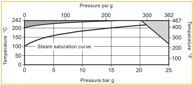
The product must not be used in the prohibited region shown.
The product should not be used in the indicated region or beyond its operating range, as damage to internal components may occur.
| Body design conditions | PN25 | ||
| PMA | Maximum allowable pressure | 25 bar g @ 120 °C | 362 psi g @ 248 °F |
| TMA | Maximum allowable temperature | 242 °C @ 20 bar g | 467 °F @ 290 psi g |
| Minimum allowable temperature | -10 °C | 14 °F | |
| PMO | Maximum operating pressure | 21 bar g @ 217 °C | 304 psi g @ 422 °F |
| TMO | Maximum operating temperature | 242 °C @ 20 bar g | 467 °F @ 290 psi g |
| Minimum operating temperature | 0 °C | 32 °F | |
| Maximum cold hydraulic test pressure | 38 bar g | 551 psi g | |
Before carrying out any installation, read Section 1, Safety Information.
Refer to these Installation and Maintenance Instructions, the product nameplate and the Technical Information Sheet to check that the product is suitable for the intended installation.
Note: If no drop leg is fitted, under low-load conditions steam may flow over the condensate in the bottom of the pipe and reach the trap. If the trap discharges to atmosphere, ensure that it discharges to a safe place, as the discharged fluid may be at 100 °C (212 °F).
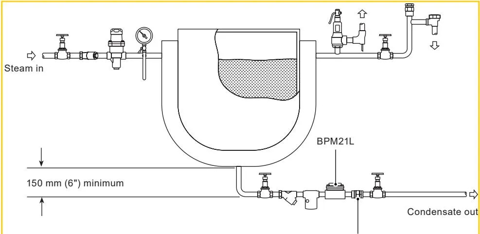
Fig. 2 Small process equipment arrangement, DVC41
After installation or maintenance, ensure that the system is fully functional. Carry out tests on any alarms or protective devices.
The operating element is a capsule containing a small quantity of special liquid with a boiling point below that of water. Under the cold conditions present at start-up, the capsule is relaxed. The valve is off its seat and fully open, allowing unrestricted removal of air. This is a feature of all balanced pressure traps and explains why they are well suited to air venting.
As condensate passes through the balanced pressure steam trap, heat is transferred to the liquid in the capsule. The fill liquid boils before steam reaches the trap. Vapour pressure inside the capsule causes it to expand and the trap closes. Heat loss from the trap then cools the water surrounding the capsule, the fill condenses and the capsule contracts, opening the valve and releasing condensate. When the temperature again approaches steam temperature, the cycle repeats.
Before carrying out any maintenance, read Section 1, Safety Information.
The cover gasket contains a thin stainless steel support ring which may cause physical injury if it is not handled and disposed of carefully.
Before undertaking any maintenance on the trap, isolate it from both the supply line and the return line and allow any pressure to safely normalise to atmosphere. The trap should then be allowed to cool. When reassembling, ensure that all joint faces are clean.
Maintenance can be completed with the trap in the pipeline once the safety procedures have been observed. It is recommended that new gaskets and spare parts are used whenever maintenance is undertaken. Ensure that the correct tools and necessary protective equipment are used at all times. When maintenance is complete, open isolation valves slowly and check for leaks.
Note: Care must be taken to ensure that the cover bolts (7) are progressively tightened to the recommended torque shown in Table 1.
Note: Care must be taken to ensure that the cover bolts (7) are progressively tightened to the recommended torque shown in Table 1.
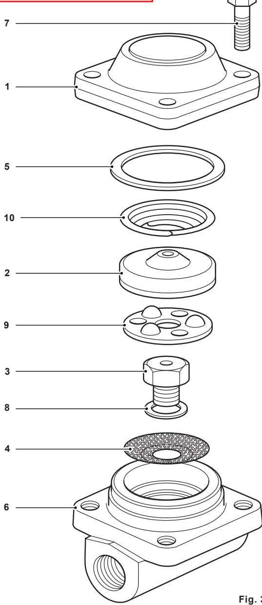
Fig. 3
Available spare parts are shown in solid outline. Parts drawn in broken outline are not supplied as spares.
| Capsule and seat assembly set | 2, 3, 5, 8, 9, 10 |
| Gasket set | 5, 8 |
| Strainer screen, pack of 3 | 4 |
Always order spare parts using the descriptions given under Available Spares, and state the size and type of trap.
Example: 1 off capsule and seat assembly set for a Spirax Sarco 1/2 in. BPM21L balanced pressure thermostatic steam trap with STD operation at 13 °C below steam saturation temperature.
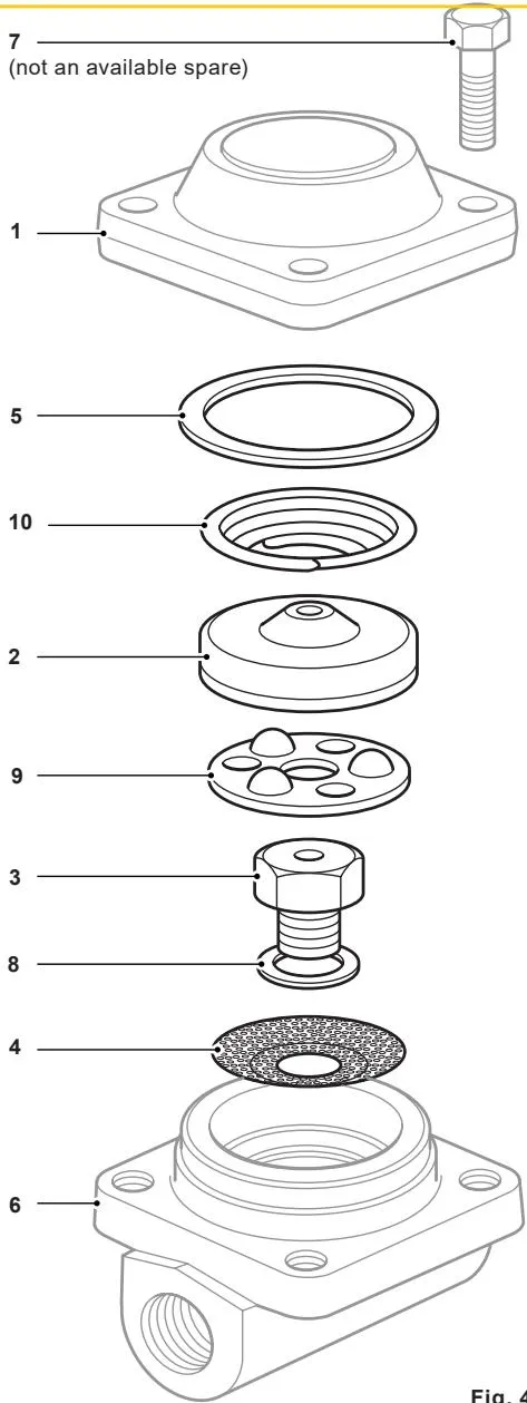
Fig. 4