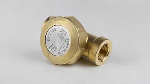
BPT13 Brass Pressure Balanced Thermostatic Steam Trap
Maintainable brass pressure balanced steam trap with angle, straight-through, integral strainer, and union inlet options.

Installation and maintenance instructions for BPT13A, BPT13AX, BPT13UA, BPT13UAX, BPT13S, BPT13SX, BPT13US, and BPT13USX brass pressure balanced thermostatic steam traps, covering safety, installation, commissioning, operation, maintenance, and spare parts, based on IM-P122-02.
Select model
BPT13A and BPT13AX 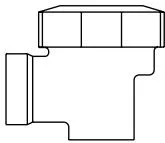
BPT13UA and BPT13UAX 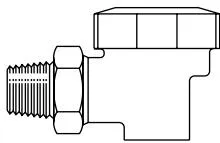
BPT13S and BPT13SX 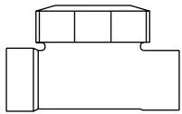
BPT13US and BPT13USX 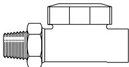
Safe operation of this product can only be guaranteed if it is properly installed, commissioned, and maintained by qualified personnel in accordance with the operating instructions (see section 1.11). Installation must comply with all relevant pipeline and building safety guidelines. Proper tools and necessary safety equipment must be used.
Refer to the installation and maintenance instructions, nameplate, and technical documentation to ensure the product is suitable for the intended application. This product complies with the requirements of the European Pressure Equipment Directive 97/23/EC and is classified as “SEP” (Sound Engineering Practice). Products within this classification do not require CE marking.
| Product | Group 2 Gas | Group 2 Liquid |
| BPT13A, BPT13AX, BPT13UA, BPT13UAX, BPT13S, BPT13SX, BPT13US, BPT13USX | SEP | SEP |
I) The product is designed for use with Group 2 fluids under the Pressure Equipment Directive, including steam, air, and water/condensate. Consult Spirax Sarco if the product is to be used with other fluids. II) Ensure the product materials are suitable for the operating conditions and that the maximum/minimum pressure and temperature of the system are within the product design limits. If the product maximum operating range is below the system conditions, or if product failure could lead to overpressure or overtemperature, install safety devices to prevent hazards. III) Ensure correct installation orientation and that the inlet and outlet connections are not reversed. IV) Spirax Sarco products cannot withstand external loads. Installers must prevent external forces from being applied to the product. V) Remove protective caps and nameplate protective film from all connections before installation into steam or other high-temperature systems.
Ensure sufficient space is available for safe operation and maintenance of the product after installation. If necessary, provide a safe working platform and lifting equipment before performing any work on the product.
Ensure adequate lighting, particularly for detailed or complex operations.
Consider the nature of the fluid in the pipeline and any fluids that may be present. Take precautions against flammable, health-hazardous, and extreme-temperature substances.
Be aware of explosion risks, oxygen deficiency (e.g., inside tanks, low-lying areas), hazardous gases, extreme temperatures, hot surfaces, fire hazards (e.g., during welding), excessive noise, and moving machinery.
Understand the complete system’s operating principle. Before any operation (such as closing isolation valves or operating electrical switches), consider whether it could endanger other parts of the system or other personnel.
Hazards include isolating vent lines or protective devices, or disabling controls or alarms. Open and close isolation valves slowly to prevent system shock.
Ensure the system pressure is isolated and fully vented. Consider using double block-and-bleed isolation, and lock or tag closed valves. Never assume a pressure gauge reading zero indicates a fully depressurized system.
Allow the product to cool to room temperature after isolation to prevent burns. If ‘O’ ring temperature reaches or exceeds 315°C (599°F), the ring will decompose, forming hydrogen fluoride gas (hydrofluoric acid). Avoid skin contact and inhalation of hydrofluoric acid fumes, which can cause skin burns and respiratory damage.
Ensure suitable tools and spare parts are available before starting work. Use only genuine Spirax Sarco spare parts.
Consider whether operators or nearby personnel require protective clothing against hazards such as chemicals, extreme temperatures, radiation, noise, falling objects, and eye or face injury.
All work must be carried out by or under the supervision of competent personnel. Installation and operating personnel must be trained in accordance with the product installation and maintenance instructions to ensure correct use of the product.
Where a permit-to-work system is in place, personnel must comply with it. If no such system exists, the responsible person must understand the nature of the work and assign safety assistants as necessary.
Warning notices must be posted where required.
Manual handling of large or heavy products carries a risk of injury. Lifting, pushing, pulling, carrying, or supporting loads by bodily force can cause injury, particularly to the back. Assess the task, individual capability, load, and working environment, and use appropriate handling methods for site conditions.
The external surfaces of the product may become very hot during normal operation. At maximum allowable operating temperature, surface temperature may reach 250°C (482°F).
This product does not self-drain. Take care when removing or moving the product from its installation position (refer to “Maintenance Instructions”).
For products that do not self-drain and are used in ambient temperatures below freezing, frost protection must be provided.
Except for ‘O’ rings, this product is recyclable and poses no ecological hazard if disposed of properly.
If the disposal process involves temperatures reaching 315°C, exercise care with the decomposition products of fluorocarbon ‘O’ rings (see section 1.8).
‘O’ rings:
In accordance with EC Health, Safety, and Environmental legislation, customers and retailers must provide hazard information when returning products. Exercise care with residual contaminants or mechanical damage that could cause health, safety, or environmental hazards. Hazard information must be submitted in writing, including health and safety data sheets, identifying any identified or potential hazards.
BPT13 is a maintainable pressure balanced thermostatic steam trap with a brass body.
Available models
| BPT13A | Angle connection |
| BPT13AX | Angle connection, integral strainer |
| BPT13S | Straight-through connection |
| BPT13SX | Straight-through connection, integral strainer |
| BPT13UA | Angle connection, union inlet |
| BPT13UAX | Angle connection, union inlet, integral strainer |
| BPT13US | Straight-through connection, union inlet |
| BPT13USX | Straight-through connection, union inlet, integral strainer |
Capsule - specify capsule model when ordering
Standard capsule - marked “STD”, discharges condensate at 12°C (53°F) below saturated steam temperature
Optional capsule - subcooled capsule “SUB” available, discharges condensate at 24°C (75°F) below saturated steam temperature.
“NTS” capsule available for critical applications, discharges condensate at 4°C (7°F) below saturated steam temperature.
The product fully complies with the European Pressure Equipment Directive 97/23/EC.
Manufacturer’s test reports are available. Note: If certification is required, specify at time of order.
Note: Refer to technical document TI-P122-01 for further product information.
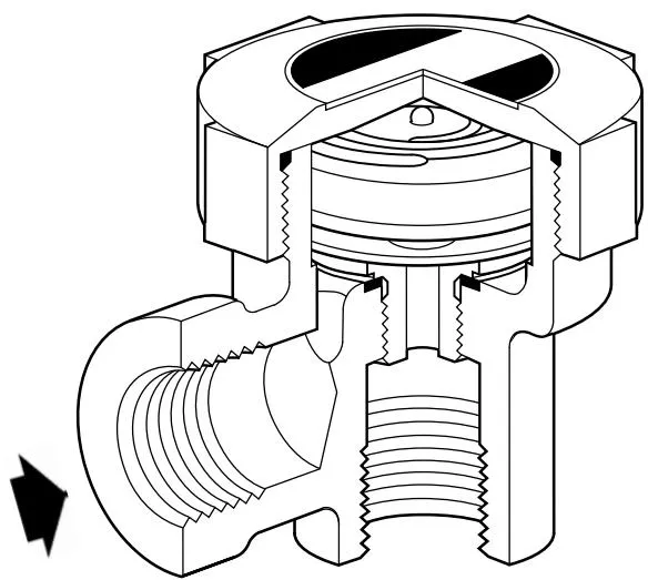
Fig.1 BPT13A
| Available sizes | Threaded connection standard |
| 3/8", 1/2", 3/4" | BSP (BS 21) or NPT |
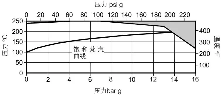
The product cannot be used in the shaded region.
| Body design conditions | PN16 | ||
| PMA | Maximum allowable pressure | 16 bar g @ 120°C | (232 psi g @ 248°F) |
| TMA | Maximum allowable temperature | 250°C @ 7 bar g | (482°F @ 102 psi g) |
| Minimum allowable temperature | -20°C | (-4°F) | |
| PMO | Maximum working pressure | 13 bar g @ 220°C | (189 psi g @ 428 psi g) |
| TMO | Maximum operating temperature | 250°C @ 7 bar g | (482°F @ 102 psi g) |
| Minimum operating temperature | 0°C | (32°F) | |
| Hydraulic test pressure (cold): | 24 bar g | (348 psi g) | |
Note: Before any installation work, read Section 1 “Safety Information”.
Refer to the installation and maintenance instructions, nameplate, and technical documentation to ensure the product is suitable for the intended application.
3.1 Check material, pressure, and temperature ratings. If the product maximum operating conditions are lower than the system it is installed in, ensure safety devices are fitted to prevent overpressure. 3.2 Check installation orientation and flow direction are correct. 3.3 Remove protective caps and nameplate film before installation into steam or other high-temperature systems. 3.4 BPT13 is designed for installation with the capsule in the horizontal plane and the cap at the top. For optimal performance, like most thermostatic steam traps, install a cooling leg / drain leg before the BPT13 to prevent condensate accumulation in the steam main. 3.5 When discharging to atmosphere, a silencer is strongly recommended at the trap outlet to reduce condensate velocity, noise, and erosion. 3.6 Isolation valves must be fitted to allow safe maintenance and trap replacement. 3.7 Open isolation valves slowly until normal operating conditions are reached. 3.8 Check for leaks and confirm correct operation. 3.9 Ensure sufficient clearance for cap removal. Minimum cap removal distance is 55 mm.
Note: If the trap discharges to atmosphere, ensure the discharge point is safe. Condensate temperature can reach 100°C (212°F).
After installation or maintenance, ensure the system can operate safely. Test alarms and protective devices.
The operating element is a capsule containing a special liquid with a boiling point below that of water. When cold, such as during startup, the capsule contracts, allowing the valve disc to lift off the seat and the trap to open fully, discharging air freely. This is a characteristic of all pressure balanced steam traps, making them suitable for use as air venting devices.
When condensate flows through the pressure balanced trap, heat is transferred to the liquid inside the capsule. Before steam reaches the trap, the filling liquid boils, the vapor pressure inside the capsule causes it to expand, and the valve closes. As the water around the capsule cools and dissipates heat, the filling liquid condenses, the capsule contracts, the valve opens, and condensate is discharged until steam arrives again. The cycle repeats.
Note: Before any maintenance work, read Section 1 “Safety Information”.
Before performing any maintenance on the trap, ensure both upstream and downstream pipelines are isolated and all pressure media are fully vented. Allow the trap to cool. Ensure all contact surfaces are clean before reassembly.
If safety procedures are followed, the trap can be serviced in-line. Use new gaskets and components during maintenance. Use correct tools and necessary protective measures throughout the procedure. After maintenance, slowly open the upstream and downstream isolation valves and check for leaks.
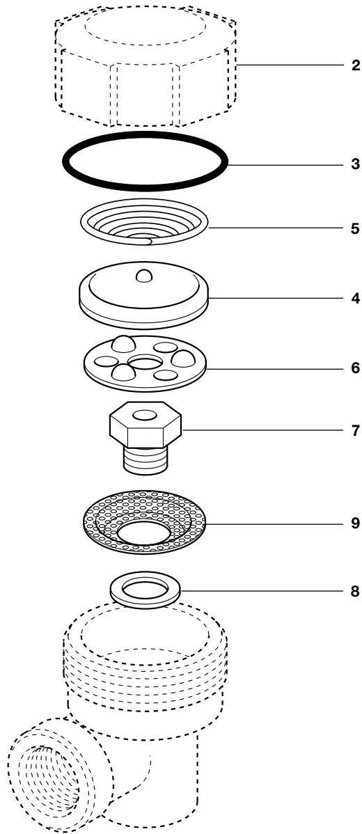
Fig.2 BPT13AX
Table 1 Recommended Tightening Torques
| Part No. | Part | Hexagon A/F | Torque N m | ||
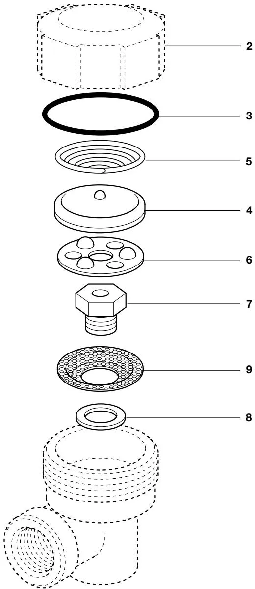
| 2 | Cap | 'O' ring | 50 mm | 50 - 60 | (37 - 44 lb ft) |
| Gasket | 50 mm | 90 - 110 | (66 - 81 lb ft) | ||
| 7 | Seat | 17 mm | 35 - 40 | (26 - 29 lb ft) | |
Solid outlines indicate available spare parts. Dashed outlines are not supplied as spares.
Available spare parts
| Capsule and seat assembly | 3,4,5,6,7,8 | ||
| Cap gasket | Early model | (3 pcs) | 3 |
| 'O' ring | Current model | (2 packs, 3 pcs each) | 3 |
| Strainer | (3 pcs) | 3,9 | |
Note: Early models use conventional gaskets for cap sealing. Current models use ‘O’ rings for cap sealing. Two types of ‘O’ rings are available; select the correct type based on the body design.
Order spare parts according to the “Available spare parts” table, specifying size, model, and capsule type.
Example: 1 - Spirax Sarco 1/2” BPT13S pressure balanced thermostatic steam trap capsule and seat assembly
Note: If a non-standard capsule is fitted, the nameplate on the cap will be marked “NTS” or “SUB”. “NTS” capsule discharges near saturated steam temperature, suitable for applications such as hospital sterilizers and wet steam ovens. “SUB” capsule is intended for applications such as vacuum recovery systems. For further capsule information, refer to section 2.1. Specify the capsule model when ordering; otherwise, a standard capsule will be supplied. Early models may have different markings, such as “G” or “F”. “G” is equivalent to “NTS”, “F” is equivalent to “SUB”.
Fig.3 BPT13AX