

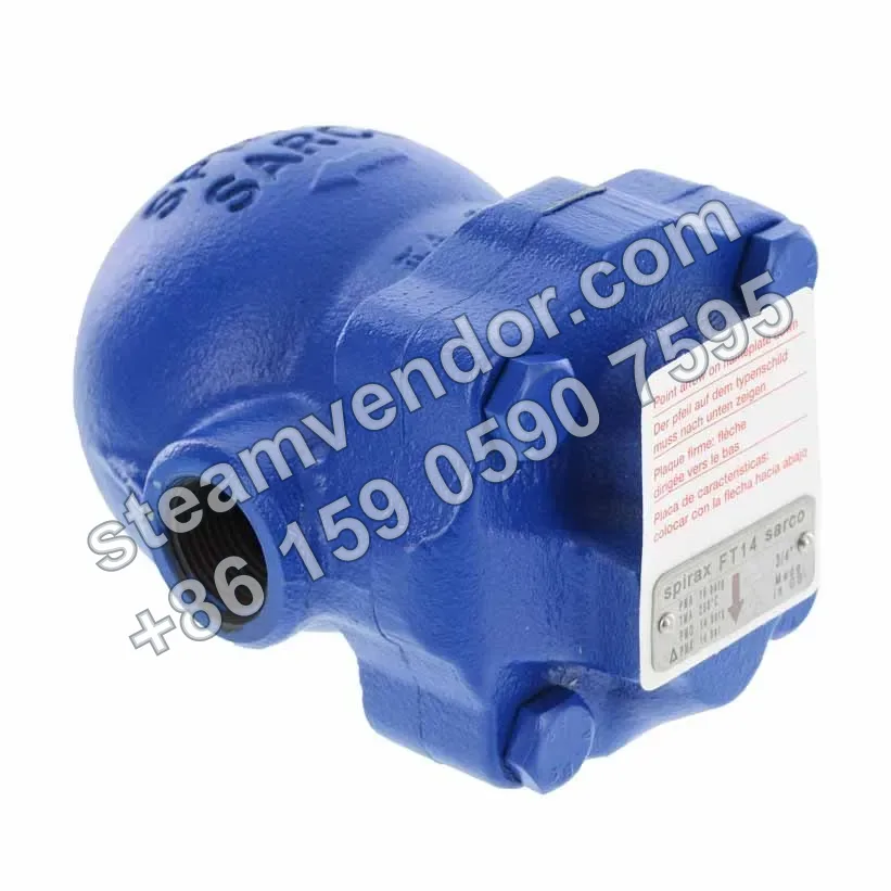
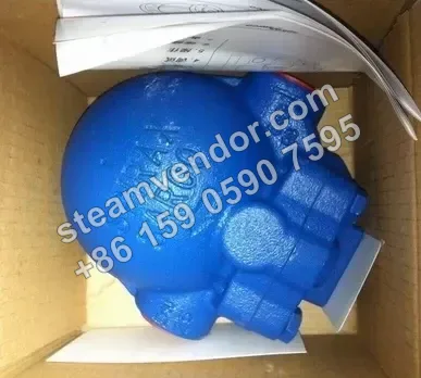
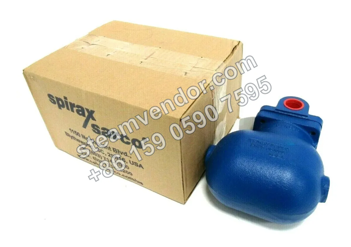
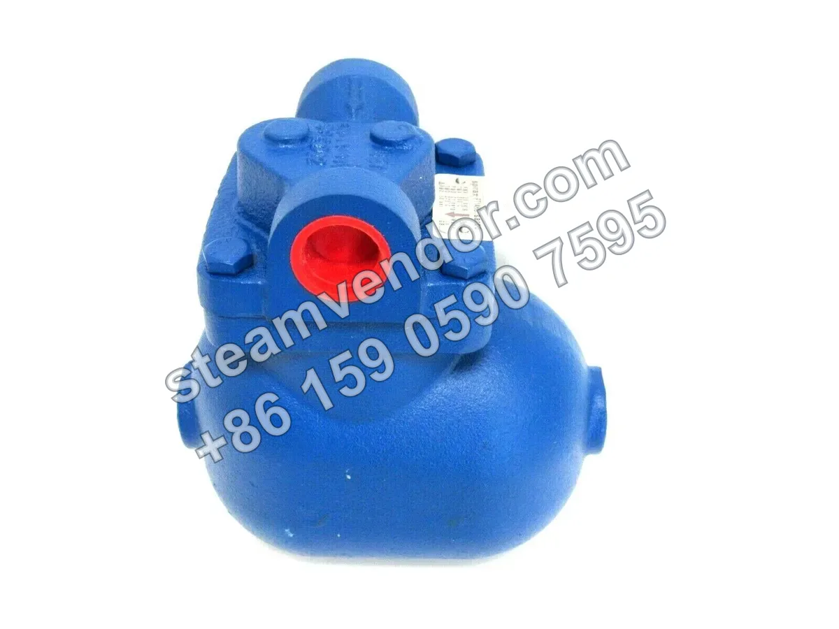
The Spirax Sarco FT14 series is a ductile iron ball float steam trap with threaded or flanged connections. Its body is rated PN16, with a maximum operating pressure of 14 bar g for saturated steam. The series features a stainless steel valve seat and float mechanism, and is fitted with a BP99/32 capsule, with a maximum operating temperature of 250°C. The FT14C model incorporates an air vent and a steam-lock release device (SLR), specifically designed to address condensate drainage from steam heat-transfer equipment at risk of steam locking.
FT14 Product Photo
1 / 4
Spirax Sarco FT14 Series Ductile Iron Ball Float Steam Traps
Ductile iron ball float steam traps for continuous condensate discharge from steam equipment, with an optional steam lock release device.
Select model
Genuine product assurance
We can help verify product data and purchasing details.
Model confirmation
Confirm model, connection and key options before ordering.
After-sales support
After-sales communication support is provided according to the order agreement.
Specifications
- Maximum allowable pressure
- 16 bar g@100°C
- Maximum operating pressure for saturated steam
- 14 bar g
- Maximum allowable temperature
- 250°C@13 bar g
- Maximum operating temperature
- 250°C@13 bar g
- Minimum operating temperature
- 0°C
- Minimum allowable temperature
- -10°C
- Maximum differential pressure
- 4.5 bar (FT14-4.5), 10 bar (FT14-10), 14 bar (FT14-14)
- Body design condition
- PN16
- Design maximum cold hydraulic test pressure
- 24 bar g
- Connection type
- Threaded or flanged connection
- Threaded connection sizes
- 1/2", 3/4", 1" (BSP or NPT)
- Flanged connection sizes
- DN15, DN20, DN25
- Flange standards
- EN 1092 PN16, ANSI 150, JIS/KS 20
- Body material
- Ductile iron DIN 1693 GGG 40
- Main valve seat material
- Stainless steel BS 970 431 S29
- Float lever mechanism material
- Stainless steel BS 1449 304 S16
- Capsule type
- BP99/32
- Superheat capability of capsule
- 150℃@0 bar g, 50℃@32 bar g
- Pressure equipment certification
- European Pressure Equipment Directive 97/23/EC
Application scenarios
Steam heat exchanger drainage with a risk of steam locking
For steam heat exchangers where the condensate discharge branch is at risk of steam locking, the FT14C configuration can be selected. This model includes an air vent and a steam lock release device (SLR) to address steam locking during condensate discharge.
Selection points
Multiple maximum differential pressure ratings to match operating conditions
The FT14 series is available with three maximum differential pressure ratings: 4.5 bar, 10 bar, and 14 bar. Select the appropriate rating according to the actual differential pressure.
Multiple flow-direction configurations
The FT14 series is available in standard horizontal, horizontal R-L, horizontal L-R, and downward vertical flow configurations. Select the appropriate version based on the site piping direction and available installation space.
BP99/32 liquid capsule for specified superheated steam conditions
The FT14 uses a BP99/32 liquid capsule and can be used for superheated steam service. The superheat limit is 150°C at 0 bar g and 50°C at 32 bar g.
Ductile iron body with stainless steel critical internal components
The body is made of DIN 1693 GGG 40 ductile iron. The main valve seat and float lever mechanism are made of stainless steel.
Threaded and flanged connection configurations
The product can be supplied with BSP or NPT threaded connections, or with flanged connections. Available flange standards include EN 1092 PN16, ANSI 150, and JIS/KS 20.
FT14C with air vent and steam-lock breaker
The FT14C is equipped with an air vent valve and steam-lock breaker, making it suitable for applications where steam-lock risk may occur.
Installation & maintenance notes
Install according to the specified flow direction and orientation
Install the product according to the specified flow direction and orientation for the particular FT14 model. Standard versions are installed horizontally and arranged in the R-L or L-R direction, while FT14(V) is installed vertically downward to ensure proper float mechanism operation and condensate drainage.
Check maximum differential pressure and pressure-temperature limits
Check the system operating conditions against the specific FT14-4.5, FT14-10, or FT14-14 model. The actual maximum differential pressure must not exceed 4.5 bar, 10 bar, or 14 bar respectively, and the operating pressure and temperature must remain within the product's specified limits.
FAQ
How does the FT14 float steam trap work?
The FT14 uses a float mechanism to control discharge automatically. An integral air vent assists with the automatic removal of air and condensate, ensuring automatic condensate discharge and stable system pressure in steam systems.
How should the different FT14 models be selected for different applications?
FT14(R-L) and FT14(L-R) are versions with different horizontal connection directions, while FT14(V) has a vertical connection with downward flow. FT14C adds a steam lock release device (SLR), and FT14X includes an integral strainer. The specific configuration should be selected according to the required size, connection direction, and whether air venting or filtration is required.
What sizes are available for the FT14, and how is it connected to the piping?
Threaded connections are available in ½, ¾, and 1 inch (BSP or NPT). Flanged connections are available in DN15, DN20, and DN25 (EN 1092 PN16, ANSI 150, and JIS/KS 20).
What are the key features of the valve's materials and structural components?
The body is made of ductile iron (DIN 1693 GGG 40), and the main valve seat is made of stainless steel. The cover and other critical components use appropriate steel and stainless steel materials. The assembly includes a float lever mechanism, air vent assembly, and SLR device to ensure reliability under high-temperature and high-pressure conditions.
What should be considered during installation and maintenance?
Follow the installation and maintenance instructions supplied with the product. Ensure that the flow direction matches the arrow on the body and that the float arm is horizontal to allow the float to move freely. The flow direction can be adjusted on site when required.
What connection types and size ranges does the FT14 support?
Threaded connections support 1/2", 3/4", and 1" (BSP or NPT). Flanged connections support DN15, DN20, and DN25, with flange standards of EN 1092 PN16, ANSI 150, and JIS/KS 20.