

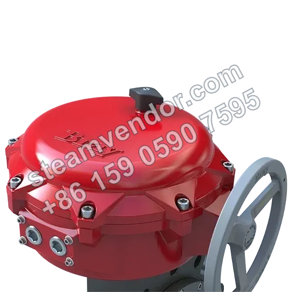
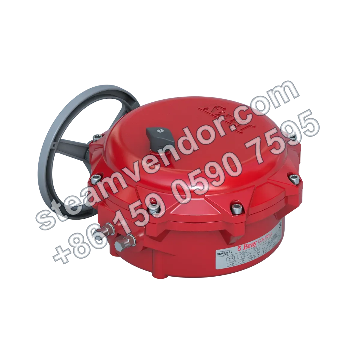
Bray 70-HAZ is a hazardous-location electric actuator for quarter-turn valves, featuring a 120 VAC single-phase reversible permanent split-capacitor motor and output torque from 800 to 2,000 in-lb (90-226 Nm). It is UL certified for designated Class I and II divisions and incorporates self-locking worm gear transmission and an ISO 5211 mounting interface for automated valve control in areas with flammable gases, vapors, or combustible dust.
70-HAZ Series hazardous-location electric actuator product image
1 / 3
Bray 70-HAZ Hazardous Location Electric Actuator
Electric control for hazardous-location quarter-turn valves, supporting 120 VAC input
Genuine product assurance
We can help verify product data and purchasing details.
Model confirmation
Confirm model, connection and key options before ordering.
After-sales support
After-sales communication support is provided according to the order agreement.
Specifications
- Output Torque
- 800 to 2,000 in-lb (90-226 Nm)
- Rated Voltage
- 120 VAC
- Control Options
- IRB
- Input Signal
- 120 VAC
- Motor Type
- Single-phase, reversible, permanent split capacitor motor
- Operating Temperature Range
- -20°F to 150°F (-29°C to 65°C)
- Hazardous Location Rating
- Class I, Divisions 1 and 2, Groups C and D; Class II, Divisions 1 and 2, Groups E, F, and G
- Certification
- Hazardous-location UL certified (120V only) (U.S. and Canadian standards)
- Mounting Standard
- ISO 5211
- Applicable Valve Type
- Quarter-turn valves
- Switch Configuration
- 2 standard, up to 5 SPDT
- Output Drive
- Self-locking worm and worm gear drive
- Travel Range
- 0° and 90°
- Manual Override
- Push-pull handwheel with automatic motor power cutoff during use
Application scenarios
Electric Control of Quarter-Turn Valves in Hazardous Areas with Flammable Gases or Vapors
For electric control of quarter-turn valves in Class I, Division 1 and 2, Groups C and D hazardous locations using a 120 VAC power supply. This series is UL certified for the applicable hazardous locations and uses a self-locking worm gear drive to maintain valve position.
Quarter-Turn Valve Automation in Hazardous Areas with Combustible Dust
For automated control of quarter-turn valves in Class II, Division 1 and 2, Groups E, F, and G hazardous locations. The actuator can be mounted via an ISO 5211 interface and is UL certified for the applicable hazardous locations.
Selection points
UL-Certified Configuration for Hazardous Locations
Suitable for Class I, Division 1 and 2, Groups C and D, and Class II, Division 1 and 2, Groups E, F and G hazardous locations, with UL certification to U.S. and Canadian standards for 120 VAC only.
Separated Control Center and Power Center Design
The control center and power center are separated. The power center in the base integrates the motor, gear train, capacitor, output drive, and heater, and is designed to require no customer servicing.
Self-Locking Worm Gear Position-Holding Drive
The output drive uses a self-locking worm and worm gear transmission to hold the valve in the required position without an additional electric or mechanical braking system.
Push-Pull Handwheel Power-Off Override
A push-pull handwheel is used for manual override. Motor power is automatically disconnected when the handwheel is engaged, with no additional tools or levers required.
External Adjustable Mechanical Travel Stops
Stainless steel mechanical travel stops are located outside the base and can be adjusted in the field without removing the cover to prevent overtravel during manual override.
Installation & maintenance notes
Hazardous Location Environment and Certification Compatibility
Before installation, verify that the site hazardous area classification complies with the product's specified hazardous location ratings and certification scope, including Class I, Division 1 and 2, Groups C and D, and Class II, Division 1 and 2, Groups E, F and G.
Valve Interface and Mounting Alignment
This actuator shall be installed on quarter-turn valves in accordance with ISO 5211. Verify that the valve interface, output drive connection, and 0° to 90° travel requirements are compatible.
120 VAC Power Supply Configuration Verification
During installation, verify that the site power supply matches the 120 VAC rated voltage and input signal configuration of this model and complies with the voltage requirements of its hazardous location certification.
Manual Override Reset
When using the push-pull handwheel for manual operation, motor power is disconnected by the automatic power-off switch. After manual operation is complete, push the handwheel back to the electric operation position to restore electric control.
FAQ
How do 70-HAZ Series electric actuators operate?
This series positions and holds valves in the required position through a self-locking worm gear drive. The base integrates separate components including the motor, gear drive, and heater, while the power center and control center are separated to provide a compact design and simplified maintenance.
What are the key considerations for using this actuator in hazardous locations?
The product is designed to meet hazardous-location rating requirements, with protective ratings and UL certification to support safe operation in hazardous environments and compatibility with quarter-turn valves. Specific configurations must be confirmed according to the actual model and application conditions.
How is manual override performed, and how does it affect valve positioning?
The manual override system enables manual valve positioning through a handwheel. Motor power is automatically disconnected during operation, and the handwheel can be pushed in or pulled out to switch modes and maintain positioning. Field-adjustable mechanical travel stops are also provided to prevent overtravel.
How do output torque and power requirements affect selection?
The output torque range is 800 to 2,000 in-lb (90-226 Nm), with a 120 VAC supply and a single-phase reversible capacitor motor. When selecting a model, ensure that its torque and control requirements match the application and are compatible with the existing electrical system.
What installation and maintenance features are simplified in this series?
The motor, gear drive, and heater are integrated within the base, reducing on-site maintenance requirements. The power center is located in the base, and the components are designed to require no customer servicing, reducing maintenance complexity and on-site workload.
Documents
Product Brochure - Actuators and ControlsProduct information · EnglishProduct Brochure - Valve Automation Center (VAC)Product information · EnglishQuick Start Guide - Series 70 Electric ActuatorsProduct information · EnglishRecommended Specifications - Series 70 Electric ActuatorsProduct information · English