

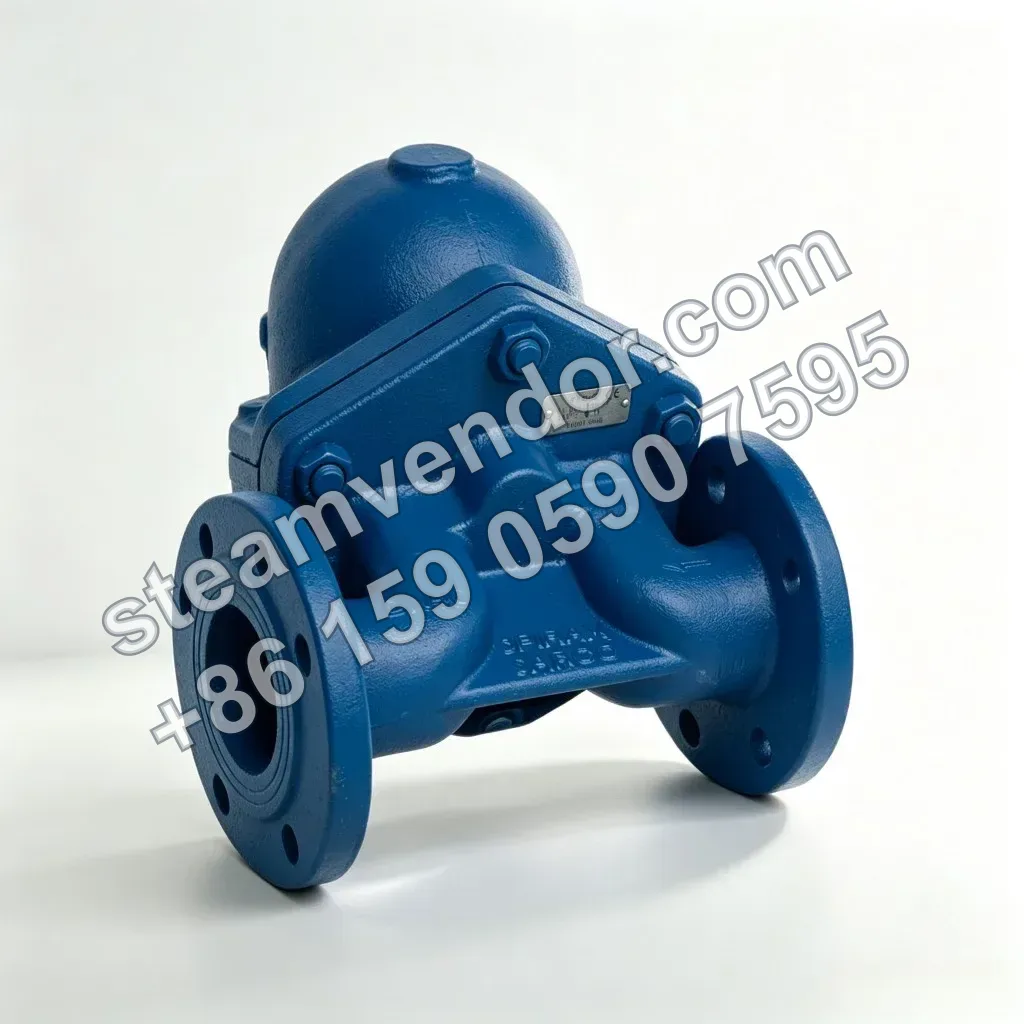
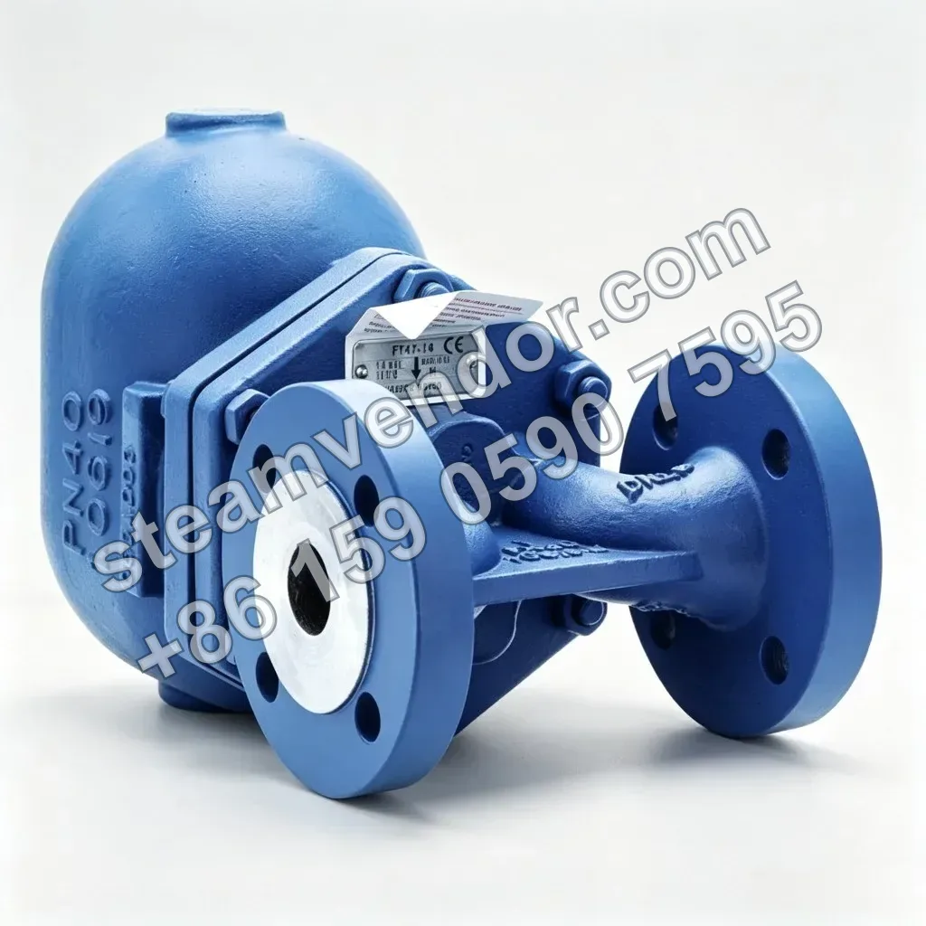
Spirax Sarco FT47 is a ductile iron flanged ball float steam trap, available in sizes DN15 to DN50 and with saturated steam operating pressure ratings up to 32 bar g. It features an integral automatic air vent. It is suitable for condensate drainage from automatically temperature-controlled steam heat transfer equipment and flanged steam equipment; for applications with a risk of steam locking, an FT47-C manually adjustable needle valve is available as an option for certain sizes.
FT47 product photo
1 / 2
Spirax Sarco FT47 Ductile Iron Flanged Ball Float Steam Trap
Ductile iron flanged ball float steam trap for condensate drainage from heat transfer equipment, with an optional steam lock release needle valve.
Genuine product assurance
We can help verify product data and purchasing details.
Model confirmation
Confirm model, connection and key options before ordering.
After-sales support
After-sales communication support is provided according to the order agreement.
Specifications
- Body material
- Ductile iron DIN 1693 GGG 40.3
- Connection type
- Flanged connection
- Flange standards
- EN 1092 PN40, PN25; ANSI B16.5 Class 150 (optional)
- Connection sizes
- DN15, DN20, DN25, DN40, DN50
- Installation orientation
- Horizontal or vertical installation
- Maximum allowable pressure
- 40 bar g @ 100°C
- Maximum allowable temperature
- 300°C @ 28 bar g
- Minimum allowable temperature
- -10°C
- Maximum operating pressure for saturated steam
- 32 bar g @ 239°C
- Maximum operating temperature
- 285°C @ 29 bar g
- Minimum operating temperature
- 0°C
- Maximum differential pressure
- 4.5 bar (FT47-4.5), 10 bar (FT47-10), 14 bar (FT47-14), 21 bar (FT47-21), 32 bar (FT47-32)
- Built-in automatic air vent
- Yes
- Steam-lock release device
- Optional FT47-C manual regulating needle valve
- Cover drain valve connection
- Optional 3/8" BSP or NPT threaded hole
- Certifications
- Pressure Equipment Directive 97/23/EC; EN 10204 3.1
Application scenarios
Condensate drainage from automatically temperature-controlled steam heat exchangers
Used for condensate drainage at the outlet of automatically temperature-controlled steam heat exchangers. The built-in automatic air vent can be used to release air during equipment start-up.
Condensate drainage from steam-heated equipment at risk of steam locking
Used for condensate drainage from steam-heated equipment at risk of steam locking. For horizontal installations with a maximum operating pressure not exceeding 21 bar g, the FT47 can be equipped with an optional FT47-C manual regulating needle valve to release the steam lock.
Installation in condensate branches of flanged steam equipment
Used in condensate branches of flanged steam equipment. Sizes from DN15 to DN50 are available, with the horizontal FT47 or the top-entry, downward-flow vertical FT47V selected according to the piping direction.
Selection points
Select by maximum differential pressure
FT47 is available in versions with maximum differential pressures of 4.5 bar, 10 bar, 14 bar, 21 bar, and 32 bar. Select the appropriate model according to the actual system differential pressure.
Ductile iron flanged valve body
The product features a DIN 1693 GGG 40.3 ductile iron valve body with a flanged connection. The valve body is designed for PN40.
Defined pressure-temperature operating limits
The maximum allowable pressure is 40 bar g @ 100°C, the maximum allowable temperature is 300°C @ 28 bar g, and the maximum operating pressure for saturated steam is 32 bar g @ 239°C. Verify the actual pressure-temperature combination during selection.
Horizontal or vertical installation versions
FT47 supports horizontal installation. FT47V is the vertical installation version, with flow from top to bottom. Select the installation version according to the site piping layout and verify the flow direction for the applicable size.
Built-in automatic air vent
FT47 has a built-in automatic air vent for steam-trapping applications where air must be removed from the system.
Optional steam-lock release device
FT47-C can be fitted with an optional manually adjustable needle valve as a steam-lock release device for applications with a risk of steam lock.
Installation & maintenance notes
Confirm flow direction according to size and installation orientation
For horizontal installation, DN15, DN20, and DN25 must be installed with flow from left to right when facing the valve body. DN40 and DN50 must be installed with flow from right to left. The vertical installation version FT47V must have downward flow.
Limit hydrostatic test pressure after installing internal components
When conducting a hydrostatic test after installing the internal components of the steam trap, the test pressure must not exceed 48 bar to prevent damage to the internal components.
Operate within the specified pressure and temperature ranges
Before installation and commissioning, verify the allowable operating pressure, maximum differential pressure, and temperature conditions for the specific model. Do not exceed the operating range specified for the product.
FAQ
How does the FT47 work, and how does it remove condensate from steam systems?
The FT47 separates steam and discharges condensate through the coordinated action of the float and main valve assembly inside the ductile iron body. The float automatically opens or closes the discharge path in response to changes in condensate level, integrating condensate drainage and air venting functions.
What is the installation difference between the FT47V and FT47, and how should horizontal or vertical installation be selected?
The FT47V is the vertical installation model, while the FT47 is the horizontal installation model. For horizontal installation, flow runs from left to right (DN15–DN25) or from right to left (DN40–DN50). For vertical installation, flow runs from top to bottom.
What key points regarding seat and chamber materials should be considered during selection?
The body and cover are made of ductile iron. The materials and configurations of internal components vary by size (DN15–DN25, DN40 and DN50). Selection should consider the operating temperature, pressure rating and installation orientation, with reference to the materials table and the accompanying installation guide.
Which flange connection standards are available, and can multiple flange interfaces be provided?
The flanged connection complies with EN1092 PN40/PN25, and the face-to-face dimensions comply with EN 26554 (Series 1). ANSI flanges are also available, with face-to-face dimensions likewise complying with EN 26554 (Series 1) and UNC-threaded bolt holes.
What points should be considered during on-site installation and maintenance to ensure correct operation?
Install the trap according to the flow direction marked on the body, and ensure that the float arm is horizontal so the float can move freely in the vertical direction. If a drain valve or steam-lock release device is required, follow the installation and maintenance guide IM-S02-30, and confirm the required certificates and test reports when placing the order.