

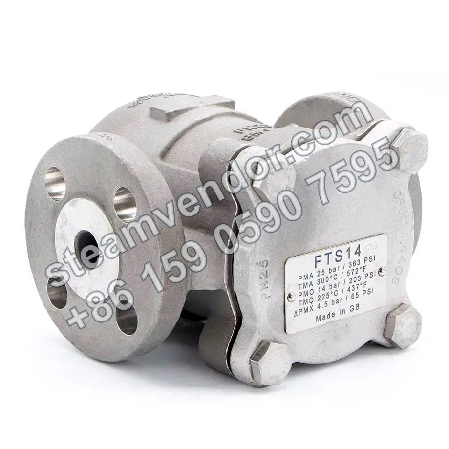
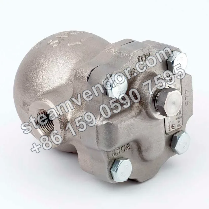
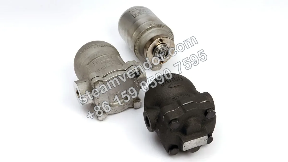
The Spirax Sarco FTS14 is a 316 austenitic stainless steel float steam trap with an integral automatic air vent, suitable for removing condensate and air during the start-up and operation of steam equipment. The valve body is rated PN25, with a maximum allowable temperature of 300°C. Threaded, socket weld, flanged, and hygienic clamp connections are available, along with an optional integral strainer. It can be used for condensate drainage from steam heat transfer equipment and clean steam-related equipment.
1 / 3
Spirax Sarco FTS14 316 Stainless Steel Float Steam Trap
316 stainless steel float steam trap for condensate drainage from heat transfer equipment, with an optional integral strainer.
Genuine product assurance
We can help verify product data and purchasing details.
Model confirmation
Confirm model, connection and key options before ordering.
After-sales support
After-sales communication support is provided according to the order agreement.
Specifications
- Product type
- Float steam trap
- Air venting function
- Built-in automatic air vent
- Valve body material
- Austenitic stainless steel 316, EN 10213-4(1.4408), ASTM A351 CF8M
- Sealing material
- Gray Viton, compliant with FDA CFR 21, P177, S2600
- Valve body design pressure
- PN25
- Maximum allowable pressure
- 25 bar g
- Maximum allowable temperature
- 300°C
- Operating temperature range
- -20°C to 225°C
- Maximum cold hydraulic test pressure
- 37.5 bar g
- Maximum differential pressure
- 4.5 bar, 10 bar, or 14 bar, configured according to the pressure range
- Connection types
- BSP or NPT threaded connection, socket weld, flanged connection, hygienic clamp connection
- Connection sizes
- 1/2 inch, 3/4 inch, 1 inch, DN15, DN20, DN25
- Thread standards
- BSP compliant with BS 21 and DIN 2999; NPT compliant with ANSI B 1.20.1
- Socket-weld standards
- ANSI B 16.11, BS 3799 Class 3000, DIN 3239
- Flange standards
- ANSI B 16.5 150Lb and 300Lb; EN 1092/PN16/25
- Installation
- Horizontal or vertical installation, with flow direction configurable from right to left, left to right, upward, or downward
- Optional filtration
- Built-in stainless steel strainer available as an option
- Optional temperature sensor connection
- The cover can be drilled and tapped with a 1/8 inch BSP threaded hole
- Certificates
- EN 10204 3.1 certificate available
Application scenarios
Condensate drainage from steam heat-exchange equipment
Used at the condensate outlet of steam heat-exchange equipment to remove condensate and air, maintaining effective heat transfer in process equipment. The valve can be adapted to different flow directions and installation arrangements by rotating the cover.
Air venting and condensate drainage during steam equipment startup and operation
Used to remove condensate and air during steam equipment startup and operation. The product features a built-in automatic air vent, which reduces the adverse impact of air on steam heat transfer and helps process equipment maintain operating efficiency.
Condensate drainage from clean-steam-related equipment
Suitable for condensate drainage and air removal in clean-steam-related equipment. The product features a 316 austenitic stainless steel valve body, sealing materials compliant with FDA CFR 21 requirements, and an optional hygienic clamp connection.
Selection points
316 Stainless Steel Valve Body
The valve body is made of 316 austenitic stainless steel, compliant with the EN 10213-4 (1.4408) and ASTM A351 CF8M material standards.
Multi-Directional Installation and Flow Configuration
Supports horizontal or vertical installation, with flow direction configurable as right-to-left, left-to-right, upward, or downward to suit different piping layouts.
Multiple Pipe Connection Options
Available with BSP or NPT threaded, socket-weld, flanged, and sanitary clamp connections, covering 1/2 inch, 3/4 inch, 1 inch, and DN15 to DN25 connection sizes.
Configuration by Maximum Differential Pressure
The maximum differential pressure can be configured for 4.5 bar, 10 bar, or 14 bar. Select the appropriate version according to the actual system differential pressure.
Built-In Automatic Air Vent and Optional Strainer
The product includes a built-in automatic air vent and can be configured with an integral stainless steel strainer.
Optional Temperature Sensor Port
The cover can be drilled and tapped with a 1/8 inch BSP threaded hole for a temperature sensor port.
Installation & maintenance notes
Install According to the Selected Installation Orientation and Flow Direction
FTS14 can be installed horizontally or vertically, with flow configured as right-to-left, left-to-right, upward, or downward. During installation, ensure that the on-site piping flow direction and installation orientation match the selected valve configuration.
FAQ
How does the FTS14 float steam trap work?
FTS14 uses a float structure made of austenitic stainless steel. Changes in the float position control condensate discharge and the opening of the air vent, enabling condensate drainage and air removal so that equipment can operate at maximum efficiency.
What connection types are supported by the FTS14 series, and how should they be selected?
Sizes include 1/2", 3/4", and 1", with BSP/NPT threaded, socket-weld, flanged, and hygienic clamp connections available. The specific connection type should be selected based on the site piping interface, pressure class, and hygiene requirements.
What are the pressure and temperature design limits of this valve?
The valve body is designed for PN25, with a maximum allowable temperature of 300°C, a maximum operating temperature of 225°C, a minimum operating temperature of -20°C, and a maximum cold hydraulic test pressure of 37.5 bar g. The specific operating temperature range must be confirmed based on the actual operating conditions.
Does FTS14 include a built-in air vent, and how do the options affect installation?
The standard model includes a built-in automatic air vent. Options include a built-in strainer, a manual adjustment needle valve for preventing steam locking, and a drilled cover for a temperature sensor. Installation must be confirmed and carried out according to the selected options and piping configuration.
How should the FTS14 size and connection type be determined for specific process conditions?
Select the appropriate size and connection type based on the system process pressure, fluid temperature, and piping interface standards. Refer to the illustrated dimensions and connection options table for comparison. The specific configuration must be confirmed according to the actual model and application conditions.