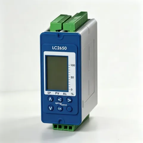
- Safety Information
- Product and Delivery Information
- System Overview
- Mechanical Installation 5. Electrical Installation
- Commissioning
- Quick Setup
- Full Setup
- Communication
- Maintenance 9. Fault Diagnosis
- Technical Information
Default Settings 11. Appendix
Modbus Protocol Overview
1. Safety Information
Compliance with the operating instructions and correct installation, commissioning, use, and maintenance by professionally qualified personnel is the sole guarantee of safe operation of this product (see Section 1.11).
Installation must comply with general installation and safety guidelines for piping and equipment, as well as correct use of tools and safety equipment.
In the United Kingdom, the IEE Wiring Regulations (BS 7671) must be followed; in other regions, the corresponding regulations must be followed.
All wiring materials and procedures must comply with the corresponding EN and IEC standards.
Warning
This product is designed and manufactured to withstand external forces during normal use. If this product is not used as a boiler controller or the installation process does not follow the instructions in this manual, during product modification or repair it may:
- Cause personal injury or death;
- Cause product/property damage;
- Invalidate the CE mark;
These guidelines should always be kept in a safe place near the boiler controller installation location.
Warning
This product complies with the Electromagnetic Compatibility Directive 2004/108/EC and meets all its requirements.
The product is suitable for industrial environments, and comprehensive and detailed EMC testing has been performed, with UK reference number BH LC 3250 2008.
Under the following conditions, this product may be exposed to interference exceeding heavy industry immunity limits:
- The product or its connecting cables are near wireless transmitters;
- The main power supply has interference. If the power supply may have interference, a line protector should be installed. The protector functions include filtering, rectification, surge and peak protection.
- Using mobile radios and mobile phones within approximately 1 meter of the product or its connecting cables may cause interference. However, the actual safe distance varies depending on the site environment.
The product complies with the Low Voltage Directive (2006/95/EC) and meets the following standards:
- EN61010-1:2001 Safety requirements for electrical equipment for measurement, control, and laboratory use;
The product, as a level controller type test, complies with the following standards:
- VdTÜV Water Level Control and Limiting Equipment 100 (07: 2006).
Electrostatic Discharge (ESD) Prevention
Care must be taken to prevent electrostatic discharge to avoid product damage.
For Steam Boiler Level Control and Level Limiting Products
The product must be selected, installed, operated, and tested according to the following:
Local or national standards and regulations
Guidance manuals (UK Health and Safety Directive PM5)
Requirements of the approving authority
Boiler inspection authority
Boiler manufacturer’s instructions
Steam boilers must be installed with two independent low water level limiting/alarm systems. Level sensors must be installed in separate protection tubes/chambers, with adequate space between the sensor end and the ground terminal.
Each sensor must be connected to an independent controller. During a low alarm, the alarm relay must cut off the boiler heating system.
The high water level alarm must be part of the water level control, or a separate system. If safety requirements are considered, a separate high water level alarm system must be installed.
In this case, during a high water level alarm, the relay must simultaneously cut off the boiler feedwater and heating system. All boiler water level limiting/alarms require periodic functional testing.
Level sensing probes and controllers are only part of the safety system. A complete system also requires other circuits (wiring, relays, alarm bells/lights).
Continuous safe and correct operation of water level control and limiting systems requires the use of appropriate water treatment. Please consult an authoritative water treatment company.
Symbols

The device uses double or reinforced insulation protection;

Functional ground terminal, ensures normal product operation; not used to guarantee electrical safety;
Safety ground

Safety ground
Caution, risk of electric shock;

Caution, danger, please refer to relevant documentation;
Opto-isolated current source signal;

Caution, the circuit board is susceptible to electrostatic discharge. Do not touch the circuit board without anti-static equipment.

AC, alternating current
1.1 Preparation for Use
i) Check that the product is suitable for the fluid being detected. ii) Check the suitability of materials, and the maximum and minimum values of pressure and temperature; if the maximum operating range of the product is lower than that of the system where it is to be installed, or if product failure may lead to dangerous over-temperature or over-pressure conditions, safety devices must be installed in the system to protect against such exceedances. iii) Determine the correct product installation location and fluid flow direction; iv) Spirax Sarco products cannot withstand additional stress; the installer should consider system stress and take appropriate preventive measures to reduce stress. v) Before installing the product in steam or high-temperature media, remove all connection port protection caps and the nameplate protective film.
1.2 Access
Before performing any operation, ensure safe access; if necessary, a safe working platform (with appropriate protection) is required. If necessary, arrange suitable lifting equipment.
1.3 Lighting
Ensure adequate lighting, especially where detailed or complex operations are performed.
1.4 Hazardous Liquids or Gases in Piping
Consider in advance the fluids that may exist or already exist in the piping; factors to consider include: flammability, health hazards, and temperature limits.
1.5 Hazardous Environment Around the Product
Consider: explosive environments, oxygen deficiency (e.g., in vessels or pits), hazardous gases, extreme temperatures, hot surfaces, fire hazards (during welding), excessive noise, and moving mechanical equipment.
1.6 System
Consider the impact of the planned operation on the entire system. Will the planned operation (e.g., closing shut-off valves, cutting power) cause danger to other parts of the system or any personnel?
Danger may arise from the shutdown of discharge or protection devices, or the cancellation of controls or alarms. Shut-off valves should be opened and closed slowly to avoid system oscillation.
1.7 Pressure Systems
Ensure that all pressure has been isolated and safely vented to atmospheric pressure. Consider double isolation and locking and tagging of closed valves. Even when the pressure gauge reads zero, the system cannot be considered pressure-free.
1.8 Temperature
After isolation, allow time for cooling to ambient temperature to avoid burns.
1.9 Tools and Spare Parts
Before starting use, ensure that suitable tools and consumable spare parts are available. Use only original spare parts provided by Spirax Sarco.
1.10 Protective Clothing
Consider whether you or nearby personnel need to wear protective clothing to prevent hazards such as: chemicals, high/low temperatures, radiation, noise, falling objects, and eye and face injuries.
1.11 Work Permit
All operations must be performed or supervised by suitable personnel qualified for the work. Installation and maintenance personnel must be trained on how to correctly operate this product according to the installation and maintenance guide.
Comply with formal “work permit” systems; operations must be strictly performed as described above. If no such system exists, it is recommended that the responsible person understand the operation being performed and, if necessary, arrange an assistant responsible for safety.
If necessary, post “caution” notices.
1.12 Manual Handling
Manual handling of large or heavy objects can cause danger or personal injury. Directly lifting, pulling, pushing, raising, or supporting loads by human force can cause personal injury, especially to the back. It is recommended that customers conduct a risk assessment considering the task, personnel, workload, and working environment, and adopt appropriate handling methods according to the working environment.
1.13 Residual Hazards
Under normal conditions, the outer surface of the product may be hot.
Many products do not have self-draining functions. Extreme care should be taken when disassembling products.
1.14 Freezing
When the product is exposed to sub-zero environments, valves without self-draining functions are at risk of freezing and must be protected.
1.15 Disposal
When disposing of this product, appropriate preventive measures should be taken according to local regulations.
Unless otherwise noted in the installation and maintenance guide, this product is recyclable and, if properly disposed of, has no harmful effect on the ecological environment.
1.16 Returns
Customers and stockists are reminded that, in accordance with EC Health, Safety and Environmental legislation, when returning products to Spirax Sarco, customers must provide information on hazards and the precautions taken when handling contaminated residues or mechanical damage that may pose risks to health, safety, or the environment. Safety data sheets for any hazardous or potentially hazardous substances must be provided in writing.
2. Product and Delivery Information
2.1 Introduction
The LC2650 is used for level control of conductive fluids. It has 2 independent alarm channels for high/low alarms.
Warning: The minimum conductivity when using LP20/PA20 is 5 μS/cm or 5 ppm at 25 °C.
The product can be panel, rail, or baseplate mounted, with 99-264 Vac power supply.
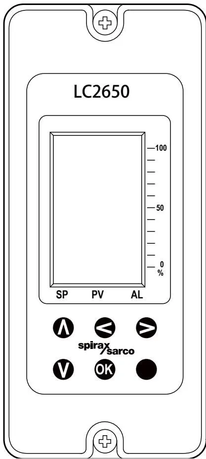
2.2 Front Panel
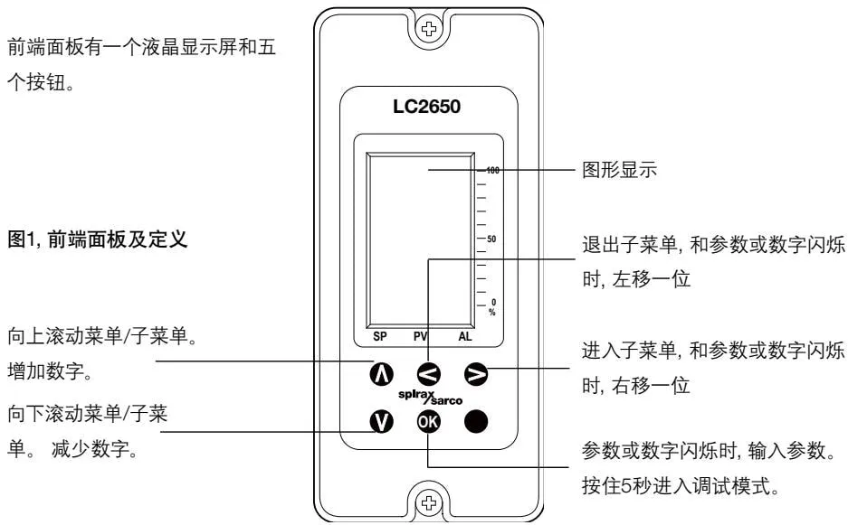
Figure 1 Front panel and definitions
2.3 Using the Buttons
A and V buttons:
- Scroll up and down the main menu and submenus
- Increase and decrease values in the main menu and submenus
◀ and ▶ buttons:
- Exit and enter submenus
- Move left or right in the main menu and submenus
OK button:
- Confirm input when values and parameters are flashing
- Enter commissioning mode (press and hold for 5 seconds)
Entering commissioning mode allows setting product parameters, allows the user to set and test outputs, and modify the password. See Section 6.
The parameter being edited is always displayed in the bottom right corner of the screen. Press OK to enter a new value. Press A and V buttons to scroll through values; the previously entered value will flash.
2.4 Run Mode
In run mode (normal), the display is divided into three areas:
- Four-digit large font value, displaying process variables and control parameters
- Information line, displaying control status and process units.
- Three bar graphs, displaying percentage of full scale (percentage of gauge glass) After initial power-up, run mode is automatically entered. The current value (PV) is displayed.
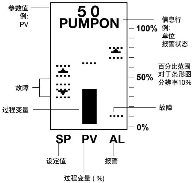
Figure 2 Graph definitions - bar graph mode
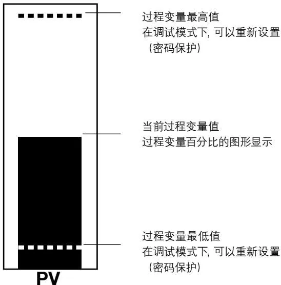
Figure 3 PV (conductivity) bar graph definitions
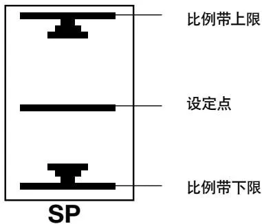
Figure 4 Setpoint bar graph definitions
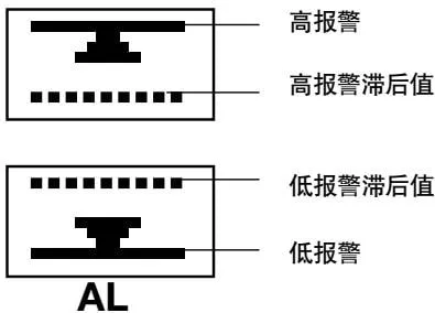
Figure 5 Alarm bar graph definitions
2.5 Information Line
The information line displays the level, alternately displaying alarm and pump or valve status information.
Fault status example:
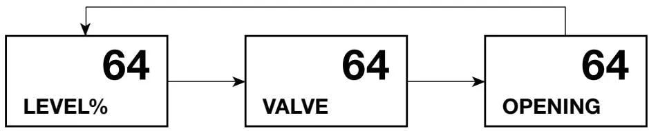
If an alarm occurs, pump or valve status is not displayed. ‘ALARM’ is displayed, followed by the alarm type. See Section 9 - Fault Diagnosis for fault types. Finally, the information line is divided into two parts.
Two alarm examples:
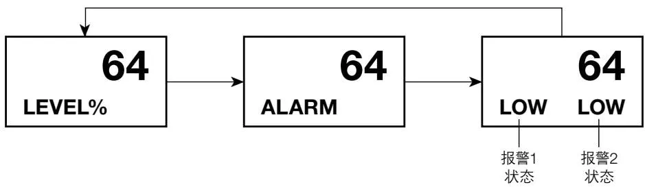
2.6 Parameter View Mode
In run mode, press the A button to view the currently selected parameter. Each parameter can be retained for 2 minutes until the button is pressed again. After initial power-up, run mode is automatically entered. The current level (percentage) is displayed. In run mode, general data is displayed in several screens, which can be switched via the up and down buttons. The default controller settings provided are as follows: - Password (7452)
LEVEL%
64
SP%
50
CTL BAND%
20
AL1 HIGH%
85
AL1 HYST%
5
AL1 DEL S
0
AL2 LOW%
20
AL2 HYST%
5
AL2 DEL S
0
OFFSET%
0
Process variable - displayed as percentage of gauge glass
Setpoint - as shown in commissioning mode. Normally 50% of gauge glass.
Set proportional band. Determines the upper and lower limits of valve operation. Set as percentage of gauge glass, with setpoint at 50%.
Alarm 1 can be set as high or low alarm, set as percentage of gauge glass.
Displays the hysteresis (damping) value of alarm 1, set as percentage of gauge glass.
Displays the delay of alarm 1 (for fluctuating boilers to increase damping effect), in seconds.
Alarm 2 can be set as high or low alarm, set as percentage of gauge glass.
Displays the hysteresis (damping) value of alarm 2, set as percentage of gauge glass.
Displays the delay of alarm 2 (for fluctuating boilers to increase damping effect), in seconds, default setting 0 seconds.
Only displayed when a steam flow meter is selected (two-element control). Displays the % offset value, set as percentage of gauge glass.
If no button is pressed for more than 5 minutes, it will return to displaying the current level value.
Two-element control - two-level setpoint
If STEAM OFFSET percentage is selected in the input menu, the two-level setpoint is displayed.
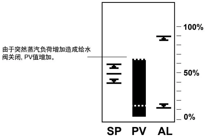
Figure 6 Graph display - setpoint rises to 65% - no steam flow compensation.
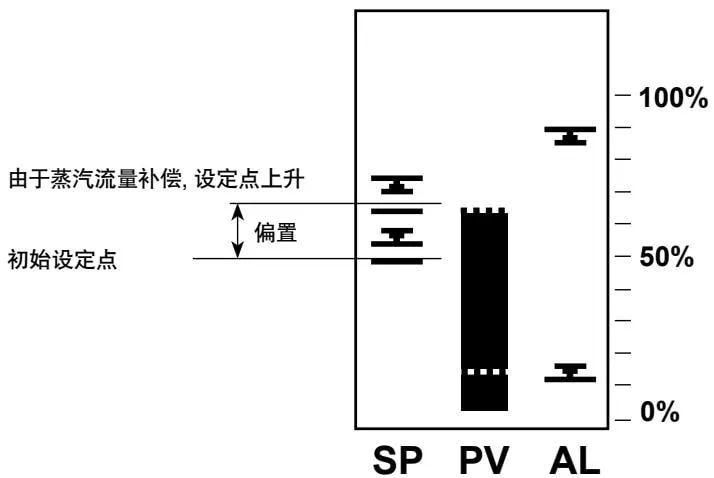
Figure 7 Graph display - with steam flow compensation
The second screen is overlaid on the SP graph, showing the offset of the steam flow meter on the setpoint. If there is no steam flow meter, the setpoint and proportional band are displayed singly.
At 100% steam load, the overlay display graph will move to the maximum percentage of the menu, and the initial setpoint remains visible, indicating offset 2.
2.7 Trend Graph
In run mode, press the ◀ button to display the trend graph.
Use ◀ and ▶ buttons to switch between run mode and trend graph.
It displays a record of level fluctuations over a set period of time, with the most recent events/values on the left side of the graph.
Time units can be minutes, hours, and days, up to 8 units. Main basic settings are made via the TREND menu.
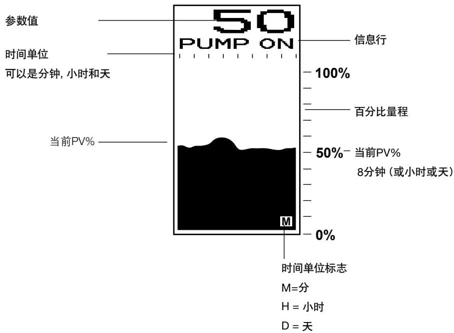
Figure 8 Graph display definitions - trend graph
2.8 Alarm/Error Display Information
In run mode, alarm/fault information is displayed on one screen. In run mode, scroll the menu to the alarm display screen. Press and hold the OK button for 3 seconds to clear the error message and re-energize the relay. If the cause of the error is not corrected, the same error will reappear. For latched errors and alarms, only the message disappears; the alarm relay remains de-energized until the correct password is entered in commissioning mode. If more than one error or fault exists, the next will be displayed after the previous one is cleared. See Section 9 - Fault Diagnosis.
2.9 Equipment Delivery, Transport, and Storage
Factory Shipment
Before shipment from the factory, the product has been tested, calibrated, and inspected to ensure normal operation.
Receipt
Upon delivery, each carton should be inspected to avoid external damage. Any visible damage should be immediately recorded on the delivery note.
Carefully open the carton and inspect the product for damage. If there is damage or loss, immediately notify Spirax Sarco and provide details. Additionally, notify the transport personnel of the damage and ask them to inspect the damaged product and packaging carton on site.
Storage
If storage is required before installation, ambient temperature 0-65 °C, 10%-90% relative humidity (non-condensing)
Before installation and power connection, ensure there is no condensation inside the product.
3. System Overview
3.1 Function
The LC2650 compares the input signal with the setpoint and controls the water level of boilers, tanks/vessels by operating pumps, valves, or solenoid valves.
On/Off Operation
Pump on-off control
2 alarm outputs
4-20 mA level output
Note: It may not be a pump, but a solenoid valve.
Regulation Control
The regulating valve control method is valve motor drive or 4-20 mA control signal.
2 alarm outputs
4-20 mA level output
Two- or Three-Element Regulation Control
The regulating valve control method is valve motor drive or 4-20 mA control signal.
2 alarm outputs
4-20 mA level output
Steam flow meter signal feedback
Feedwater flow signal feedforward
3.2 Input Signals
The product receives the following three signals:
- Level sensor or transmitter 1-6 V or 4-20 mA output
Note: The sensor must be long enough to cover the entire measurement range.
Steam flow meter 4-20 mA, used to compensate for steam load demand during rising steam load.
Water flow signal to compensate for feedwater flow fluctuations (three-element control)
3.3 Output Signals
Output signals can be connected to pumps or regulating control valves. Relays are provided for high and low alarms and one isolated 0-20 mA or 4-20 mA retransmission output signal.
Parameters can be transmitted via RS485/MODBUS communication.
3.4 Other Functions
On fluctuating boilers, additional delays can be selected to increase damping.
A test function provides diagnostic capabilities, allowing testing of inputs and setting of outputs on the front panel.
All commissioning parameters are password-protected to prevent unintended changes.
Can communicate with adjacent controllers via infrared (only with Spirax Sarco products). See Section 7 - Communication.
3.5 Typical Applications
Two-Element Control
A sudden increase in steam load causes a drop in boiler pressure, and steam bubbles in the water expand. This causes the water level to rise and the feedwater valve to close. Although the measured water level rises, the water in the boiler is decreasing and the feedwater valve needs to be opened. The two-element control system (sensor/controller or steam flow meter) increases the setpoint based on the steam flow meter output, changing the control action and preventing valve closure. For effective control, an accurate estimate of the water level at maximum steam flow (maximum load) is required. Water level rise differs under different operating conditions, such as steady full-load operation, intermittent, sudden load, and boiler pressure and boiler water TDS levels. Under different combustion conditions and steam loads, there will be differences between the boiler and the water level gauge.
Figure 9 Two-element control - electric valve 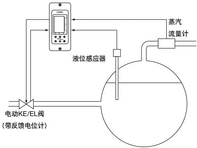
Figure 10 Two-element control - pneumatic valve 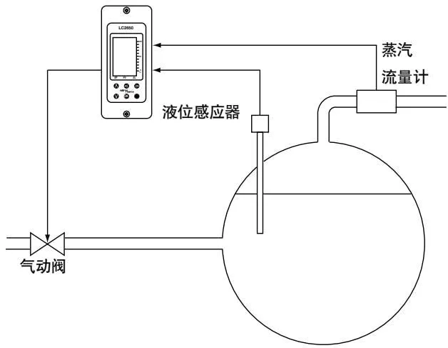
Three-Element Control
Under certain conditions, if feedwater pressure varies significantly, possibly affected by other boiler feedwater, three-element control is required. The water flow signal compensates for changes in feedwater pressure.
Figure 11 Three-element control 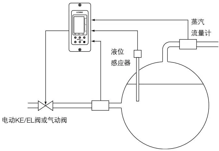
4. Mechanical Installation
Note: Before installing this product, please read the safety information in Section 1.
The product must be installed in a suitable industrial control panel or fireproof enclosure, providing impact and environmental protection. Minimum IP54 (EN60529) or Type 3, 3S, 4, 4X, 6P, and 13 (UL50/NEMA250) is required. Spirax Sarco can provide suitable plastic or metal enclosures.
The product meets UL508 Clause 23.2 and can be considered a 5 VA industrial fireproof button - part.
4.1 Environmental Conditions
The product installation environment should reduce the effects of heat, vibration, and electrical interference (see Section 1 - ‘Safety Information’).
Do not install the product outdoors without additional weather protection.
Do not attempt to open the product - the product is sealed, with no replaceable parts or switches.
4.2 Installation on DIN Rail
Clips and a set of self-locking screws are provided with the product for installation on a 35 mm DIN rail. On the rear of the housing, there are two sets of holes to determine the height position. The clip head can be adjusted to change position. Install the clip head in one set of holes and secure with the two provided screws. Ensure the clip and rail are clamped.
Note: Use only the screws provided with the product
4.3 Installation on Baseplate
On the baseplate, drill holes as shown in Figure 12.
Install the product on the baseplate, securing with two screws, nuts, and washers through the upper and lower slots.
Note: Do not drill holes in the product housing or use self-locking screws.
4.4 Installation on Cut Panel
(If using an instrument frame, minimum panel thickness is 1 mm)
The product has integral threaded sockets (M4 x 0.7) at the top and bottom
Two M4 x 25 mm screws, washers, and instrument frames are provided

Note: Do not use screws longer than 25 mm to avoid electric shock.
Cut the panel according to the dimensions in Figure 15, and drill screw holes as indicated.
After removing the backing from the washers, place them on the front of the product.
Frames can be used to improve appearance. If required, install them on the outside of the panel.
Install the product from the rear of the panel, securing with screws, washers (and instrument frames).
Tighten M4 screws to 1.0 - 1.2 Nm
Note: Do not drill holes in the product or use self-locking screws
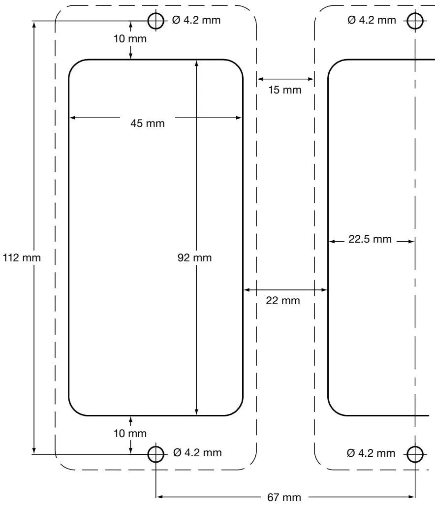
Figure 12 Baseplate/panel - cutout drawing
Fixing Plate Cutout Notes:
- Solid lines indicate the cutout required for the installation panel.
- Dashed lines indicate the product outline
- The minimum clearance required between products is 15 mm for heat dissipation and cooling.
- For panel and wall mounting, the mounting hole dimensions are the same.
5. Electrical Installation
Note: Before installing this product, please read the safety information in Section 1.

Warning: Before touching the wiring terminals, disconnect the power supply as there may be contact with hazardous voltage.
Use only the connectors provided with the product, or spare parts. Using other different connectors must comply with product safety and authorization.
5.1 General Wiring Instructions
The product has been designed with user safety in mind, but the following points must be noted:
- Maintenance personnel must be qualified to operate under hazardous voltage.
- Ensure correct installation. Failure to follow these rules may reduce the safety level of the product.
- The product design relies on building installation overcurrent protection and main isolation.
- All phase conductors must be fitted with 3-amp current-limiting protection devices. If current-limiting protection devices are installed on both power lines, the operation of one device must trigger the other. Please refer to IEC60364 (Building electrical installations), or follow local regulations for overcurrent protection requirements.
- Relay circuits must be fitted with 3 A fast-blow fuses.
- Relay contacts must use the same phase as the main power supply.
- Designed according to installation category II.
- Wiring standards:
IEC60364 - Low-voltage electrical installations
EN50156 - Electrical equipment for furnaces and ancillary equipment
BS6739 - Instruments for process control: installation design, practice, or corresponding local standards.
National and local electrical codes (NEC) or Canadian Electrical Code (CEC) for the United States and Canada Note: Use NEC Class 1, with temperature rating greater than 75 °C. If cables are exposed to higher temperatures, select a higher temperature rating.
- The shield of signal cables must be connected to ensure electromagnetic compatibility.
- All external circuits must meet and maintain IEC 60364 or equivalent double protection requirements.
- Additional measures must be taken to prevent accessible components (such as signal terminals) from coming into contact with power lines if power terminals suddenly become loose. Additional devices should be as close to the circuit board as possible, but no additional force should act on the wiring terminals. For example, use cable ties to bundle live and neutral wires together. If one becomes loose, the other will prevent it from contacting other components.
- A disconnecting device (switch or circuit breaker) must be provided in the building system, and this product must:
- Have sufficient breaking capacity;
- Be as close to the equipment as possible for easy operator access;
- Not be installed in a difficult-to-operate location;
- Be able to disconnect all phase conductor terminals;
- Be labeled as the product’s disconnecting device;
- Not affect protective grounding;
- Not be used as the main power supply;
- Comply with IEC60947-1 and IEC60947-3 disconnecting device requirements;
- See Section 10 ‘Technical Information’ for terminal and cable specifications
5.2 Main Wiring
- Please read Section 5.1 - General Wiring Instructions before connecting the main power supply.
- The terminal plug has wiring markings.
- All live conductor terminals must be fitted with fuses; 4 Double or reinforced isolation must be used between the following devices:
Live conductor terminals (main power and relay outputs)
Other low-voltage devices (other components/terminals/wires)
- The relays and switching devices shown on the wiring diagram are in the de-energized position.
Disconnecting devices comply with IEC 60947-1 and IEC60947-3 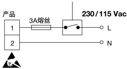
Figure 13
Disconnecting devices comply with IEC 60947-1 and IEC60947-3 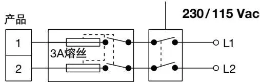
 Figure 14
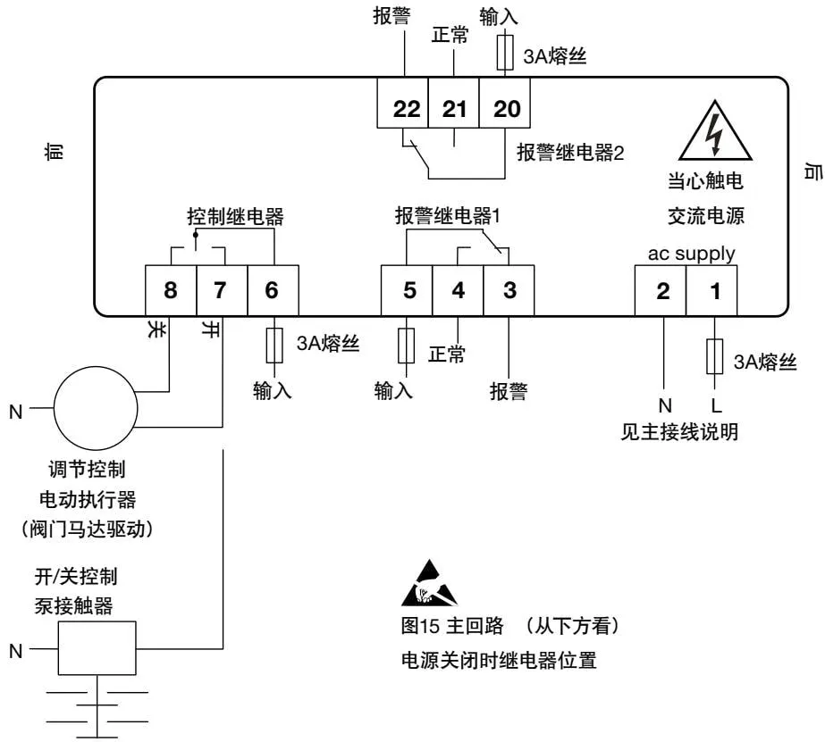
Figure 15 Main circuit (viewed from below) relay position when power is off
5.3 Signal Wiring Instructions
If signal cables or shields are grounded at both ends, loop currents will be generated due to unequal ground potentials (voltages) at both ends. If the wiring diagram is correctly followed, the sensor should be grounded at one end.
Product grounding is functional grounding, not protective grounding.
Protective grounding prevents electric shock in the event of a single fault. Functional grounding ensures normal operation of the product. In this product’s application, functional grounding serves as a source or discharge pool for electromagnetic interference. The ground terminal must follow EMC directive grounding.
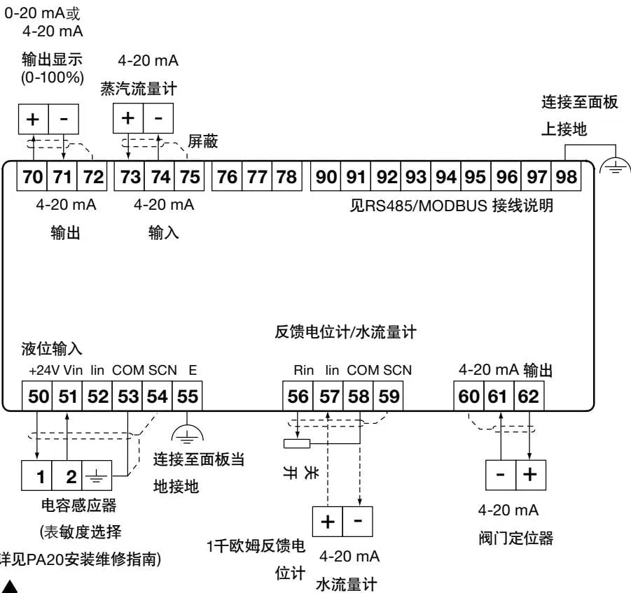
E = functional ground, connected to panel local ground.
Figure 16 Signal circuit (top view)
5.4 Sensor Wiring
The maximum cable length for all transmitters is 100 meters.
Note:
It is important to determine the sensitivity of the PA20 preamplifier (see PA20 installation and maintenance guide for details).
5.5 Level Sensors
The output signals from PA20 and LP20 capacitive level sensors can be connected to multiple flow meters (see example below).
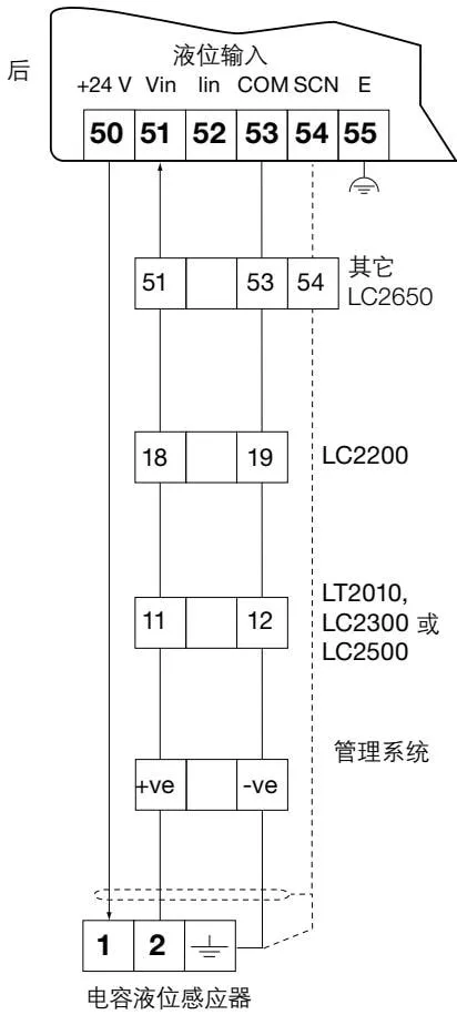
 Figure 17 Multiple controllers connected to one PA20
Each instrument needs to be able to accept 1-6 Vdc signals, and only one instrument needs to provide 24 V power. In this example, the LC2650 provides power to the PA20.
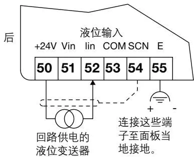
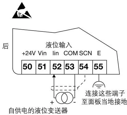
 Figure 18 4-20 mA level transmitter
5.6 UL Specification PA20 Wiring Diagram
PA20 preamplifier and LP20 capacitive sensor (see PA20 and LP20 installation and maintenance guides for details)
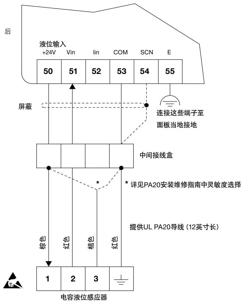
Figure 19
5.7 EIA/TIA-485 Communication Wiring
The controller can be connected as a slave to a 2-wire or 4-wire EIA/TIA 485 network
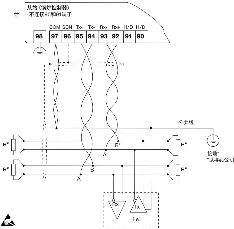
Figure 20 RS485/Modbus full-duplex circuit (top view)
EIA/TIA-485 communication wiring instructions:
Use symbols (A=Tx-, B=Tx+ and A’=Rx-, B’=Rx+)
The signal direction is relative to the controller as a Modbus slave, that is, Tx+ from the product (slave) connects to Rx+ of the master.
If the distance is less than 1.5 meters, twisted pair is not required, standard shielded cable is sufficient.
H/D (half-duplex) terminals are used to select 2-wire or 4-wire Modbus:
1 For 2-wire, connect terminals 90 and 91
2 For 4-wire, do not connect terminals 90 and 91
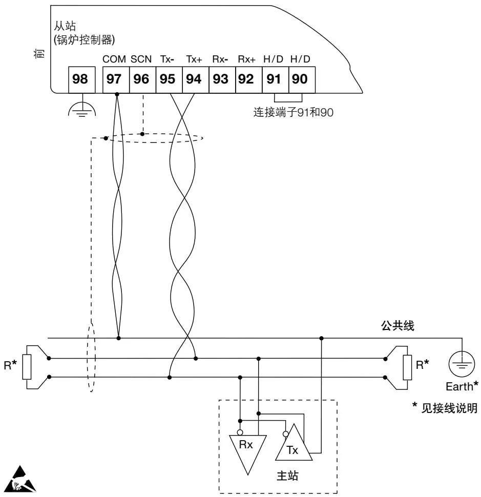
Figure 21 RS485/Modbus half-duplex circuit (top view)
EIA/TIA-485 Wiring Instructions (continued):
The bus common line must be directly grounded at one ground point. Generally this point is near the master.
To match the wire resistance on the bus, terminal resistors are usually installed on both sides of the bus. Typically use a 150 Ω (0.5 W) or 120 Ω (0.25 W) resistor in series with a 1 nF (10 V) capacitor, but the ideal method is to match the bus resistance with the resistance of each device.
When communication distance < 300 m at 9600 Baud, terminal resistors may not be used;
- See Section 10, “Technical Information” for cable specifications
6. Commissioning
6.1 Overview
All commissioning is performed on the product’s front panel.
Warning: When entering commissioning mode, the product will stop some control functions. The control relay closes the valve or stops the pump. For safety reasons, the alarm relay continues to function. To restore normal control function, return to the run menu.
Warning: If no button is pressed for more than 5 minutes, it will return to run mode and display an error. If commissioning is incomplete, control function will not operate.
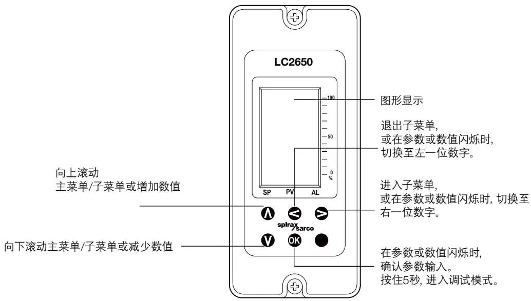
Figure 22 Display panel and buttons
6.2 Entering Commissioning
In run mode, press and hold the OK button for 5 seconds to enter commissioning mode.
The bar graphs disappear, displaying ‘PASS CODE’ and ‘8888’ in the bottom right corner of the screen. The flashing number indicates the cursor position. The default factory password is 7452, but it can be modified in commissioning mode. Use A and V to increase or decrease the flashing value, and B and C to move the cursor to set the password.
Press and hold OK to confirm the entered password. If an incorrect password is entered, the display automatically returns to run mode.
PASS CODE
8888
6.2.1 Commissioning Mode Wizard
After correctly entering the password, the following will be displayed:
At any step, to exit commissioning mode, press and hold ◀ to return to run mode.
Use A and V to scroll the first-level menu.
Press ▶ to enter the next-level submenu. The first-level menu remains displayed at the top of the screen, and the submenu is displayed on the next line. Continuing to enter the next-level menu, the list becomes longer, displaying the menu structure.
MODE
6.2.2 Changing Setting Parameters
If a submenu requires parameter modification, the corresponding unit (if any) will appear on the next line (in parentheses) and the parameter itself will appear in the bottom right corner. The first digit will start flashing, at which point the parameter can be modified.
If the OK button is pressed, the displayed value will be saved. If the button is pressed and the parameter has not changed, the submenu title, parameter, and unit will disappear, returning to the previous menu.
Note: If a value outside the parameter range is selected, an exclamation mark appears to the left of the symbol.
6.3 Quick Setup - Introduction
This section allows the user to perform the minimum settings to operate the system.
Accept factory default settings; when the original defaults have not been changed, the system can operate. Refer to the default settings in Section 10 for confirmation.
If required, settings can be made according to individual customer/application needs.
Warning: - It is important that you comply with national/local regulations and guidance instructions, and the boiler manufacturer’s recommendations. The set parameters will enable safe boiler operation.
Calibrate Water Level
Lower the water level to the lowest point (in boiler applications, the water level must be visible in the gauge glass), confirm input INPUT LEVEL CAL MIN.
Raise the water level to the highest point, confirm input INPUT LEVEL CAL MAX.
Note: In the INPUT-LEVEL-CAL menu, the voltage or current value of the level transmitter is displayed.
On/Off Control (Pump In), Using LP20/PA20
Menu selection:
| OUTPUTS DRIVE CONTROL | ON-OFF |
| Regulation control (pump in), using LP20/PA20, and EL5600 series actuators |
| OUTPUTS DRIVE CONTROL | PROP |
Calibrate EL5600 Feedback Potentiometer:
Input INPUT POT CAL MIN;
- The valve automatically closes; when closed (voltage does not decrease), press OK to confirm
Input INPUT POT CAL MAX;
- The valve automatically opens; when fully open (voltage does not increase), press OK to confirm
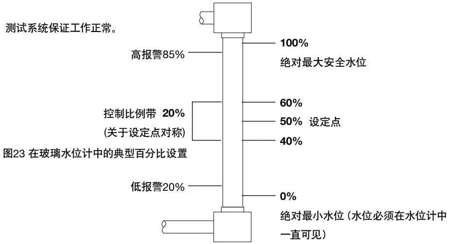
Figure 23 Typical percentage settings in gauge glass
6.4 Commissioning - Full
Follow the instructions in Section 6.2 to enter commissioning, and change settings as needed according to the ‘Main Menu Structure’ in Section 6.2.
6.4.1 Main Menu Structure
IMI displays parameters in bold font to indicate your position in the menu, and also displays the path, so it is easy to determine your position in the menu, for example:
INPUT (main menu)
LEVEL (first-level submenu)
SENSOR (position in submenu)
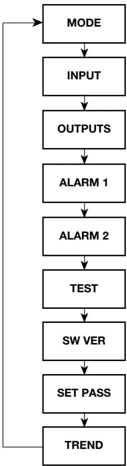
Allows the user to view and manually operate the valve (open, close, or stop) or pump on/off status (ON or OFF). Exit the menu to stop the valve or turn off the pump.
Allows the user to select sensor type and other related parameters - see INPUT submenu
Set control mode (on/off, PROP proportional), pump in (IN) or out (OUT), and other related parameters - see OUTPUTS submenu.
Set alarm 1 type (HIGH, or LOW), level, and other related parameters. See ALARM submenu.
Set alarm 2 type (HIGH, or LOW), level, and other related parameters. See ALARM submenu.
Allows the user to test different functions.
Indicates software version - useful for diagnosis.
Allows the user to select or modify the password.
Historical trend graph time unit, can be continuous - 8 minutes, 8 hours, or 8 days
6.4.2 MODE Submenu
Enter this menu (press ▶ button), allowing the user to manually control the valve or pump for commissioning.
Regulation control;
CLOSED; close valve
OPEN; open valve
STOP: stop valve, hold at current position
On/off control;
Pump on; start pump
Pump off; stop pump
Use A and V buttons to switch status, press OK to confirm selection.
Press ◀ button to exit the submenu and return to run mode.
MODE
OPEN
Note: When exiting this menu, the product will stop the pump, or stop the valve at the current position.
6.5 INPUT Submenu
6.5.1 INPUT LEVEL Submenu
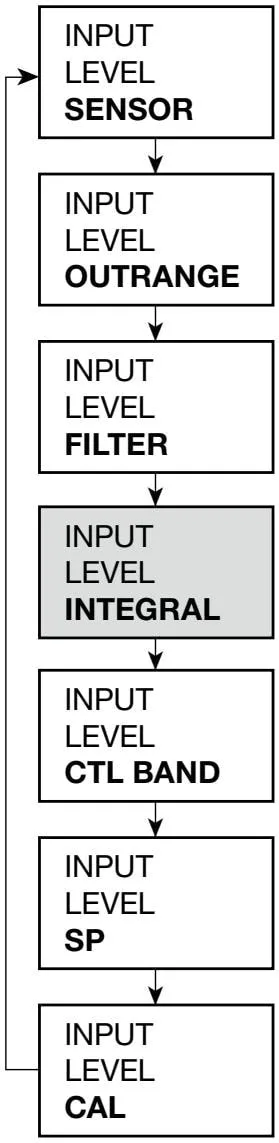
Set sensor input type - 1-6 V sensor, or 4-20 mA, for example differential pressure transmitter.
The user can select an alarm if the input signal is out of range.
Select ON or OFF
Provides damping under fluctuating conditions. The user can select 2, 8, and 16 second delays. The greater the fluctuation, the longer the delay time.
Note: Excessive delay can cause system instability.
Generally not used on steam boilers. Setting OFF provides integral action - eliminating the deviation between level and setpoint over time.
This is the proportional band for regulation control, or the on/off point for on/off systems. The midpoint is the setpoint.
Setpoint - the base point for generating the proportional band. Usually set at the midpoint between the maximum and minimum positions of the gauge glass.
Calibration. 0% and 100% calibration settings define the highest and lowest reference points of the system. For example 0% and 100% of gauge glass.
Raise the water level to the top of the gauge glass, select MAX, press OK for 3 seconds.
Lower the water level to the bottom of the gauge glass (must be visible in the gauge glass), select MIN, press OK for 3 seconds.
Note: Displays the output voltage or current for a given level. Use the MODE submenu to manually open/close the valve to assist commissioning.
6.5.2 INPUT POT Submenu
INPUT POT CAL
Calibrate VMD feedback potentiometer.
INPUT-POT-CAL-MIN
The controller will automatically drive the valve to the closed position. When the closed position is reached, press OK to confirm input.
INPUT-POT-CAL-MAX
The controller will automatically drive the valve to the 100% position. When the fully open position is reached, press OK to confirm input.
6.5.3 INPUT STEAM Submenu
INPUT STEAM OFFSET
For two-element control, provides a setpoint offset % proportional to boiler load. Each boiler requires a steam flow meter. The offset is displayed graphically.
INPUT STEAM MAX
Only available when OFFSET percentage is selected, that is, a steam flow meter is used (two-element control system). This setting allows the user to use a steam flow meter larger than the boiler’s maximum capacity.
The steam flow meter output needs to be re-adjusted to correspond to the boiler’s maximum load range. This can be obtained by the following two methods:
If possible, set the steam flow meter to 100% (20 mA) corresponding to boiler capacity. Set STEAM MAX to 100%.
Use the flow meter maximum parameter to adjust the steam flow meter output. For example, if the boiler maximum capacity is 60% of the steam flow, enter 60%.
Example 1:
Boiler maximum capacity 10000 kg/h, steam flow meter capacity 10000 kg/h - set STEAM MAX to 100%
Example 2:
Boiler maximum capacity 10000 kg/h, steam flow meter capacity 20000 kg/h - set STEAM MAX to 50%
6.5.4 INPUT WATER METER Submenu
INPUT W/METER
Can select feedwater flow meter, only available when proportional control is selected.
INPUT W/METER %
If a water flow meter is selected, at maximum boiler output, the water flow meter reading can be adjusted to 100%.
For example
If the maximum boiler capacity is 60% of the water flow meter, enter 60%.
6.5.5 OUTPUT Submenu
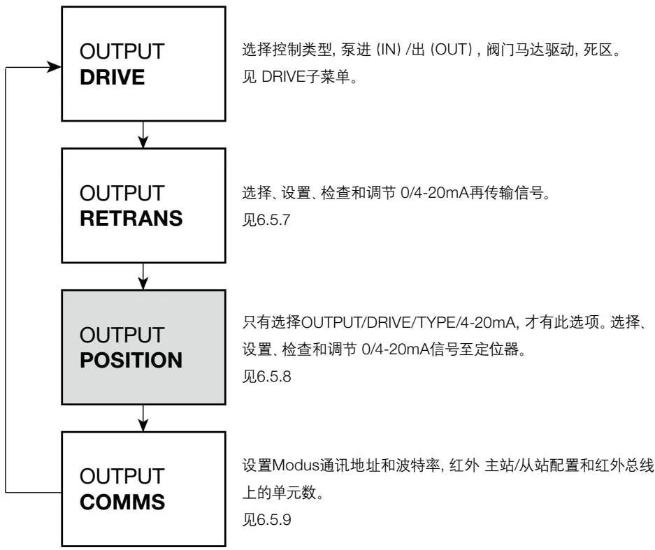
6.5.6 OUTPUT DRIVE Submenu
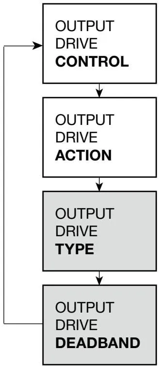
Select valve control - ON-OFF or PROP (proportional)
Select PUMP IN or PUMP OUT, that is, fill or drain control.
Only available when proportional control is selected. Select valve regulation - valve motor drive (VMD), or 4-20 mA.
Only available when proportional control is selected. Select a wider proportional band deadband for severely fluctuating boilers. Generally start setting at 10%.
6.5.7 OUTPUT RETRANS
Enables remote monitoring, recording, and display of water level.
0 or 4 mA
This menu allows the user to select the minimum setting of 0 or 4 mA. Default setting is 4 mA (if 4 mA is used, the 0 mA signal serves as a fault indication.
SET
4 mA and 20 mA retransmission levels are set as a percentage of gauge glass, typically 4 mA = 0%, 20 mA = 100%, which can be modified as needed. If the 4 mA level is set higher than the 20 mA level, the transmitter output is reversed. For example, rising water level decreases current output.
CHECK
Allows the user to adjust the 4 mA and 20 mA settings, for example calibrate VMD readings.
6.5.8 Output Position
Outputs a signal to a 4-20 mA positioner.
0 or 4 mA
This menu allows the user to select the minimum setting of 0 or 4 mA. Default setting is 4 mA (if 4 mA is used, the 0 mA signal serves as a fault indication.
SET
Retransmit 4-20 mA signal to positioner.
Typically 4 mA = 0%, 20 mA = 100% (required valve position). If 4 mA = 100%, 20 mA = 0% is set, the transmitter output is reversed.
6.5.9 OUTPUTS COMMS
Address set to 1, unless there are other units in this system.
Baud matches the baud rate of the system or bus
IR COMMS infrared, select master or slave device. See Section 6 - Communication
6.5.10 ALARM1 and ALARM2 Menus
The two alarm menus are identical.
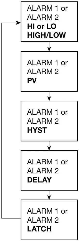
Set high or low alarm. Both alarms can be set as high alarm or low alarm, or one high alarm and one low alarm. Boiler low-level alarm regulations must be complied with.
Set the process value for alarm action, for example high alarm, 85% of gauge glass.
Damping effect - default 5%, set a higher value under severely fluctuating conditions.
Select further damping for severely fluctuating boilers (0-99 seconds). Longer delays prevent false alarm signals.
Each alarm can be latched or non-latched. If latch ON is selected, the alarm remains ON until commissioning mode is entered to cancel. Powering off will not cancel the alarm.
Latch - Warning: Each time a water level alarm occurs, with the latch function selected, the product retrieves data from internal non-volatile memory. This operation has a finite number of cycles, reducing the product’s service life.
(For example, if an alarm occurs once a day, the product can be used for approximately 13 years)
6.5.11 TEST Menu
Use diagnostic function 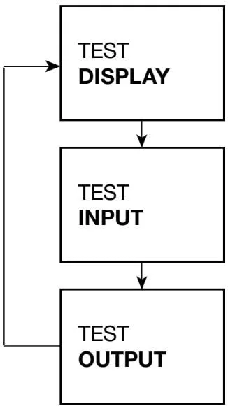
Activate all display pixels - black screen. Press button to
TEST INPUT. Press left button to cancel test and to
SW.VER
Displays the input signal for each channel.
See TEST INPUT submenu
Required configuration output
See TEST OUTPUT submenu.
6.5.12 TEST INPUT Submenu
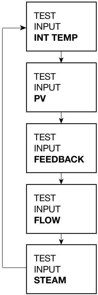
Displays the current internal device temperature in °C. Resets after leaving the menu.
Displays the mA or V of the level sensor.
Displays the voltage output of the valve feedback potentiometer (if installed).
Displays the water flow meter (if installed) mA input.
Displays the steam flow meter (if installed) mA input.
6.5.13 TEST OUTPUT Submenu
Test parameters reset to run mode values or status after 5 minutes, or select TEST/OUTPUT/CANCEL.
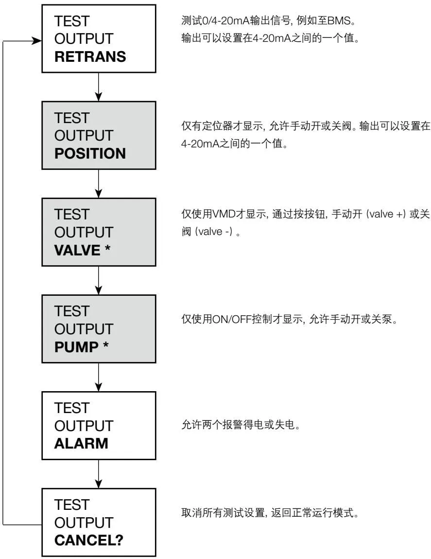
Note: VALVE or PUMP submenu display depends on control selection.
- VALVE and - VALVE, test relay ON or OFF position. Note: Select ON or OFF, return to initial submenu (+ VALVE or - VALVE)
6.5.14 SOFTWARE VERSION Submenu
SW VER
View software version - useful for fault diagnosis
6.5.15 PASS CODE Submenu
SET PASS
Allows the user to modify the password. If the default password is modified, be sure to remember the new password.
7. Communication
7.1 Infrared (IR)
Adjacent products within a certain range can communicate via infrared bus.
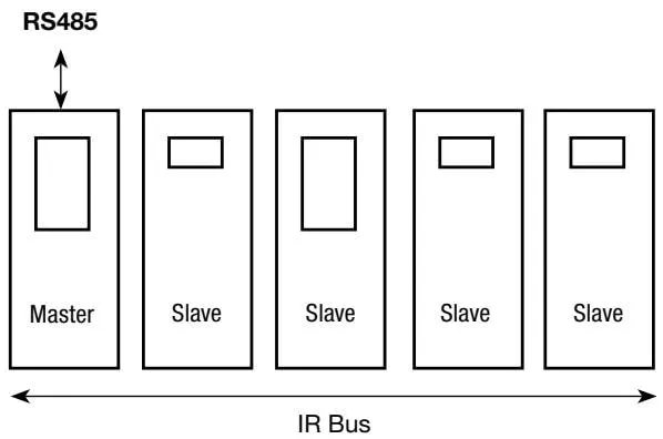
It can transmit parameters of up to 8 products to a product installed with RS485 (as shown in the figure). The LC2650 can be set as master or slave.
The product connected to the RS485 network must be installed to the left of all infrared bus slaves (Figure 30), and select ‘MASTER’ menu in ‘OUTPUT-COMMS’.
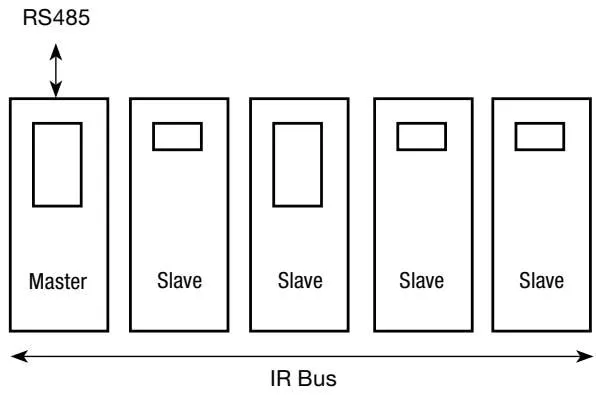
Figure 24
Two or more infrared buses can share the same chassis or DIN rail. Bus 2 will ignore bus 1. See Figure 31.
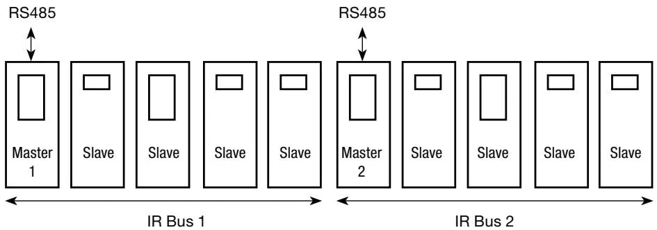
Figure 25
If a slave is to be added to an existing infrared bus, re-select ‘MASTER’.
Only one infrared master can transmit parameters to the RS485 network. If a slave is also connected to the RS485 network, then parameters are only transmitted to the RS485 network through the master.
Note: Do not obstruct the infrared light between products.
7.2 RS485 Address
An offset is added to each device’s register address (see above), depending on its position on the infrared bus, that is, the master offset is 0, the first device to the right of the master has offset 100, the next device to the right has offset 200, and so on.
| Infrared address | 1 | 2 | 3 | 4 | 5 | | 485 offset | 0 | 100 | 200 | 300 | 400 |
Figure 26
8. Maintenance
Note: Before performing any maintenance, please read Section 1 Safety Information.
Warning: Do not cover or obstruct the infrared light between products.
8.1 Cleaning Instructions:
Use a cloth dampened with water or isopropyl alcohol. Using other cleaning materials may damage the product and void the warranty.
The product requires no special servicing, preventive maintenance, or inspection. In many countries, including the UK, boiler blowdown regulations must be complied with.
When one boiler is shut down and other boilers are running, be especially careful.
8.2 Level Control
However, boiler water level control and level alarms require testing and inspection. Health and Safety Executive guidance PM5 provides general guidance. For specific guidance on Spirax Sarco systems, please refer to separate literature.
9. Fault Diagnosis
Warning:
Before starting fault diagnosis, please read Section 1 Safety Information and Section 5.1 Wiring Instructions.
Please note that there is hazardous voltage; only qualified personnel may perform fault diagnosis.
Before opening the enclosure cover, the product must be disconnected from the power supply and must be properly installed before powering up.
Failure to follow the procedures in this manual for fault diagnosis will result in a reduced safety level.
9.1 Introduction
Faults are most likely to occur during installation and commissioning. The most common fault is incorrect wiring. If the product displays a fault message after power-up, the cause of the fault must be found. To simplify and assist this process, the product has a test menu.
The product has 6 visual input channels, which can be checked to see if the product is working properly.
9.2 System Faults
| Symptom | Action |
|---|---|
| 1 Screen does not display | 1. Turn off the product power. 2. Check that all wiring is correct. 3. Check that the external fuse is normal, replace if necessary. 4. Check that the power supply voltage is within the specified range. 5. Turn on the power. If the symptom persists, return the product for inspection. Consider the possibility that the product has been damaged by power surges/spikes. Consider installing an additional AC line protection device between the product and the power supply. Position the protection device as close to the product as possible for adequate protection. |
| 2 Flashing display on and off (approximately 1 second) | 1. Turn off the product power. 2. Disconnect all signal cables. 3. Turn on the power: if the symptom persists, return the product for inspection. 4. Connect each signal cable one by one until the fault occurs. 5. Check and correct any incorrect wiring related to external sensors/transmitters and modules. Explanation: unable to start internal power supply; if voltage cannot be generated, the power turns off for approximately 1 second, then the power attempts to restart. If the fault persists, it cycles repeatedly until the fault is cleared. This is a safety function and does not damage the product. |
| 3 Product starts for a period (greater than 1 minute), then shuts down. | 1. Monitor the power supply and ensure it is continuous and within specification limits. 2. Measure the ambient temperature and ensure it is less than the specified value. 3. Investigate symptom 2. Explanation: a resettable thermal protection device has operated if one or more of the following occurs: - power drop exceeds specification. - input voltage is below specification. - ambient temperature is above specified specification. - internal power supply will shut down until the product temperature drops below 65 °C. This is a safety function and does not damage the product. |
9.3 Operating Error Messages
In run mode, any operating errors are displayed on the alarm and error screen.
| Error | Cause | Action |
|---|---|---|
| 1 Power out | Loss of power during operation | 1. Turn off the product power. 2. Check that all wiring is correct. 3. Check that the power supply is secure, i.e., will not be interrupted. 4. Re-power. |
| 2 Setup menu time out | No button pressed within 5 minutes after entering commissioning mode | 1. If necessary, re-enter commissioning mode. |
| 3 Outrange high | Input signal increased beyond product specification | 1. Measure the input current or voltage with an instrument; do not exceed product specification. See Section 6 - Input Technical Data |
| 4 Outrange low | Input signal decreased below product specification | 1. Measure the input current or voltage with an instrument; do not exceed product specification. See Section 6 - Input Technical Data |
| 5 Alarm 1 | A high or low alarm has occurred, check alarm 1 settings | 1. Check boiler operation 2. Check boiler alarm settings and operation, and the boiler feedwater system. 3. Check alarm 1 settings |
| 6 Alarm 2 | A high or low alarm has occurred, check alarm 2 settings | 1. Check boiler operation 2. Check boiler alarm settings and operation, and the boiler feedwater system. 3. Check alarm 2 settings |
| 7 Alarm is latched! | For safety, some errors latch the alarm relay. Only the display message can be cleared from the screen | 1. Enter commissioning mode, enter the password (settings), then all latched alarms are cancelled. |
10. Technical Information
10.1 Technical Assistance
Contact your local Spirax Sarco representative.
10.2 Returning Faulty Equipment
Please return all parts of the product to your local Spirax Sarco representative. Please ensure all parts are well packaged for transport (preferably using the original carton).
Please provide the following information when returning equipment:
- Your name, company name, address and telephone number, order number and invoice, and return delivery address.
- Equipment description and serial number.
- Detailed description of the fault or repair required.
- If the equipment is returned within the warranty period, please indicate:
Date of purchase.
Original order number.
10.3 Power Supply
| Supply voltage range | 99 to 264 V AC at 50/60 Hz | | Power consumption | 7.5 W |
10.4 Environment
| General | Indoor use | | Maximum altitude | 2000 m above sea level | | Ambient temperature range | 0 - 55 °C (32 - 131 °F) | | Maximum relative humidity | 80% at 31 °C (88 °F) linearly decreasing to 50% at 40 °C (104 °F) | | Overvoltage | III | | Pollution degree | 2 (as supplied) 3 (when installed in an enclosure) - minimum IP54 or UL50 / NEMA Type 3, 3S, 4, 4S, 6, 6P or 13. See Section 4, Mechanical Installation | | Sealing rating (front panel only) | NEMA Type 4 hose down only (UL certified) approved and compliant with IP65 (TRAC GLOBAL certified) | | Panel screw torque | 1 - 1.2 Nm | | LVD (Safety) | Electrical safety EN 61010-1 UL61010-1, UL508, Clause 23.2 CAN/CSA C22.2 No.61010-1. | | EMC | Immunity/Emission suitable for heavy industrial locations | | Housing Material | Polycarbonate | | Front Panel Material | Silicone rubber, 60 shore. | | Solder | Tin/lead (60/40%) |
10.5 Cables/Data Lines and Connectors
Power and Signal Connectors
| Terminal | Plug-in terminal block with screw connector. (Use only connectors provided by Spirax Sarco - otherwise the safety level will be reduced) | | Cable size | 0.2 mm² (24 AWG) to 2.5 mm² (14 AWG). | | Stripping length | 5 - 6 mm |
Sensor and feedback circuit, steam flow meter and water flow meter cables/wires
| Type | High temperature | | Shield type | Shielded | | Number of cores | 3 cores (CP20/PA20), 2 or 3 (4-20 mA transmitter) | | Cable size | 1 - 1.5 mm² (18 - 16 AWG) | | Maximum length | 100 m | | Recommended | Pirelli (Prysmian) FP200, Delta Crompton Firetuf OHLS |
0/4-20 mA output cables/wires
| Type | Twisted pair | | Shield type | Shielded | | Number of cores | 1 | | Cable size | 0.23 - 1 mm² (24 - 18 AWG) | | Maximum length | 100 m | | Recommended type | Various |
RS485 communication
| Type | EIA RS485 twisted pair | | Shield type | Shielded | | Number of pairs | 2 or 3 | | Cable size | 0.23 mm² (24 AWG) | | Maximum length | 1200 m | | Recommended type | Alpha Wire 6413 or 6414 |
Cables: LAN Cat 5 or Cat 5E ScTP (shielded), FTP (foil), or STP (shielded) can be used, but limited to within 600 m.
10.6 Input Technical Data
Level Probe Voltage
| Minimum voltage | 0 Vdc or 1 V (overrange selection) | | Maximum voltage | 6 Vdc (absolute maximum = 7 Vdc) | | Input impedance | 28 kΩ | | Accuracy | 5% FSD operating range | | Repeatability | 2.5 FSD operating range | | Resolution | Approximately 0.15 mV | | Sampling time | 260 Hz |
4-20 mA(s)
| Minimum current | 0 mA | | Maximum current | 22 mA | | Input impedance | 110 Ω | | Accuracy | 5% FSD operating range | | Repeatability | 2.5% FSD operating range | | Resolution | Approximately 0.15 mV | | Sampling time | 260 Hz |
Level ‘Overrange’ Alarm - Voltage
| Minimum alarm level | < 0.2 Vdc | | Minimum recovery level | > 1 Vdc | | Maximum alarm level | > 6.5 Vdc | | Maximum recovery level | < 6 Vdc |
Level ‘Overrange’ Alarm - Current
| Minimum alarm level | < 2.5 mA | | Minimum recovery level | > 4 mA | | Maximum alarm level | > 21 mA | | Maximum recovery level | < 20 mA |
10.7 Output Technical Data
24 Vdc Power Supply
| Maximum voltage | 32 Vdc (no load, open circuit) | | Maximum current | 25 mA | | Ripple voltage | 10 mV at 264 V, full load |
4-20 mA(s)
| Minimum current | 0 mA | | Maximum current | 20 mA | | Open circuit voltage (maximum) | 19 Vdc | | Resolution | 1% FSD | | Maximum output load | 500 ohms | | Isolation | 100 V | | Output rate | 10/second |
Relay(s)
| Contacts | 2 × single-pole changeover relays (SPCO) | | Rated voltage (maximum) | 250 Vac | | Resistive load | 3 amp at 250 Vac | | Inductive load | 1 amp at 250 Vac | | AC motor load | 1/4 HP (2.9 amp) at 250 Vac 1/10 HP (3 amp) at 120 Vac | | Pilot duty | C 300 (2.5 amp) - control circuit/coil | | Electrical life (operations) | 3 × 10⁵ or greater, depending on load | | Mechanical life (operations) | 30 × 10⁶ |
RS485
| Physical layer 485 | RS485 4-wire full-duplex or 2-wire half-duplex | | Protocol layer | Modbus RTU format | | Isolation | 60 Vac/dc | | Receiver unit load | 1/8 (256 devices - maximum) - all 256 devices have 1/8 load input | | Output rate | Up to 10 frames/second |
Infrared
| Physical layer | IrDA | | Baud | 38400 | | Range | 10 cm | | Working angle | 15° | | Eye safety information | Summary: EN 60825-12: 2007 Safety of laser products - does not exceed Class 1 emission limit (AEL) |
10.8 Parameter Settings/Default Settings
The default settings in the table below can be used in ‘Quick Setup’ - see Section 6
10.8.1 MODE MENU Proportional Control
Allows manual open, close, or stop of valve.
| Range | Open, close, or stop | | Default | Stop |
On/Off Control
Allows manual pump on or pump off
| Range | Pump on, off | | Default | Pump off |
10.8.2 INPUT Menu
LEVEL-SENSOR (input signal/type)
| Range | 1-6 or 4-20 mA | | Default | 1 - 6 V |
LEVEL - OUTRANGE
| Range | ON or OFF | | Default | OFF |
LEVEL - FILTER
| Range | 2, 8, or 16 | | Default | 2 | | Unit | seconds |
LEVEL - INTEGRAL (integral or reset time)
| Range | 5 - 300 | | Default | OFF, select ON then 120 | | Resolution | 1 | | Unit | seconds |
LEVEL- CTL BAND (control proportional band)
| Range | 5 - 100 (interactive with steam offset and setpoint, control band cannot exceed 100%) | | Default | 20 | | Resolution | 1 | | Unit | % |
LEVEL-SP (setpoint)
| Range | 3 - 97 (interactive with steam offset and setpoint, control band cannot exceed 100%) | | Default | 50 | | Resolution | 1 | | Unit | % |
STEAM - OFFSET (increase water level % due to 100% steam load)
| Range | 0 - 94 (Interactive with steam offset and SP. control band cannot exceed 100%) | | Default | 0 | | Resolution | 1 | | Unit | % |
STEAM - MAX (corresponds to maximum steam load, adjusts steam flow meter output.)
| Range | 10 - 100% | | Default | 100 | | Resolution | 1 | | Unit | % |
WATER METER (feedwater flow meter)
| Range | OFF or ON | | Default | OFF |
WATER METER - ON - MAX (corresponds to maximum steam load, adjusts feedwater flow meter output.)
| Range | 10 - 100% | | Default | 100 | | Resolution | 1 | | Unit | % |
10.8.3 OUTPUT Submenu
COMMS-ADDRESS (MODBUS communication)
DRIVE - CONTROL
| Range | PROP or ON/OFF | | Default | PROP |
DRIVE - ACTION
| Range | PUMP IN or OUT | | Default | PUMP IN |
DRIVE - TYPE
| Range | VMD or 4-20 mA | | Default | VMD (valve motor drive) |
DRIVE - DEADBAND
| Range | 5 - 20 (relay hysteresis = 1%) | | Default | 10 | | Resolution | 1 | | Unit | % |
RETRANS - 0 or 4 mA
| Range | 0 or 4 mA | | Default | 4 mA |
RETRANS - SET - 4 mA
| Range | 0 - 100 | | Default | 0 | | Unit | % |
RETRANS - SET - 20 mA
| Range | 0 - 100 | | Default | 100 | | Unit | % |
RETRANS - CHECK - 4 mA
| Default | 4.00 | | Resolution | 0.01 | | Unit | mA |
RETRANS - CHECK - 20 mA
| Default | 20.00 | | Resolution | 0.01 | | Unit | mA |
POSITION (positioner) 0 or 4 mA
| Range | 0 or 4 mA | | Default | 4 mA |
POSITION (positioner) SET - 4 mA
| Range | 0 - 100 | | Default | 0 | | Unit | % |
POSITION (positioner) SET - 20 mA
| Range | 0 - 100 | | Default | 100 | | Unit | % |
POSITION (positioner) - CHECK - 4 mA
| Default | 4.00 | | Resolution | 0.01 | | Unit | mA |
POSITION (positioner) RETRANS CHECK - 20 mA
| Default | 20.00 | | Resolution (steps) | 0.01 | | Unit | mA |
COMMS - ADDRESS
| Range | 001 - 247 | | Default | 001 |
COMMS - BAUD
| Range | 1200, 9600 or 19200 | | Default | 9600 | | Unit | BAUD or bytes/second |
COMMS-IR (infrared)
| Range | Master or slave | | Default | Slave |
COMMS - IR UNITS IN NETWORK
| Range | 1 - 8 |
ALARM1 or 2 Menu
HI or LO
| Range | HIGH or LOW | | Default | HIGH (alarm 1) and LOW (alarm 2) |
LEVEL%
| Range | 0 - 100 (interactive with HYST) | | Default | 85% (HIGH), or 20% (LOW) | | Resolution (steps) | 1 | | Units | % |
HYST (hysteresis)
| Range | 0 - 100 (interactive with HYST) | | Default | 5 | | Resolution (steps) | 1 | | Units | % |
DELAY (process variable alarm delay)
| Range | 0 - 99 | | Default | 0 | | Resolution (steps) | 1 | | Units | seconds |
LATCH
| Range | OFF or ON | | Default | OFF |
TEST Menu
DISPLAY
| Range | Black-on-white or white-on-black | | Default | Black-on-white |
INPUT-INT TEMP (maximum internal temperature of electronic product)
| Range | -40 to 85 °C or -40 to 185 °F | | Resolution | 1 | | Unit | °C or °F |
INPUT - LEVEL
| Range | 0.00 - 7.00 | | Resolution | 0.01 | | Unit | dc voltage |
INPUT-FEEDBACK (VMD feedback potentiometer from valve)
| Range | 0.00 - 2.26 | | Resolution | 0.01 | | Unit | dc voltage |
INPUT-FLOW (from water flow meter)
| Range | 0.00 - 22.73 | | Resolution | 0.01 | | Unit | dc milliamps |
INPUT-STEAM (from steam flow meter)
| Range | 0.00 - 22.73 | | Resolution | 0.01 | | Unit | dc milliamps |
OUTPUT-RETRANS (manually set 4-20 mA output)
| Range | 4 - 20 mA | | Default | 20.00 | | Resolution | 0.01 | | Unit | mA |
OUTPUT-POSITION (manually set 4-20 mA output)
| Range | 4 - 20 mA | | Default | 20.00 | | Resolution | 0.01 | | Unit | mA |
OUTPUT-VALVE +VALVE or -VALVE or PUMP (manually control valve)
| Range | ON or OFF | | Default | ON |
Press OK button to activate relay - select cancel or after 5 minutes, automatically control relay.
OUTPUT-ALARM (manually energize or de-energize relay)
| Range | ON or OFF | | Default | ON |
Press OK button to activate relay - select cancel or after 5 minutes, automatically control relay.
SET PASS Menu (set password)
| Range | 0000 - 9999 | | Default | 7452 | | Resolution | 1 |
TREND Menu (set time unit)
| Range | MINS, HRS, DAYS | | Default | MINS |
11. Appendix
Modbus Protocol Overview
Format: Byte
| Start | 1 bit | | Data | 8 bits | | Parity | 0 bits | | Stop | 1 bit |
Format: Request Frame
| Address | 1 byte | | Function code | 1 byte | | Starting address | 2 bytes | | Number of registers | 2 bytes | | Cyclic redundancy check (CRC) | 2 bytes | | Total | 8 bytes |
Format: Response Frame
| Address | 1 byte | | Function code | 1 byte (or error code = function code plus 128) | | Byte count | 1 byte (or exception code, see below) | | Register | 2 bytes of data, most significant | | Error check (CRC) | 2 bytes | | Total | 7 bytes total if correct (or 5 bytes if error) | | Only function code 03, ‘Read holding registers’ is allowed. | |
Note: When the device is an infrared slave, infrared master-slave communication generates a temporary error. Add an offset +32768 to the master’s database identity value.
Parameter and Register Data
| Register | Parameter |
|---|---|
| 0 | 3 - identity |
| 1 | Water level % |
| 2 | Setpoint (SP) |
| 3 | Proportional band (CB) μS/cm or PPM (general data) |
| 4 | Alarm 1 |
| 5 | Alarm 1 relay |
| 6 | Alarm 2 |