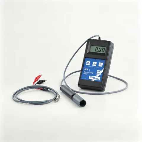

1. Conductivity measurement
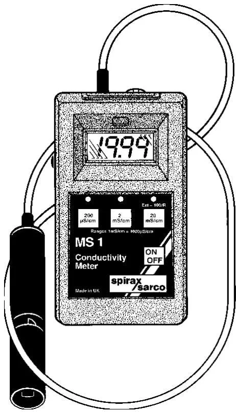
The instrument has an on/off button and a three-position range selector switch: 0-200 μS/cm, 0-2 mS/cm, and 0-20 mS/cm (1 mS/cm = 1000 μS/cm). An indicator lamp shows the range currently selected.
Ensure that the sample temperature is as close as possible to 25°C and does not exceed 45°C.
Switch on the instrument and use the range selector switch on the right to select the highest range: 0-20 mS/cm.
Immerse the sensor in the sample with the protective sleeve fitted. The immersion depth must not exceed half the length of the sensor. Wait 15 seconds for temperature compensation to take effect.
Read the display.
If a more accurate reading is required, switch to the next lower range.
If the current range cannot provide a reading, the display will show “1”.
When the display shows “1”, switch the range switch to the next higher range.
Example: sensor in tap water at 25°C:
| Selected range | Reading | × 1000 = μS/cm |
|---|---|---|
| 20 mS/cm | 0.52 mS/cm | 520 μS/cm |
| 2 mS/cm | 0.517 mS/cm | 517 μS/cm |
| 200 μS/cm | 1 | N/A |
After measurement, rinse the sensor and switch off the instrument; the instrument will also switch off automatically after approximately 5 minutes.
2. TDS measurement
The conductivity meter can be used to estimate the TDS value of a water sample. For neutral water samples, the temperature-compensated conductivity reading can be converted to TDS (ppm) using the following formula:
TDS (ppm) = conductivity reading (μS/cm) × 0.7
3. Boiler water sampling
Obtaining a representative boiler water sample is essential for analysis. The initial water taken from a water level gauge drain or an external water level control column is mainly condensate and is a relatively pure sample. This condensate must be drained before a true sample can be obtained.
A sample cooler should be used when sampling boiler water. If water is taken directly from the boiler, the pressure drop will cause some of the water to flash into steam and escape. This is very dangerous, and the flash losses will make subsequent analysis inaccurate. Using a sample cooler also brings the sample temperature close to 25°C and saves time.
4. Neutralizing boiler water samples
Acids and alkalis have a significant effect on conductivity. Therefore, before measuring the TDS of a boiler water sample, the alkalinity of the sample must first be neutralized.
The procedure is as follows:
Add a few drops of phenolphthalein indicator to the cooled sample; if the sample is alkaline, the solution will turn purple.
Add acetic acid (usually a 5% solution) drop by drop to neutralize the sample, stirring continuously until the purple color disappears.
Measure the conductivity and convert it to a TDS value as described in Section 2.
If neutralization cannot be carried out on site, the boiler TDS value can be estimated using the following formula:
TDS = conductivity reading (μS/cm) × 0.5
5. Maintenance
The sensor should be cleaned frequently according to use: remove the protective sleeve, gently clean the carbon electrodes with a brush and ordinary kitchen detergent, rinse thoroughly with tap water, and refit the protective sleeve.
Replace the battery when the display shows a low-battery warning.
Open the battery compartment on the back of the instrument to access a single 9V battery (PP3 or equivalent).
The instrument has no other serviceable parts. The sensor is permanently connected to the instrument; if it is damaged, the complete instrument must be returned for repair.
6. Using the extension lead
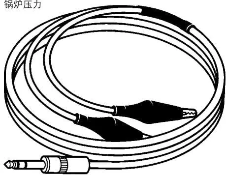
The instrument is supplied with an extension lead for measuring the AC resistance of an installed conductivity sensor in order to check its condition.
To use the extension lead, plug one end into the instrument and connect the other end directly to the sensor terminals using crocodile clips. Press the 20 mS/cm range switch. The AC resistance value (Ω) equals 100 divided by the displayed reading.
Example:
Displayed reading 5.00
Ω = 100 ÷ 5.00 = 20 Ω
The minimum measurable resistance is 5 Ω.
7. Determining the condition of the sensor
To determine the condition of the sensor, first determine its cell constant (which is related to the liquid conductivity and the sensor resistance).
To determine the cell constant:
Multiply the conductivity at 25°C by the factor in the table to obtain the conductivity at the boiler temperature.
| Boiler pressure (bar g) | 5 | 7 | 10 | 15 | 20 | 32 |
|---|---|---|---|---|---|---|
| Conductivity factor | 3.68 | 3.91 | 4.18 | 4.53 | 4.8 | 5.28 |
- Divide the conductivity reading (μS/cm) by 1000000 to convert it to S/cm.
- Multiply the resulting value by the sensor resistance (Ω, measured as described in Section 6) to obtain the cell constant.
Typical cell constants for sensors in BCS1, 2, or 4 systems are approximately 0.3; in BCS3 systems, approximately 0.3 to 0.7.
If the cell constant of a sensor in a BCS1, 2, or 4 system is greater than 0.7, or greater than 1.0 in a BCS3 system, the sensor may have failed and should be removed for inspection, cleaned, or replaced if necessary.
A low cell constant indicates that the sensor is working well; a high cell constant indicates that the conductivity at the sensor tip is already very low, possibly due to scaling.
An extremely low cell constant indicates an internal short circuit. The farther the sensor tip is from the boiler, the greater the cell constant.
Example:
A BCS3 system is installed on a boiler operating at 10 bar g (saturated steam temperature 184°C).
The conductivity meter reading for an unneutralized sample at 25°C is 4800 μS/cm.
The sensor resistance measured using the conductivity meter and extension lead is 20 Ω.
- Multiply the conductivity by the factor for a 10 bar boiler in the table above: 4800 × 4.18 = 20064
- Divide the result by 1000000 to convert it to S/cm: 20064 ÷ 1000000 = 0.020064
- Multiply the resulting value by the sensor resistance to obtain the cell constant: 0.020064 × 20 = 0.40128
The cell constant of this sensor is within the range of 0.3 to 0.7, so no further inspection is required.
8. Calibration
The instrument is calibrated at the factory and requires no adjustment during normal use.
If calibration with a standard solution is required or higher accuracy is desired, unscrew the plug on the left side of the display and adjust the potentiometer with a small screwdriver. The calibration adjustment range is 20 turns ±20% (approximate).
Calibration does not affect resistance measurements made with the extension lead.
Related products
See the product introduction, technical specifications, and supporting documentation for the MS1 conductivity meter.