1. Safety Information
Compliance with the operating instructions and correct installation, commissioning, use, and maintenance by professionally qualified personnel is the sole guarantee of safe operation of this product (see Section 1.11). Installation must comply with general installation and safety guidelines for piping and equipment, as well as correct use of tools and safety equipment.
In the United Kingdom, the IEE Wiring Regulations (BS 7671) must be followed; in other regions, the corresponding regulations must be followed.
All wiring materials and procedures must comply with the corresponding EN and IEC standards.
Warning
This product is designed and manufactured to withstand external forces during normal use. If this product is not used as a boiler controller or the installation process does not follow the instructions in this manual, during product modification or repair it may:
- Cause personal injury or death;
- Cause product/property damage;
- Invalidate the CE mark;
These guidelines should always be kept in a safe place near the boiler controller installation location.
Warning
LP30 level sensor and LC3050 level controller
LP31 level sensor and LC3050 level controller
The above products comply with the European Pressure Equipment Directive 97/23/EC and bear the CE mark. They are classified as safety accessories, Category IV under the directive.
This product complies with the Electromagnetic Compatibility Directive 2004/108/EC and meets all its requirements.
The product meets all requirements of the directive and is suitable for Class A environments (e.g., industrial). The LC3050 meets the directive requirements by satisfying the control standards:
EN61326-1:2006 Electrical equipment for measurement, control, and laboratory use - EMC requirements Part 1: General requirements. In addition, the LC3050 meets the EMC requirements of the following standards:
EN 12953-9: 2007 - Shell boilers Part 9: Requirements for limiting devices for boilers and ancillary equipment.
EN 12952-11: 2007 - Water-tube boilers and auxiliary installations Part 11: Requirements for limiting devices for boilers and ancillary equipment. VdTÜV directive Water Level 100:2006.
Under the following conditions, this product may be exposed to interference exceeding heavy industry immunity limits:
The product or its connecting cables are near wireless transmitters;
The main power supply has interference. If the power supply may have interference, a line protector should be installed. The protector functions include filtering, rectification, and surge protection.
Using mobile radios and mobile phones within approximately 1 meter of the product or its connecting cables may cause interference. However, the actual safe distance varies depending on the site environment.
The product, as a water level alarm controller type test, complies with the following standards:
- VdTÜV Water Level Control and Limiting Equipment 100 (07: 2006)
If the product is not used according to IMI instructions, the protection provided will be weakened.
Electrostatic Discharge (ESD) Prevention
Care must be taken to prevent electrostatic discharge to avoid product damage.
For Steam Boiler Level Control and Level Limiting
The product must be selected, installed, operated, and tested according to the following:
Local or national standards and regulations
Guidance manuals (UK Health and Safety Directive PM5)
Requirements of the approving authority
Boiler inspection authority
Boiler manufacturer’s instructions
Steam boilers must be installed with two independent low water level limiting/alarm systems. Level sensors must be installed in separate protection tubes/chambers, with adequate space between the sensor end and the ground terminal.
Each sensor must be connected to an independent controller. During a low alarm, the alarm relay must cut off the boiler heating system.
The high water level alarm must be part of the water level control, or a separate system. If safety requirements are considered, a separate high water level alarm system must be installed.
In this case, during a high water level alarm, the relay must simultaneously cut off the boiler feedwater and heating system. All boiler water level limiting/alarms require periodic functional testing.
Level sensing probes and controllers are only part of the safety system. A complete system also requires other circuits (wiring, relays, alarm bells/lights).
Continuous safe and correct operation of water level control and limiting systems requires the use of appropriate water treatment. Please consult an authoritative water treatment company.
Symbols
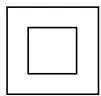
The device uses double or reinforced insulation protection;

Functional ground terminal, ensures normal product operation; not used to guarantee electrical safety;
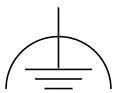
Safety ground
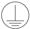
Safety ground
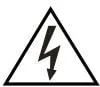
Caution, risk of electric shock;
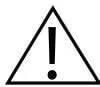
Caution, danger, please refer to relevant documentation;
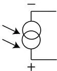
Opto-isolated current source signal;

Caution, the circuit board is susceptible to electrostatic discharge. Do not touch the circuit board without anti-static equipment.

AC, alternating current
1.1 Preparation for Use
i) Check that the product is suitable for the fluid being detected. ii) Check the suitability of materials, and the maximum and minimum values of pressure and temperature; if the maximum operating range of the product is lower than that of the system where it is to be installed, or if product failure may lead to dangerous over-temperature or over-pressure conditions, safety devices must be installed in the system to protect against such exceedances. iii) Determine the correct product installation location and fluid flow direction; iv) Spirax Sarco products cannot withstand additional stress; the installer should consider system stress and take appropriate preventive measures to reduce stress. v) Before installing the product in steam or high-temperature media, remove all connection port protection caps and the nameplate protective film.
1.2 Access
Before performing any operation, ensure safe access; if necessary, a safe working platform (with appropriate protection) is required. If necessary, arrange suitable lifting equipment.
1.3 Lighting
Ensure adequate lighting, especially where detailed or complex operations are performed.
1.4 Hazardous Liquids or Gases in Piping
Consider in advance the fluids that may exist or already exist in the piping; factors to consider include: flammability, health hazards, and temperature limits.
1.5 Hazardous Environment Around the Product
Consider: explosive environments, oxygen deficiency (e.g., in vessels or pits), hazardous gases, extreme temperatures, hot surfaces, fire hazards (during welding), excessive noise, and moving mechanical equipment.
1.6 System
Consider the impact of the planned operation on the entire system. Will the planned operation (e.g., closing shut-off valves, cutting power) cause danger to other parts of the system or any personnel?
Danger may arise from the shutdown of discharge or protection devices, or the cancellation of controls or alarms. Shut-off valves should be opened and closed slowly to avoid system oscillation.
1.7 Pressure Systems
Ensure that all pressure has been isolated and safely vented to atmospheric pressure. Consider double isolation and locking and tagging of closed valves. Even when the pressure gauge reads zero, the system cannot be considered pressure-free.
1.8 Temperature
After isolation, allow time for cooling to ambient temperature to avoid burns.
1.9 Tools and Spare Parts
Before starting use, ensure that suitable tools and consumable spare parts are available. Use only original spare parts provided by Spirax Sarco.
1.10 Protective Clothing
Consider whether you or nearby personnel need to wear protective clothing to prevent hazards such as: chemicals, high/low temperatures, radiation, noise, falling objects, and eye and face injuries.
1.11 Work Permit
All operations must be performed or supervised by suitable personnel qualified for the work. Installation and maintenance personnel must be trained on how to correctly operate this product according to the installation and maintenance guide.
Comply with formal “work permit” systems; operations must be strictly performed as described above. If no such system exists, it is recommended that the responsible person understand the operation being performed and, if necessary, arrange an assistant responsible for safety.
If necessary, post “caution” notices.
1.12 Manual Handling
Manual handling of large or heavy objects can cause danger or personal injury. Directly lifting, pulling, pushing, raising, or supporting loads by human force can cause personal injury, especially to the back. It is recommended that customers conduct a risk assessment considering the task, personnel, workload, and working environment, and adopt appropriate handling methods according to the working environment.
1.13 Residual Hazards
Under normal conditions, the outer surface of the product may be hot.
Many products do not have self-draining functions. Extreme care should be taken when disassembling products.
1.14 Freezing
When the product is exposed to sub-zero environments, valves without self-draining functions are at risk of freezing and must be protected.
1.15 Disposal
When disposing of this product, appropriate preventive measures should be taken according to local regulations.
Unless otherwise noted in the installation and maintenance guide, this product is recyclable and, if properly disposed of, has no harmful effect on the ecological environment.
1.16 Returns
Customers and stockists are reminded that, in accordance with EC Health, Safety and Environmental legislation, when returning products to Spirax Sarco, customers must provide information on hazards and the precautions taken when handling contaminated residues or mechanical damage that may pose risks to health, safety, or the environment. Safety data sheets for any hazardous or potentially hazardous substances must be provided in writing.
2. Product and Delivery Information
2.1 Introduction
The LC3050 is used for high/low level alarming of conductive fluids.
It can be used on steam or hot water boilers up to 239 °C at 32 bar g.
The LC3050 is defined as a specially designed electronic water level limiter, complying with EN12952-11-2007.
Used with Spirax Sarco high/low, self-monitoring, high-precision level sensors.
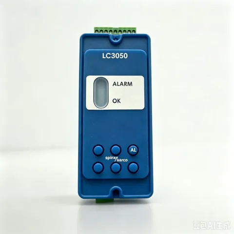
The LC3050 has dual voltage power supply, 220/240 Vac or 110/120 Vac, with the following LED indicators:
Green - Normal level
Red - Level alarm - boiler water level low/high
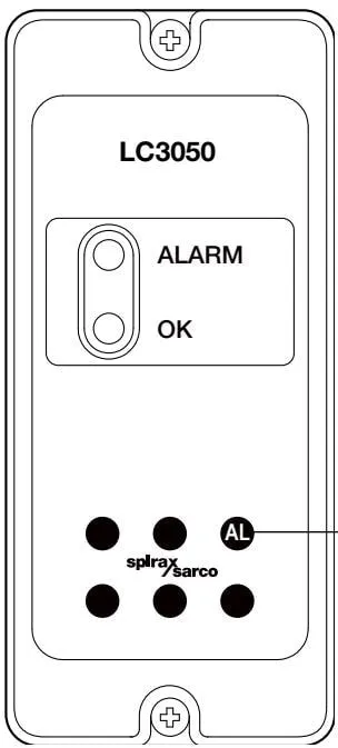
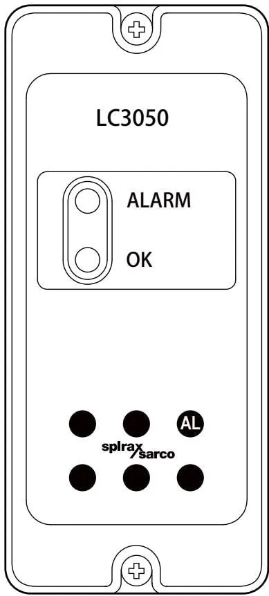
Figure 1 Button explanation
Warning: In many countries, steam boilers with limited operational supervision require two self-monitoring level sensors and controllers to provide two independent low level alarms. It is also recommended to install a high level alarm, which is mandatory in some countries.
Warning: Minimum conductivity 30 μS/cm or 30 ppm
The product can be panel, DIN rail, or baseplate mounted.
The front panel has two LEDs indicating normal and alarm conditions, and a test button.
Press and hold to test the alarm.
Other buttons are not used.
2.2 LC3050 Cyclic Self-Test Function
Every few seconds, an internal probe fault is simulated to perform automatic cyclic testing of the probe, probe cable, and controller.
A test button is provided for complete testing of the sensor, controller, and related circuits.
If required, remote test button wiring can be reserved.
2.3 Equipment Delivery, Transport, and Storage
Factory Shipment
Before shipment from the factory, the product has been tested, calibrated, and inspected to ensure normal operation.
Receipt
Upon delivery, each carton should be inspected to avoid external damage. Any visible damage should be immediately recorded on the delivery note. Carefully open the carton and inspect the product for damage. If there is damage or loss, immediately notify Spirax Sarco and provide details. Additionally, notify the transport personnel of the damage and ask them to inspect the damaged product and packaging carton on site.
Storage
If storage is required before installation, ambient temperature 0-65 °C, 10%-90% relative humidity (non-condensing). Before installation and power connection, ensure there is no condensation inside the product.
3. System Overview
The LC3050 generally uses one alarm relay, configured for level alarms beyond the normal range for steam or hot water boilers, water tanks, or vessels.
Input
The product accepts signals from the LP30 low level sensor or LP31 high level sensor.
Function
The LC3050 compares the resistance to ground from the sensor through the water to the boiler or vessel shell.
A change in water level causes the resistance to exceed the setpoint, and after a preset delay a timer changes the state of the internal relay. The signal is used to trigger an alarm.
The compensation probe on the sensor compensates for any ground leakage caused by scaling, fouling, or internal water vapor, to ensure that an alarm signal is issued even under adverse conditions.
The product can be connected to adjacent boiler room controllers via infrared (Spirax Sarco products only). The LC3050 is set only as a slave - see Section 7, Communication.
4. Mechanical Installation
Note: Before installing this product, please read the safety information in Section 1.
Note: There must be 15 mm spacing between multiple products to facilitate air circulation. Do not attempt to open the product:
The product is sealed, with no replaceable parts or internal switches. Do not cover or obstruct the infrared light directly between products.
The product must be installed in a suitable industrial control panel or fireproof enclosure, providing impact and environmental protection. Minimum IP54 (EN60529) or Type 3, 3S, 4, 4X, 6P, and 13 (UL50/NEMA250) is required.
4.1 Environmental Conditions
The product installation environment should reduce the effects of heat, vibration, and electrical interference (refer to Section 1 - ‘Safety Information’).
Without additional weather protection, do not install the product outdoors.
4.2 Installation on DIN Rail
Clips and a set of self-locking screws are provided with the product for installation on a 35 mm DIN rail. On the rear of the housing, there are two sets of holes to determine the height position. The clip head can be adjusted to change position. Install the clip head in one set of holes and secure with the two provided screws. Ensure the clip and rail are clamped.
Note: Use only the screws provided with the product
4.3 Installation on Baseplate
On the baseplate, drill holes as shown in Figure 2.
Install the product on the baseplate, securing with two screws, nuts, and washers through the upper and lower slots.
Note: Do not drill holes in the product housing or use self-locking screws.
4.4 Installation on Cut Panel
(If using a frame, minimum panel thickness is 1 mm)
The product has integral threaded sockets at the top and bottom (M4 x 0.7)
Two M4 x 25 mm screws, washers, and instrument frames are provided

Note: Do not use screws longer than 25 mm to avoid electric shock.
- Cut the panel according to the dimensions in Figure 15, and drill screw holes as indicated.
- After removing the backing from the washers, place them on the front of the product.
- Frames can be used to improve appearance. If required, install them on the outside of the panel.
- Install the product from the rear of the panel, securing with screws, washers (and instrument frames).
- Tighten M4 screws to 1.0 - 1.2 Nm
Note: Do not drill holes in the product or use self-locking screws
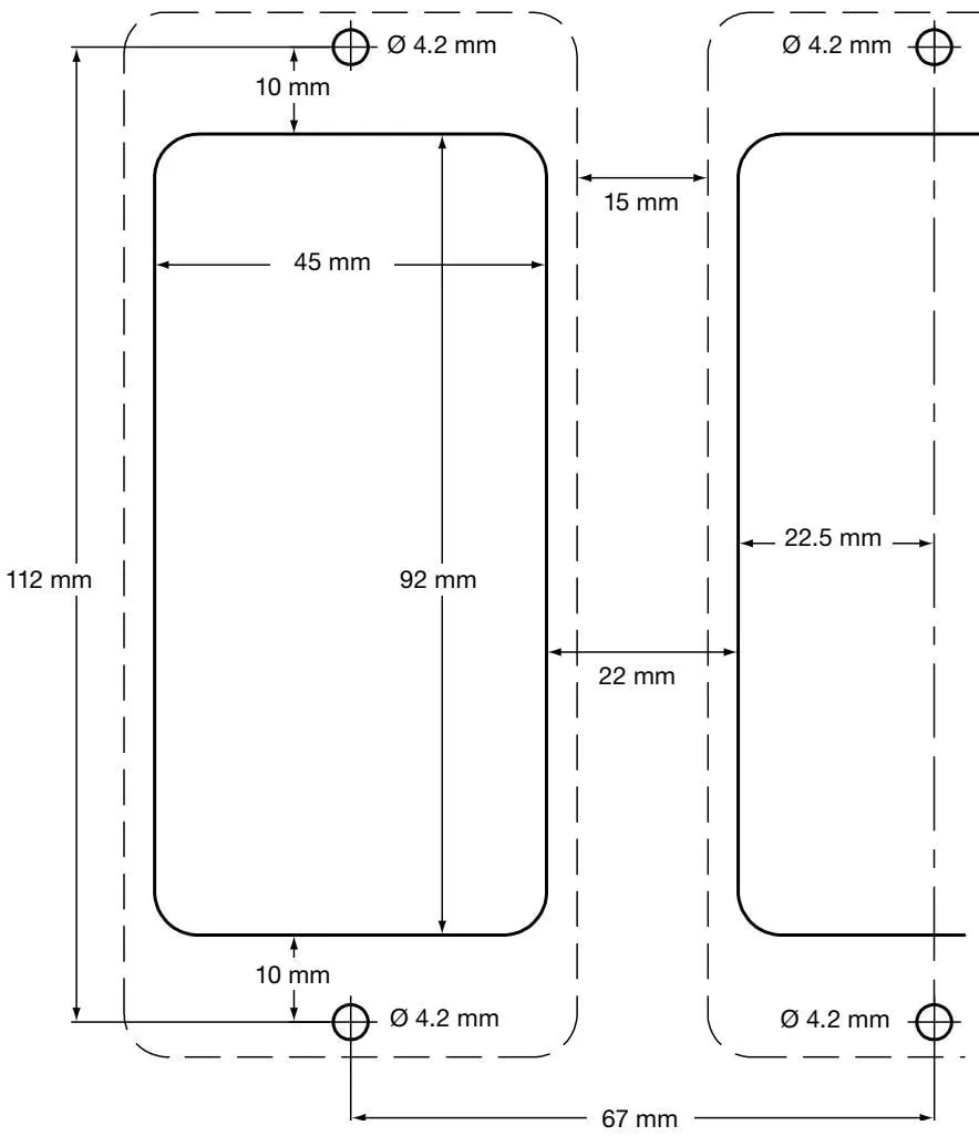
Figure 2 Baseplate/panel - cutout diagram
Fixing plate cutout notes:
- Solid lines indicate the cutout required for the installation panel.
- Dashed lines indicate the product outline
- The minimum clearance required between products is 15 mm, to facilitate product heat dissipation and cooling.
- For panel and wall mounting, the mounting hole dimensions are the same.
5. Electrical Installation
Note: Before installing this product, please read the safety information in Section 1.

Warning: Before touching the wiring terminals, disconnect the power supply as there may be contact with hazardous voltage.
Use only the connectors provided with the product, or spare parts. Using other different connectors must comply with product safety and authorization.
5.1 General Wiring Instructions
The product has been designed with user safety in mind, but the following points must be noted:
Maintenance personnel must be qualified to operate under hazardous voltage.
Ensure correct installation. Failure to follow these rules may result in a reduced safety level of the product.
The product design relies on building installation overcurrent protection and main isolation.
All phase conductors must be fitted with 3-amp current-limiting protection devices. If current-limiting protection devices are installed on both power lines, the operation of one device must trigger the other. Please refer to IEC60364 (Building electrical installations), or follow local regulations for overcurrent protection requirements.
Relay circuits must be fitted with 3 A fast-blow fuses.
Relay contacts must use the same phase as the main power supply.
Designed according to installation category II.
Wiring standards:
- IEC60364 - Low-voltage electrical installations
- EN50156 - Electrical equipment for furnaces and ancillary equipment
- BS6739 - Instruments for process control: installation design, practice, or corresponding local standards.
- National and local electrical codes (NEC) or Canadian Electrical Code (CEC) for the United States and Canada. Note: Use NEC Class 1, with temperature rating greater than 75 °C. If cables are exposed to higher temperatures, select a higher temperature rating.
The shield of signal cables must be connected to ensure electromagnetic compatibility.
All external circuits must meet and maintain IEC 60364 or equivalent double protection requirements.
Additional measures must be taken to prevent accessible components (such as signal terminals) from coming into contact with power lines, preventing power terminals from suddenly becoming loose. Additional devices should be as close to the circuit board as possible, but no additional force should act on the wiring terminals. For example, use cable ties to bundle live and neutral wires together. If one becomes loose, the other will prevent it from contacting other components.
A disconnecting device (switch or circuit breaker) must be provided in the building system, and this product must:
- Have sufficient breaking capacity;
- Be as close to the equipment as possible for easy operator access;
- Not be installed in a difficult-to-operate location;
- Be able to disconnect all phase conductor terminals;
- Be labeled as the product’s disconnecting device;
- Not affect protective grounding;
- Not be used as the main power supply;
- Comply with IEC60947-1 and IEC60947-3 disconnecting device requirements;
- See Section 10 ‘Technical Information’ for terminal and cable specifications.
5.2 Main Wiring
- Please read Section 5.1 - General Wiring Instructions before connecting the main power supply;
- All live conductor terminals must be fitted with fuses;
Disconnecting devices comply with IEC 60947-1 and IEC 60947-3
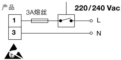
Disconnecting devices comply with IEC 60947-1 and IEC 60947-3
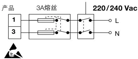
Figure 3 220/240 Vac power supply Disconnecting devices comply with IEC 60947-1 and IEC 60947-3
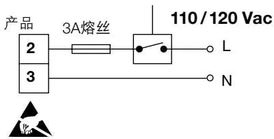
Disconnecting devices comply with IEC 60947-1 and IEC 60947-3
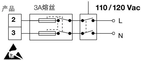
Figure 4 110/120 Vac power supply
- Double or reinforced isolation must be used between the following devices:
- Live conductor terminals (main power and relay outputs)
- Other low-voltage devices (other components/terminals/wires)
- The relays and switching devices shown on the wiring diagram are in the de-energized position;
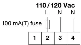
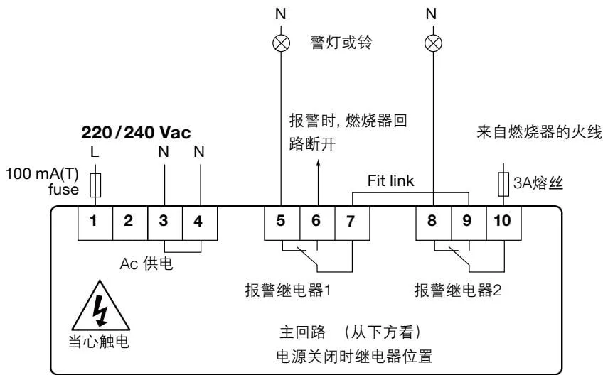

220 / 240 Vac main power input - live T1 - neutral T3 or T4
110 / 120 Vac main power input - live T2 - neutral T3 or T4
Figure 5 Select operating voltage
5.3 Signal Wiring Instructions
The maximum cable length for all transmitters is 50 meters.
LP30 and LP31 UL Sensors Only
LP30 and LP31UL sensors provide four-core 18 AWG, 12-inch long colored pigtail leads. Cut to the required length and connect to a suitable metal junction box. Metal flexible conduit is required between the sensor and the terminal box to provide environmental protection and facilitate electrical wiring. A 1/2” NPT adapter cable gland is provided. See the L30 and LP31 installation and maintenance guides for details.
5.4 Signal Wiring
If signal cables or shields are grounded at both ends, loop currents will be generated due to unequal ground potentials (voltages) at both ends. If the wiring diagram is correctly followed, the sensor should be grounded at one end.
Product grounding is functional grounding, not protective grounding.
Protective grounding prevents electric shock in the event of a single fault. Functional grounding ensures normal operation of the product. In this product’s application, functional grounding serves as a source or discharge pool for electromagnetic interference. The ground terminal must follow EMC directive grounding.
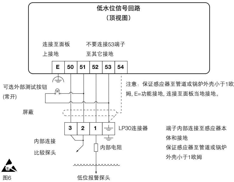
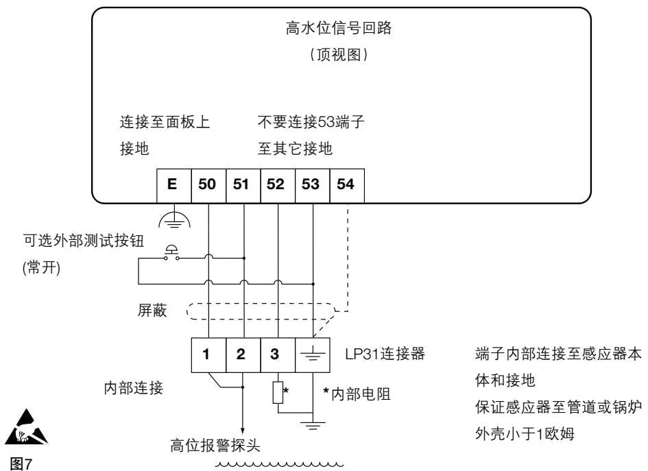
Note: Ensure that the sensor to pipe or boiler shell is less than 1 ohm. E = functional ground, connected to panel local ground.
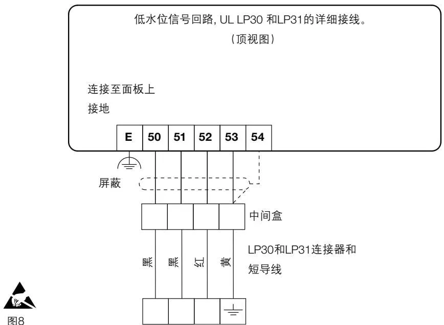
Figure 8 Low water level signal circuit, detailed wiring of UL LP30 and LP31 (top view)
6. Commissioning
6.1 Overview
At normal water level, the green LED is displayed, and the boiler panel is at normal water level. If the green LED goes out every few seconds, it indicates that automatic cyclic detection is in progress.
To perform a manual test:
- At normal water level, press and hold the AL button until the green (normal) LED goes out and the red (alarm) LED lights up (approximately 5-6 seconds). The boiler control panel should display an alarm signal.
- Release the test button; after a short delay, the green LED and red LED will go out, indicating that the internal detection circuit has been verified. The boiler panel indication returns to normal status.
If the boiler control panel has an external circuit latch, the control panel must be restarted.
- If an optional external test switch is connected, press and hold until the same test sequence appears (approximately 5-6 seconds).
- Lower the boiler water level below the low alarm level, or raise it above the high alarm level. The green LED goes out, the red LED lights up, and the boiler panel indicates an alarm.
- After the water level alarm returns to normal, the control relay will be energized, allowing the burner to ignite (after resetting the latch).
See separate documentation for detailed Spirax Sarco test guidance.

Figure 9. Buttons and definitions
Press and hold the button to test the alarm. Provides complete testing of the sensor, controller, and related circuits. Other buttons have no function.
7. Communication
7.1 Infrared (IR)
Adjacent products within a certain range can communicate via infrared bus.
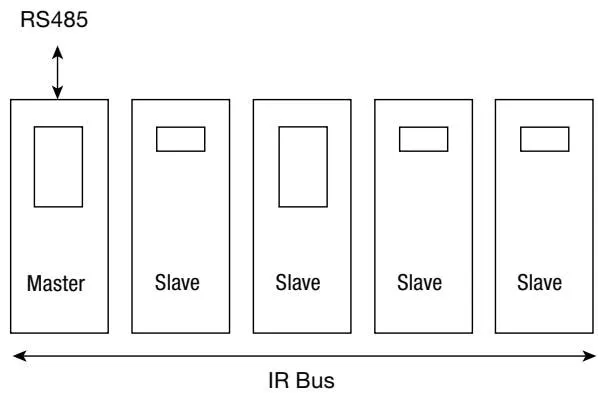
It can transmit parameters of up to 7 slave products to a master product installed with RS485 (as shown in the figure). The LC3050 is set as a slave.
The product connected to the RS485 network must be installed to the left of all infrared bus slaves (Figure 10), and select ‘OUTPUT-COMMS’ menu in ‘MASTER’.
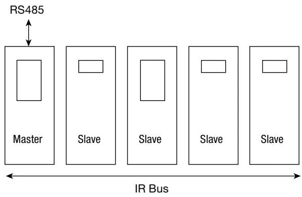
Figure 10
Two or more infrared buses can share the same chassis or DIN rail. Bus 2 will ignore bus 1. See Figure 11.
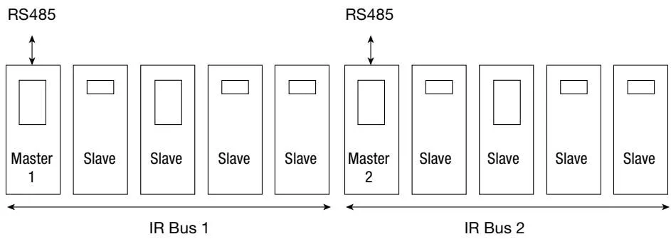
Figure 11
If a slave is to be added to an existing infrared bus, re-select ‘MASTER’.
Only one infrared master can transmit parameters to the RS485 network. If a slave is connected to the RS485 network, then only it can transmit parameters to the RS485 network.
Warning: Do not cover or obstruct the infrared light between products.
7.2 RS485 Address
An offset is added to each device’s register address (see above), depending on its position on the infrared bus, that is, the master offset is 0, the first device to the right of the master has offset 100, the next device to the right has offset 200, and so on.
| Infrared address | 1 | 2 | 3 | 4 | 5 |
|---|---|---|---|---|---|
| 485 offset | 0 | 100 | 200 | 300 | 400 |
Figure 12
8. Maintenance
Note: Before performing any maintenance, please read Section 1 Safety Information.
8.1 Cleaning Instructions
Use a cloth dampened with deionized water or isopropyl alcohol. Using other cleaning materials may damage the product and void the warranty.
The product requires no special servicing, preventive maintenance, or inspection.
However, boiler water level control and level alarms require testing and inspection. Health and Safety Executive guidance PM5 provides general guidance.
LP30
Inspect and clean the LP30 annually, especially the threaded contact surfaces between the probe and electrode.
If boiler water quality causes accumulation of insulating fouling or oxides, regular cleaning is recommended.
9. Fault Diagnosis
Faults are most likely to occur during installation and commissioning. The most common fault is incorrect wiring. If the product displays a fault message after power-up, the cause of the fault must be found. To simplify and assist this process, the product has a test menu.
Warning:
Before starting fault diagnosis, please read Section 1 Safety Information and Section 5.1 Wiring Instructions.
Please note that there is hazardous voltage; only qualified personnel may perform fault diagnosis.
Before opening the enclosure cover, the product must be disconnected from the power supply and must be properly installed before powering up.
Failure to follow the procedures in this manual for fault diagnosis will result in a reduced safety level.
| Symptom | Action |
|---|---|
| 1 Screen does not display | 1. Turn off the product power. 2. Check that all wiring is correct. 3. Check that the external fuse is normal, replace if necessary. 4. Check that the power supply voltage is within the specified range. 5. Turn on the power. If the symptom persists, return and replace the product. Consider the possibility that the product has been damaged by overvoltage. Consider installing an additional AC line protection device between the product and the power supply. Position the protection device as close to the product as possible for adequate protection. |
| 2 Red LED continuously on (LP30 low level alarm) | 1. Sensor cable to ‘low alarm tip’ connection is open circuit 2. Comparison probe shorted to ground 3. Ground circuit open 4. Sensor wiring reversed 5. Low alarm probe shorted with comparison probe |
| 3 Red LED continuously on (LP31 high level alarm) | 1. Sensor cable to ‘high alarm tip’ connection is open circuit 2. Comparison probe and sensor terminal 3 open circuit 3. Ground circuit open 4. Sensor wiring reversed |
| 4 Red and green LEDs continuously on (LP30 low level alarm) | 1. Sensor cable to ‘low alarm tip’ shorted to ground 2. Sensor wiring reversed 3. Comparison probe open circuit |
| 5 Red LED continuously on (LP31 high level alarm) | 1. Sensor cable to ‘high alarm tip’ connection is open circuit (sensor terminal 1 or 2) 2. Sensor wiring reversed |
| 6 At startup, green LED flashes rapidly, then red LED lights for 12 seconds, then green LED flashes for 4 seconds | 1. No fault exists - the controller safety self-test simulates a fault, but is working normally |
| 7 High/low water level alarm occurs | 1. Immediately check the actual boiler water level. If the water level is in the alarm zone, take measures to restore the water level. 2. If an alarm occurs and the water level is normal, immediately shut down the boiler and check for faults |
| 8 Controller internal fuse blown | 1. Check whether the power supply is below 264 Vac or 132 Vac, and the ambient temperature inside the control panel is less than 55 °C. If either limit is exceeded, the controller internal fuse may have blown, and the controller needs to be replaced. 2. Ensure that between sensor power supply terminals 52 and 53, or between terminal 1 and sensor ground, approximately 2-2.5 Vac |
10. Technical Information
10.1 Technical Assistance
Contact your local Spirax Sarco representative.
10.2 Returning Faulty Equipment
Please return all parts of the product to your local Spirax Sarco representative. Please ensure all parts are well packaged for transport (preferably using the original carton).
Please provide the following information when returning equipment:
- Your name, company name, address and telephone number, order number and invoice, and return delivery address.
- Equipment description and serial number.
- Detailed description of the fault or repair required.
- If the equipment is returned within the warranty period, please indicate:
- Date of purchase.
- Original order number.
10.3 Power Supply
| Supply voltage range | 220/240 VA (198 V to 264 V) | | | 110/120 VA (99 V to 132 V) | | Frequency | 50 - 60 Hz | | Power consumption | 230 V/30 mA, or 115 V/60 mA |
10.4 Environment
| General | Indoor use | | Maximum altitude | 2000 m above sea level | | Ambient temperature range | 0 - 55 °C (32 - 131 °F) | | Maximum relative humidity | 80% at 31 °C (88 °F) linearly decreasing to 50% at 40 °C (104 °F) | | Overvoltage | III | | Pollution degree | 2 (as supplied) 3 (when installed in an enclosure) - minimum IP54 or UL50 / NEMA Type 3, 3S, 4, 4S, 6, 6P or 13. See Section 4, Mechanical Installation | | Sealing rating (front panel only) | NEMA Type 4 hose down only (UL certified) approved and compliant with IP65 (TRAC GLOBAL certified) | | Panel screw torque | 1 - 1.2 Nm | | LVD (Safety) | Electrical safety EN 61010-1 UL61010-1 CAN/CSA C22.2 No. 61010-1 | | EMC | Suitable for heavy industrial locations | | Housing color | Light gray (similar to RAL7035) | | Housing material | ABS polycarbonate | | Front panel color | Pantone 294 (blue) | | Front panel material | Silicone rubber, 60 shore | | Solder | Tin/lead (60/40%) |
10.5 Cables/Data Lines and Connectors
Power and Signal Connectors
| Terminal | Plug-in terminal block with screw connector | | Cable size | 0.2 mm² (24 AWG) to 2.5 mm² (14 AWG) | | Stripping length | 5 - 6 mm |
Note: (Use only connectors provided by Spirax Sarco - otherwise the safety level will be reduced)
Sensor Cables/Wires
| Type | High temperature | | Shield type | Shielded | | Number of cores | 4 cores | | Cable size | 1 - 1.5 mm² (18 - 16 AWG) | | Maximum length | 50 m (328 ft) | | Recommended | Prysmian (Pirelli) FP200, Delta Crompton Firetuf OHLS |
10.6 Input Technical Data
Level Sensor
| Minimum conductivity | 30 μS/cm or 30 ppm |
10.7 Output Technical Data
Relay(s)
| Contacts | 2 × single-pole changeover relays (SPCO) | | Rated voltage (maximum) | 250 Vac | | Resistive load | 3 amp at 250 Vac | | Inductive load | 1 amp at 250 Vac | | AC motor load | 1/4 HP (2.9 amp) at 250 Vac 1/10 HP (3 amp) at 120 Vac | | Pilot duty | C300 (2.5 amp) - control circuit/coil | | Electrical life (operations) | 3 x 10⁵ or greater, depending on load | | Mechanical life (operations) | 30 x 10⁶ |
Infrared Communication
| Physical layer | IrDA | | Baud rate | 38400 | | Range | 10 cm | | Working angle | 15° | | Eye safety information | Summary: EN 60825-12:2007 Safety of laser products - does not exceed Class 1 emission limit (AEL) |
11. Appendix
Parameter and Register Data
| Register | Parameter |
|---|---|
| 0 | 6 (address) |
| 1 | Pump + alarm status |
| 2 | - |
| 3 | - |
| 4 | - |
| 5 | - |
| 6 | - |
| 7 | - |
| 8 | - |
| 9 | - |
The register format is a 16-bit integer, with the high 8 bits transmitted first.