

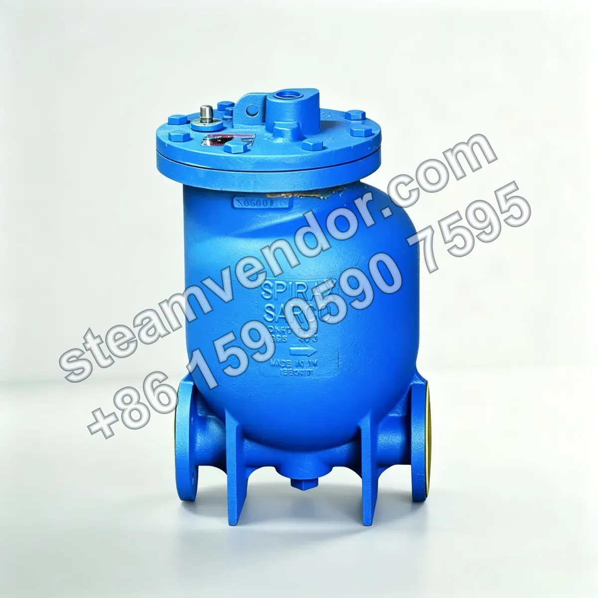
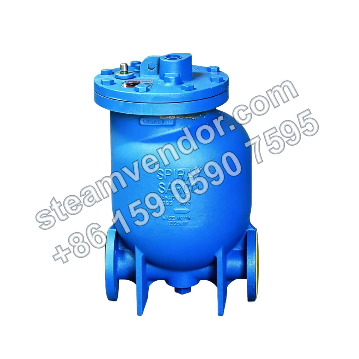
The Spirax Sarco MFP14/MFP14S/MFP14SS is an automatic condensate recovery pump powered by steam or compressed air. The series is available with ductile iron, cast steel, or stainless steel pump bodies, with a maximum allowable pressure of 16 bar g and a maximum allowable temperature of 300°C. It is designed for discharging and lifting condensate from temperature-controlled heat exchangers, vacuum equipment, and pressurized equipment, enabling reliable liquid lifting and recovery under insufficient differential pressure or vacuum conditions.
MFP14 DN50 Condensate Recovery Automatic Pump | Spirax Sarco
1 / 2
MFP14/MFP14S/MFP14SS Automatic Condensate Recovery Pump | Spirax Sarco
An automatic condensate recovery pump powered by steam or compressed air for condensate discharge and lifting under low differential pressure and vacuum conditions.
Select model
Genuine product assurance
We can help verify product data and purchasing details.
Model confirmation
Confirm model, connection and key options before ordering.
After-sales support
After-sales communication support is provided according to the order agreement.
Specifications
- Motive Medium
- Steam or compressed air
- Maximum Motive Gas Inlet Pressure
- MFP14/MFP14S: 13.8 bar g; MFP14SS: 10.96 bar g
- Maximum Allowable Pressure
- MFP14/MFP14S: 16 bar g @ 120°C; MFP14SS: 16 bar g @ 93°C
- Maximum Allowable Temperature
- MFP14: 300°C @ 12.8 bar g; MFP14S: 300°C @ 10.8 bar g; MFP14SS: 300°C @ 9.3 bar g
- Maximum Operating Pressure
- MFP14/MFP14S: 13.8 bar g @ 198°C; MFP14SS: 10.96 bar g @ 188°C
- Maximum Operating Temperature
- MFP14/MFP14S: 198°C @ 13.8 bar g; MFP14SS: 188°C @ 10.96 bar g
- Pump Body Material
- Ductile iron (MFP14), cast steel (MFP14S), stainless steel (MFP14SS)
- Wetted Parts Material
- Stainless steel (float, linkage, valve plug and seat)
- Connection Size
- MFP14: 1"-3" threaded / DN25-DN80 × DN50 flanged; MFP14S/MFP14SS: DN50 flanged
- Flange Standard
- EN 1092 PN16, ANSI B 16.5 Class 150, JIS/KS B 2238 10
- Seal Material
- EPDM
- Displacement per Cycle
- DN25/DN40: 7 L; DN50: 12.8 L; DN80 × DN50: 19.3 L
- Steam Consumption
- ≤20 kg/h (DN50/DN80 × DN50); ≤16 kg/h (DN25/DN40)
- Air Consumption
- ≤5.6 dm³/s (DN50/DN80 × DN50); ≤4.4 dm³/s (DN25/DN40)
- Standard Pumped Liquid Specific Gravity
- 1 to 0.8
- Recommended Inlet Head
- 0.3 m
- Minimum Inlet Head
- 0.15 m
- Ambient Temperature Range
- -10°C to 200°C
- Certifications
- PED 97/23/EC, ATEX 94/9/EC, EN 10204 3.1
Application scenarios
Condensate Discharge and Lifting from Temperature-Controlled Heat Exchangers
Used with a float-operated steam trap to remove condensate from temperature-controlled heat exchangers. Steam or compressed air is used as the motive medium to discharge and lift condensate when the differential pressure is insufficient or under vacuum conditions.
Condensate Discharge and Lifting from Vacuum Equipment
Used to discharge condensate and other liquids from equipment operating under vacuum and lift them to a downstream discharge or recovery point. Under suitable operating conditions, this series can drain directly from vacuum equipment.
Condensate Lifting and Recovery from Pressurized Equipment
Used to discharge condensate and other liquids from pressurized equipment and lift them to recovery or discharge pipework at a higher level. Under suitable operating conditions, this series can drain directly from pressurized equipment.
Selection points
Pump Body Material Varies by Model
The MFP14 has a ductile iron pump body, the MFP14S has a cast steel pump body, and the MFP14SS has a stainless steel pump body.
Connection Size and Type Vary by Model
The MFP14 is available with 1-inch to 3-inch threaded connections and various DN flanged connection sizes. The MFP14S and MFP14SS use DN50 flanged connections.
Stainless Steel Wetted Parts
Wetted parts including the float, linkage, valve plug and seat are made of stainless steel.
EPDM Seals
The seals used in this product series are made of EPDM.
ATEX Directive Compliance
This product series complies with the ATEX 94/9/EC directive.
Installation & maintenance notes
Maintain the Specified Inlet Head
Provide a stable inlet head during installation. The recommended value is 0.3 m, and it must not be less than 0.15 m, to prevent reduced pumping capacity or equipment flooding caused by insufficient inlet flow.
Isolate, Depressurize and Cool Before Maintenance
Before disassembly or maintenance, isolate the motive medium and condensate pipework. Confirm that the pump body and associated pipe sections have been fully depressurized and cooled to a safe temperature before starting work.
FAQ
How does the MFP14 series automatic pump operate?
The MFP14 series automatic pump uses steam or compressed air as the motive source. A float mechanism opens the discharge path when the pumped medium reaches the set level, allowing condensate to be lifted to a higher point and, under certain operating conditions, discharged directly into the recovery line.
What are the key considerations when selecting this pump?
Select the appropriate connection size and model (MFP14, MFP14S or MFP14SS) based on the motive medium pressure, system backpressure, inlet head and required displacement. Refer to the selection charts and apply the inlet-head correction factor to confirm the final displacement.
How do the applications differ for the various connection sizes?
Different connection sizes correspond to different flanged or threaded connections and inlet and outlet dimensions. Selection should be based on the actual drainage flow rate and system pressure, with combinations such as DN25, DN40 and DN50 chosen to meet the total effective head and displacement requirements.
Are additional certificates or certifications required for use?
If certificates are required, specify this when placing the order. The product complies with the applicable directives, and an EN 10204 3.1 certificate can be provided. The design complies with the applicable standards and regulations. Specific certificate requirements are subject to the actual order details.
What should be considered during installation and maintenance?
Refer to the installation and maintenance guide supplied with the product. During installation, ensure that steam or gas entering the condensate pump has been vented or condensed. A monitor can optionally be fitted to the top of the pump cover, and frost-protection and insulation accessories can be used where necessary to improve safety and energy efficiency.