
Installation and Maintenance Guide
1. Safety Information
The correct installation, commissioning and maintenance of this product by qualified personnel in accordance with the operating instructions is the only guarantee of safe operation (see Section 1.11). After installation, the installation and safety instructions for the piping system and plant buildings must be observed. Personnel must be familiar with the correct use of tools and provided with the necessary safety equipment.
1.1 Intended Use
Refer to the Installation and Maintenance Guide, nameplate and technical documentation to ensure that the product is suitable for its intended use. Ensure that the product is suitable for the application shown in the table below.
| Product | Group 2 gases | Group 2 liquids |
|---|---|---|
| MFP14 single-, twin- or triple-pump package - DN25 | 2 | SEP |
| MFP14 single-, twin- or triple-pump package - DN40 | 2 | SEP |
| MFP14 single-, twin- or triple-pump package - DN50 | 2 | SEP |
| MFP14 single-, twin- or triple-pump package - DN80 x DN50 | 2 | SEP |
I) The product is designed for use with Group 2 fluids under the Pressure Equipment Directive, including steam, air and water/condensate. For use with other fluids, consult Spirax Sarco. II) Ensure that the materials used in the product are suitable for the operating conditions and that the maximum and minimum system pressure and temperature are within the product’s design range. If the product’s maximum operating range is lower than the system operating conditions, or if product failure could result in overpressure or overtemperature, install a safety device to protect against such hazards. III) Ensure that the product is installed correctly and that the inlet and outlet are not reversed. IV) Spirax Sarco products cannot withstand external pressure. Installers must ensure that external forces from the system do not act on this product. V) Before installing the product in a steam or other high-temperature system, remove the protective covers from all product connections and the protective film from the nameplate.
1.2 Accessibility
After installation, ensure that there is sufficient space for operation. Where necessary, prepare a safe working platform before operating the product. Provide lifting equipment where necessary.
1.3 Lighting
Ensure that adequate lighting is available, particularly when carrying out detailed or complex work.
1.4 Hazardous Fluids or Gases in the Pipeline
Consider in advance which fluids are, or may be, present in the pipeline. Be aware of flammable materials, substances hazardous to health, and hot or cold materials.
1.5 Hazardous Working Environment
Consider the risks of explosion, oxygen deficiency, such as inside tanks or in low-lying areas, hazardous gases, hot or cold temperatures, hot surfaces, fire hazards, such as during welding, excessive noise and moving machinery.
1.6 The System
Understand the operation of the complete system. Before carrying out any operation, such as closing an isolation valve or switching off an electrical supply, consider whether this could place any other part of the system or any personnel at risk.
Hazards may include isolating vents or protective devices and disabling controls or alarms. Open and close isolation valves slowly to prevent system shock.
1.7 Pressure Systems
Ensure that pressure is isolated or fully vented from the system. Consider double isolation by installing two isolation valves, locking or tagging closed valves. Do not assume that a pressure gauge reading of zero means that the system has been fully depressurized.
1.8 Temperature
After isolating the product, allow it to cool to room temperature to avoid burns.
1.9 Tools and Spares
Before starting work, ensure that suitable tools and spare parts are available. Use genuine Spirax Sarco spare parts only.
1.10 Protective Clothing
Consider whether operators or nearby personnel require protective clothing to protect against hazards such as chemicals, hot or cold temperatures, radiation, noise, falling objects, and eye or facial injuries.
1.11 Permits to Work
All work must be carried out by competent personnel or under their supervision. Installation and operating personnel must be trained in accordance with the product’s Installation and Maintenance Guide so that they can use the product correctly.
Where a permit-to-work system is in operation, personnel must comply with the system. Where such a system is not in operation, the person responsible should be aware of the nature of the work and, where necessary, have a safety assistant.
Where necessary, post warning notices.
1.12 Handling
Manual handling of large or heavy products may cause injury. Lifting, pushing, pulling, carrying or supporting heavy loads with the body can cause injury, particularly back injuries. It is recommended that the workload, individual capabilities, load and working environment be assessed, and that suitable handling methods be adopted according to site conditions.
1.13 Residual Heat
During normal use, the external surface of this product may become very hot. When operated at the maximum permitted operating temperature, the product surface temperature may reach 200°C (392°F).
This product is not self-draining. Care must be taken when removing or moving the product from its installation position (refer to the Maintenance Instructions).
1.14 Freezing
For non-self-draining products used in ambient temperatures below freezing point, protection against frost must be provided.
1.15 Disposal
Unless otherwise stated in the Installation and Maintenance Guide, this product is recyclable and can be disposed of without ecological hazard, provided that it is disposed of correctly.
1.16 Returning Products
In accordance with EC health, safety and environmental laws, when products are returned, customers and resellers must provide hazard information and take care when handling any residual contamination or mechanical damage that could present a health, safety or environmental hazard. Hazard information must be provided in writing, including health and safety data sheets stating any identified or potential hazards.
2. Product Information
2.1 Overview
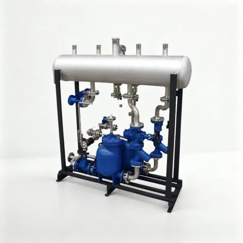
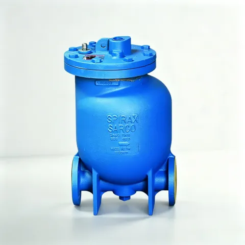
The Spirax Sarco MFP14 condensate recovery pump package, available as a single-, twin- or triple-pump package, is a condensate recovery unit consisting of an MFP14 automatic pump, an open tank and other necessary accessories mounted on a rigid frame. The unit is mainly used for pumping and recovering high-temperature condensate or other fluids. Packages incorporating MFP14S/SS pumps are also available. Please consult Spirax Sarco for details.
Options
MFP14 pump packages can be supplied with PSHE.
Complete insulation jackets are also available.
2.2 Dimensions and Pipe Connections
Single Pump Set
| Pump Set Model | Connection Type | AA Condensate Inlet | BB Condensate Inlet | CC Exhaust Steam Outlet | DD Overflow Outlet | FF Blowdown Outlet | GG Condensate Outlet | HH Motive Steam (Air) Inlet | UU Cooling Water Inlet | VV Cooling Water Outlet | WW Vent Outlet | XX MFP14 Blowdown Outlet |
|---|---|---|---|---|---|---|---|---|---|---|---|---|
| DN25 (1”) | PN16 | DN80 | DN80 | DN100 | DN80 | 1” (BSP) | DN25 | 1/2” (BSP) | DN25 | DN25 | DN100 | 1/2” (BSP) |
| DN25 (1”) | ANSI 150 | 3” | 3” | 4” | 3” | 1” (NPT) | 1” | 1/2” (NPT) | 1” | 1” | 4” | 1/2” (NPT) |
| DN40 (1 1/2”) | PN16 | DN80 | DN80 | DN100 | DN80 | 1” (BSP) | DN40 | 1/2” (BSP) | DN25 | DN25 | DN100 | 1/2” (BSP) |
| DN40 (1 1/2”) | ANSI 150 | 3” | 3” | 4” | 3” | 1” (NPT) | 1 1/2” | 1/2” (NPT) | 1” | 1” | 4” | 1/2” (NPT) |
| DN50 (2”) | PN16 | DN80 | DN80 | DN150 | DN80 | 1” (BSP) | DN50 | 1/2” (BSP) | DN25 | DN25 | DN100 | 1/2” (BSP) |
| DN50 (2”) | ANSI 150 | 3” | 3” | 6” | 3” | 1” (NPT) | 2” | 1/2” (NPT) | 1” | 1” | 4” | 1/2” (NPT) |
| DN80 x DN50 (3” x 2”) | PN16 | DN80 | DN80 | DN150 | DN80 | 1” (BSP) | DN50 | 1/2” (BSP) | DN25 | DN25 | DN100 | 1/2” (BSP) |
| DN80 x DN50 (3” x 2”) | ANSI 150 | 3” | 3” | 6” | 3” | 1” (NPT) | 2” | 1/2” (NPT) | 1” | 1” | 4” | 1/2” (NPT) |
Dimensions mm (approximate)
| Pump Set Model | A | B | C | D | E | F | G | H | I | J | K | L | ∅M | N | T | X | A’ | X’ |
|---|---|---|---|---|---|---|---|---|---|---|---|---|---|---|---|---|---|---|
| DN25 (1”) | 1472 | 460 | 1130 | 1277 | 95 | 1300 | 1030 | 1759 | 250 | 356 | 133 | 260 | 250 | 410 | 860 | 609 | 1960 | 613 |
| DN40 (1 1/2”) | 1472 | 460 | 1130 | 1277 | 95 | 1300 | 1030 | 1759 | 250 | 356 | 145 | 260 | 250 | 410 | 880 | 609 | 1960 | 613 |
| DN50 (2”) | 1472 | 460 | 1130 | 1277 | 95 | 1300 | 1030 | 1759 | 250 | 356 | 159 | 260 | 250 | 410 | 978 | 609 | 2202 | 613 |
| DN80 x DN50 (3” x 2”) | 1472 | 569 | 1130 | 1277 | 95 | 1300 | 1030 | 1759 | 250 | 391 | 159 | 200 | 250 | 519 | 978 | 661 | 2202 | - |
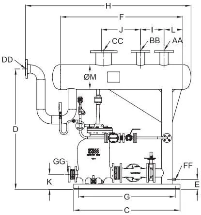
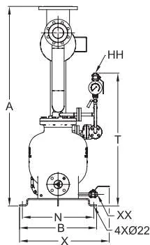
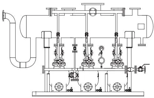
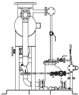
MFP14 DN25, DN40, DN50, DN80 Single Pump Sets
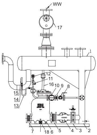

MFP14 DN25, DN40, DN50, DN80 Single Pump Sets with Optional Flash Steam Recovery Unit
Net Weight kg (approximate)
| Model | DN25 (1”) | DN40 (1 1/2”) | DN50 (2”) | DN80 x DN50 (3” x 2”) |
|---|---|---|---|---|
| Pump Set | 270 | 270 | 300 | 330 |
| Pump Set with Flash Steam Recovery | 340 | 340 | 370 | 400 |
Twin Pump Set
| Pump Set Model | Connection Type | AA Condensate Inlet | BB Condensate Inlet | CC Exhaust Steam Outlet | DD Overflow Outlet | EE Drain Outlet | FF Blowdown Outlet | GG Condensate Outlet | HH Motive Steam (Air) Inlet | UU Cooling Water Inlet | VV Cooling Water Outlet | WW Vent Outlet | XX MFP14 Blowdown Outlet | YY MFP14 Blowdown Outlet |
|---|---|---|---|---|---|---|---|---|---|---|---|---|---|---|
| DN50 (2”) | PN16 | DN80 | DN80 | DN200 | DN80 | 3” (BSP) | 2” (BSP) | DN50 | 1” (BSP) | DN50 | DN50 | DN150 | 1/2” (BSP) | 1/2” (BSP) |
| DN50 (2”) | ANSI 150 | 3” | 3” | 8” | 3” | 3” (NPT) | 2” (NPT) | 2” | 1” (NPT) | 2” | 2” | 6” | 1/2” (NPT) | 1/2” (NPT) |
| DN80 x DN50 (3” x 2”) | PN16 | DN80 | DN80 | DN200 | DN80 | 3” (BSP) | 2” (BSP) | DN50 | 1” (BSP) | DN50 | DN50 | DN150 | 1/2” (BSP) | 1/2” (BSP) |
| DN80 x DN50 (3” x 2”) | ANSI 150 | 3” | 3” | 8” | 3” | 3” (NPT) | 2” (NPT) | 2” | 1” (NPT) | 2” | 2” | 6” | 1/2” (NPT) | 1/2” (NPT) |
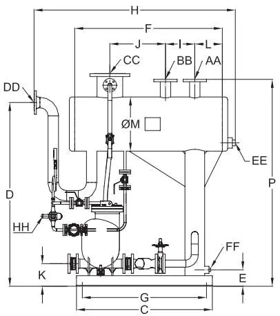
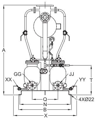
MFP14 DN50, DN80 Twin Pump Sets
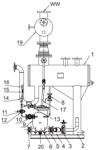
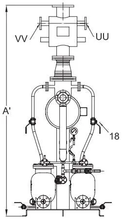
MFP14 DN50, DN80 Twin Pump Sets with Optional Flash Steam Recovery Unit
Dimensions mm (approximate)
| Pump Set Model | A | B | C | D | E | F | G | H | I | J | K | L | ∅M | N | P | Q | T | X | A’ |
|---|---|---|---|---|---|---|---|---|---|---|---|---|---|---|---|---|---|---|---|
| DN50 (2”) | 1812 | 1070 | 1160 | 1565 | 140 | 1260 | 1060 | 1718 | 250 | 475 | 193 | 235 | 450 | 1020 | 1762 | 520 | 596 | 1277 | 2788 |
| DN80 x DN50 (3” x 2”) | 1812 | 1070 | 1160 | 1565 | 140 | 1260 | 1060 | 1718 | 250 | 475 | 193 | 235 | 450 | 1020 | 1762 | 520 | 596 | 1277 | 2788 |
Net Weight kg (approximate)
| Model | DN50 (2”) | DN80 x DN50 (3” x 2”) |
|---|---|---|
| Pump Set | 600 | 640 |
| Pump Set with Flash Steam Recovery | 740 | 780 |
Triple Pump Set
| Pump Set Model | Connection Type | AA Condensate Inlet | BB Condensate Inlet | CC Exhaust Steam Outlet | DD Overflow Outlet | EE Drain Outlet | GG Condensate Outlet | HH Motive Steam (Air) Inlet | JJ Condensate Outlet | KK Condensate Outlet | MM Condensate Inlet | NN Condensate Inlet | UU Cooling Water Inlet | VV Cooling Water Outlet | WW Vent Outlet | XX MFP14 Blowdown Outlet | YY MFP14 Blowdown Outlet | ZZ MFP14 Blowdown Outlet |
|---|---|---|---|---|---|---|---|---|---|---|---|---|---|---|---|---|---|---|
| DN80 x DN50 (3” x 2”) | PN16 | DN100 | DN150 | DN300 | DN100 | DN40 | DN50 | DN40 | DN50 | DN50 | DN100 | DN150 | DN50 | DN50 | DN200 | 1/2” (BSP) | 1/2” (BSP) | 1/2” (BSP) |
| DN80 x DN50 (3” x 2”) | ANSI 150 | 4” | 6” | 12” | 4” | 1 1/2” | 2” | 1 1/2” | 2” | 2” | 4” | 6” | 2” | 2” | 8” | 1/2” (NPT) | 1/2” (NPT) | 1/2” (NPT) |
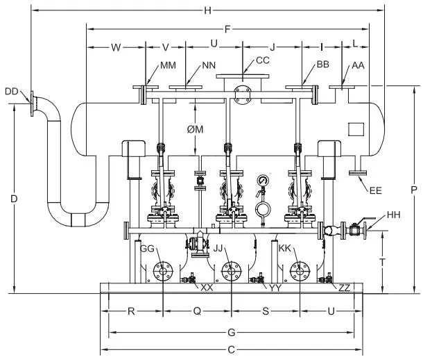
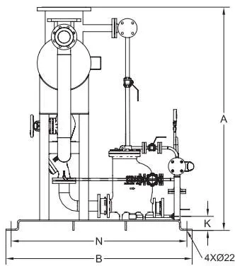
MFP14 DN80 Triple Pump Set
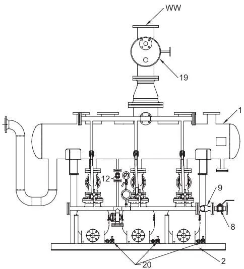
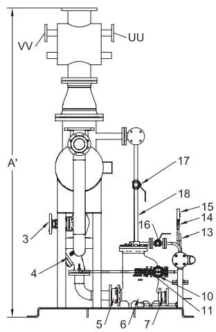
MFP14 DN80 Triple Pump Set with Optional Flash Steam Recovery Unit
Dimensions mm (approximate)
| Pump Set Model | A | B | C | D | F | G | H | I | J | K | L | ∅M | N | P | Q | R | S | U | T | V | W | A’ |
|---|---|---|---|---|---|---|---|---|---|---|---|---|---|---|---|---|---|---|---|---|---|---|
| DN80 x DN50 (3” x 2”) | 1918 | 1600 | 2300 | 1662 | 2480 | 1900 | 3102 | 350 | 520 | 194 | 240 | 450 | 1500 | 1818 | 600 | 550 | 600 | 520 | 550 | 350 | 500 | 2970 |
Net Weight kg (approximate)
| Model | DN80 x DN50 (3” x 2”) |
|---|---|
| Pump Set | 1300 |
| Pump Set with Flash Steam Recovery | 1460 |
2.3 Pressure-Temperature Curve
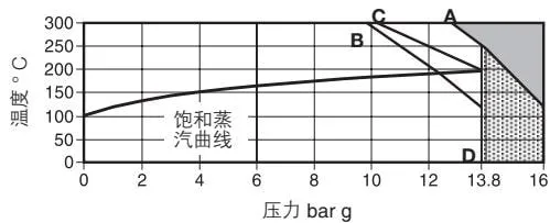
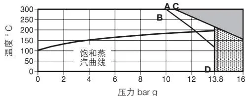
The operating conditions of the main component of the condensate recovery pump set, the MFP14 condensate pump, are shown in the figure and table below. For the other components, refer to the relevant technical information sheets (TIS).
Pressure/Temperature Limits
| Category | Model | Value |
|---|---|---|
| Valve body design conditions | PN16 | |
| Maximum motive gas inlet pressure (steam or other gas) | MFP14 and MFP14S | 13.8 bar g |
| Maximum motive gas inlet pressure (steam or other gas) | MFP14SS | 10.96 bar g |
| PMA maximum allowable pressure | MFP14 | 16 bar g @ 120°C |
| PMA maximum allowable pressure | MFP14S | 16 bar g @ 120°C |
| PMA maximum allowable pressure | MFP14SS | 16 bar g @ 93°C |
| TMA maximum allowable temperature | MFP14 | 300°C @ 12.8 bar g |
| TMA maximum allowable temperature | MFP14S | 300°C @ 10.8 bar g |
| TMA maximum allowable temperature | MFP14SS | 300°C @ 9.3 bar g |
| Minimum allowable temperature (contact Spirax Sarco for low-temperature applications) | 0°C | |
| PMO maximum operating pressure | MFP14 | 13.8 bar g @ 198°C |
| PMO maximum operating pressure | MFP14S | 13.8 bar g @ 198°C |
| PMO maximum operating pressure | MFP14SS | 10.96 bar g @ 188°C |
| TMO maximum operating temperature | MFP14 | 198°C @ 13.8 bar g |
| TMO maximum operating temperature | MFP14S | 198°C @ 13.8 bar g |
| TMO maximum operating temperature | MFP14SS | 188°C @ 10.96 bar g |
| Minimum operating temperature (contact Spirax Sarco for low-temperature applications) | 0°C |
MFP14
MFP14S
MFP14SS
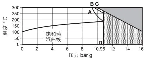

This product must not be used in this area.

For use in this area, contact Spirax Sarco. Standard products must not be used in this area.
A - D flange connection PN16 B - D flange connection JIS/KS 10 C - D flange connection ANSI 150
2.4 Components and Materials
Single-Pump Set
| No. | Component | Material |
|---|---|---|
| 1 | Condensate receiver | Carbon steel |
| 2 | Base and supports | Carbon steel |
| 3 | M10S2 ball valve (DN25 single-pump set) | Carbon steel |
| 3 | Butterfly valve (DN40, DN50, DN80 single-pump set) | Aluminium |
| 4 | FIG33 strainer | Cast iron |
| 5 | DCV10 check valve | Stainless steel |
| 6 | MFP14 mechanical pump | Ductile iron |
| 7 | DCV10 check valve | Stainless steel |
| 8 | M10S2 ball valve | Carbon steel |
| 9 | DCV3 check valve | Stainless steel |
| 10 | FT14 float and thermostatic steam trap | Ductile iron |
| 11 | FIG12 strainer | Ductile iron |
| 12 | M10S2 ball valve | Carbon steel |
| 13 | U-bend | Carbon steel |
| 14 | Cock | Copper |
| 15 | Pressure gauge | Carbon steel |
| 16 | Flexible metal hose | Stainless steel |
| 17 | PSHE heat exchanger (optional) | Carbon steel shell/stainless steel plates |
| 18 | M10S2 ball valve | Carbon steel |
Two-Pump Set
| No. | Component | Material |
|---|---|---|
| 1 | Condensate receiver | Carbon steel |
| 2 | Base and supports | Carbon steel |
| 3 | Butterfly valve | Aluminium |
| 4 | FIG33 strainer | Cast iron |
| 5 | DCV10 check valve | Stainless steel |
| 6 | MFP14 mechanical pump | Ductile iron |
| 7 | DCV10 check valve | Stainless steel |
| 8 | M10S2 ball valve | Carbon steel |
| 9 | DCV3 check valve | Stainless steel |
| 10 | FT14 float and thermostatic steam trap | Ductile iron |
| 11 | FIG12 strainer | Ductile iron |
| 12 | M10S2 ball valve | Carbon steel |
| 13 | M10S2 ball valve | Carbon steel |
| 14 | U-bend | Carbon steel |
| 15 | Cock | Copper |
| 16 | Pressure gauge | Carbon steel |
| 17 | Flexible metal hose | Stainless steel |
| 18 | M10S2 ball valve | Carbon steel |
| 19 | PSHE heat exchanger (optional) | Carbon steel shell/stainless steel plates |
| 20 | M10S2 ball valve | Carbon steel |
Three-Pump Set
| No. | Component | Material |
|---|---|---|
| 1 | Condensate receiver | Carbon steel |
| 2 | Base and supports | Carbon steel |
| 3 | Globe valve | Cast iron |
| 4 | FIG33 strainer | Cast iron |
| 5 | DCV10 check valve | Stainless steel |
| 6 | MFP14 mechanical pump | Ductile iron |
| 7 | DCV10 check valve | Stainless steel |
| 8 | M10S2 ball valve | Carbon steel |
| 9 | FIG33 strainer | Cast iron |
| 10 | FT14 float and thermostatic steam trap | Ductile iron |
| 11 | DCV3 check valve | Stainless steel |
| 12 | M10S2 ball valve | Carbon steel |
| 13 | U-bend | Carbon steel |
| 14 | Cock | Copper |
| 15 | Pressure gauge | Carbon steel |
| 16 | M10S2 ball valve | Carbon steel |
| 17 | M10S2 ball valve | Carbon steel |
| 18 | Flexible metal hose | Stainless steel |
| 19 | PSHE heat exchanger (optional) | Carbon steel shell/stainless steel plates |
| 20 | M10S2 ball valve | Carbon steel |
3. Installation
Note: Carefully read the safety information in Chapter 1 before installation.
Before installation, check the installation and maintenance instructions, nameplate and technical information to verify that this product is suitable.
3.1 Check the materials, pressure and temperature, including their maximum values, and confirm that the maximum operating limits of the product are not lower than the system operating conditions. The system must also include safety equipment to prevent overpressure.
3.2 Position the equipment correctly and arrange the flow direction correctly.
3.3 When installing the equipment on steam or other high-temperature fluid pipelines, remove the protective covers from the connections and the protective film from the nameplate.
3.4 After the pump set has been transported to the site, secure the complete pump set to the foundation using foundation bolts. (Note: Allow for the operating loads.)
3.5 Connect the condensate inlets of the pump set to the condensate drain piping of the site equipment. If there is only one condensate drain pipe, either condensate inlet may be used and the other inlet must be blanked off. If the site has more condensate drain pipes than the number of condensate inlets on the pump set, combine the pipes into a suitable number before connecting them to the pump set.
3.6 Connect the condensate outlet to the downstream recovery pipeline. If the recovery pipeline is long, it is recommended that a check valve be installed 5-6 metres from the pump discharge outlet to prevent water hammer caused by reverse condensate flow resulting from unsuitable condensate piping arrangements.
3.7 The HH connection is the motive medium inlet. The motive medium may be steam, compressed air or another medium. Check the maximum allowable pressure before connecting the medium. If the motive medium pressure is too high, installation of a pressure-reducing valve is recommended to reduce the motive medium pressure and improve equipment reliability. Install a suitable isolation valve upstream of the motive medium inlet to facilitate isolation of the motive medium supply. Note: The motive medium supply piping must be properly cleaned and blown through to prevent debris in the piping from damaging the motive medium inlet valve of the MFP14.
3.8 The CC connection is the equipment vent outlet and must be open to atmosphere. During normal operation, flash steam from the upstream condensate piping may be discharged through this outlet. If a large amount of steam is discharged, check whether the steam trap or bypass of the equipment connected to the condensate drain piping is leaking steam. When the operating pressure of the upstream equipment is relatively high, the amount of flash steam downstream of the steam trap will be greater, which may result in a larger amount of steam being discharged from the CC outlet. In this case, it is recommended that a flash vessel first be used to recover and utilise the low-pressure flash steam, and that the low-pressure condensate then be discharged to the condensate pump for recovery and reuse. This can effectively eliminate excessive venting and improve energy utilisation. The CC outlet may be connected to piping and discharged to the roof or outdoors, but the piping should not be excessively long and its diameter must not be reduced. Proper venting arrangements must also be provided for pump sets fitted with a flash steam recovery unit (PSHE).
3.9 The DD connection is the equipment overflow outlet. When the condensate flow exceeds the recovery capacity of the pump set, or when the pump or motive medium fails, condensate will overflow from the pump set through this outlet. If piping is to be connected, ensure that the maximum height of the downstream piping does not exceed the height of the DD outlet, and connect it to a safe discharge point.
4. Commissioning
After installing the equipment in accordance with Section 3, ensure that the CC vent outlet discharges directly to atmosphere. Open the valves on the condensate inlet piping and pump outlet piping. After the condensate slowly enters the collection tank, slowly open the isolation valve at the motive medium inlet to admit the motive medium into the pump body. The pump will then start operating.
When the pump is operating normally, a distinct venting sound can be heard at the end of each discharge cycle. A normal pump cycle generally takes more than 8 seconds. If the cycle time is less than this, check whether the condensate flow is too high and exceeds the pump capacity. If the condensate flow is within the pump capacity, remove the inlet and outlet check valves and check whether they are obstructed by debris.
Blow through the motive medium piping before admitting the motive medium to prevent debris in the piping from damaging the pump motive medium inlet valve.
5. Operation
The main operating component of this condensate recovery pump set is the MFP14 automatic pump. The MFP14 is a mechanical pump that uses steam, compressed air or another medium as the motive force and intermittently discharges the pumped medium, condensate, to the downstream pipeline based on the principle of positive displacement.
As long as the motive medium pressure is higher than the pressure in the pipeline downstream of the pump, condensate can be discharged through the pump. The capacity of the condensate recovery pump varies with changes in the motive medium pressure and the backpressure downstream of the pump. For detailed information, refer to technical information TI-P136-02.
If the pump is to be taken out of service for an extended period, drain the accumulated water from the pump set to prevent corrosion.
Note: After the pump set has been in service for 24 hours, hot-tighten all bolts and nuts to prevent local leakage caused by thermal expansion and contraction of the equipment.
6. Maintenance
Caution: Read the safety information in Chapter 1 carefully before carrying out maintenance.
Warning: The pump cover and valve cover gaskets contain thin stainless steel support rings. Improper handling may cause personal injury.
6.1 General Information
Before servicing, the isolation valve in the motive medium line must be closed and the pressure reduced to atmospheric pressure. Allow the pump to cool, and ensure that all contact surfaces are clean during reassembly.
As long as the safety procedures are followed, the pump assembly and some components can be serviced online. It is recommended that new gaskets and spare parts be fitted after each maintenance operation. Always use the correct tools and the necessary protective equipment. After maintenance is complete, open the isolation valve slowly and check for leakage.
Take care when dismantling the pump because of the powerful spring assembly, which may cause injury if it is released.
6.2 Component Servicing and Replacement
For details of servicing and replacement procedures for all components in the condensate recovery pump assembly, refer to the installation and maintenance instructions supplied with the respective components.
7. Troubleshooting
If a correctly selected MFP14 pump does not operate properly, check whether there is a problem with the installation. In an existing installation, intermittent pump operation is usually caused by variations in the system motive gas supply or backpressure exceeding the original design parameters. After identifying the conditions and fault shown below, check the following items one by one.
Caution: Installation and fault diagnosis must be carried out by qualified personnel. Before opening the pump or pipework, ensure that the internal pressure has been fully released and that the motive gas supply line is closed to prevent uncontrolled pump discharge. When fully dismantling the pump, loosen and remove the nuts/connecting pipes slowly. This makes it possible to determine whether pressure remains in the pipework before the fittings or components are completely removed. Pressure must be released before any connection is opened.
| Symptom/Cause | Details |
|---|---|
| Symptom 1 | Pump will not start |
| Cause 1a | Motive supply switched off |
| Diagnostic Check 1a | Open the valve to supply motive gas |
| Cause 1b | Condensate inlet pipe closed |
| Diagnostic Check 1b | Open all valves to allow condensate to reach the pump |
| Cause 1c | Condensate discharge pipe closed |
| Diagnostic Check 1c | Open all valves to allow condensate to discharge freely |
| Cause 1d | Motive pressure is insufficient to overcome backpressure |
| Diagnostic Check 1d | Check the motive pressure and static backpressure. Adjust the motive pressure to 0.6-1 bar or more above the static backpressure |
| Cause 1e | Check valve installed in the wrong direction |
| Diagnostic Check 1e | Check that the direction is correct and rectify it if necessary |
| Cause 1f | Vent obstructed |
| Diagnostic Check 1f | In an open or closed system, ensure that the vent pipe is connected to the pump or receiver without obstruction and is self-draining |
| Symptom/Cause | Details |
|---|---|
| Symptom 2 | Motive supply line or equipment floods, but the pump appears to operate normally (timed discharge can be heard) |
| Cause 2a | Pump undersized |
| Diagnostic Check 2a | Check the rated capacity in the capacity table. Increase the check valve size or install an additional pump as required |
| Cause 2b | Insufficient filling head |
| Diagnostic Check 2b | Refer to Part 1, Page 2 - lower the pump to provide the required filling head |
| Cause 2c | Motive gas is insufficient to achieve the rated capacity |
| Diagnostic Check 2c | During operation, check the set motive pressure and maximum backpressure. Compare them with the capacity table and increase the motive pressure as required for the necessary capacity |
| Cause 2d | Condensate inlet pipe obstructed |
| Diagnostic Check 2d | Use full-bore fittings. Clean the strainer, if fitted, and check that all valves are fully open |
| Cause 2e | Inlet or outlet check valve stuck open (debris) |
| Diagnostic Check 2e | Isolate the check valve and release the pipework pressure. Remove the check valve, inspect the valve disc and spring, clean the valve seat surface, and reinstall it. Replace it if necessary |
| Symptom/Cause | Details |
|---|---|
| Symptom 3 | Motive supply line/equipment floods with water and the pump stops operating (no timed discharge can be heard) |
| Cause 3a | Outlet pipe closed or blocked |
| Diagnostic Check 3a | Check the inlet pressure and static backpressure at the pump discharge outlet. If they are equal, the discharge pipe may be closed or blocked. Check all downstream valves to ensure that there is no blockage |
| Cause 3b | Outlet check valve closed |
| Diagnostic Check 3b | After checking item 3(a), isolate the check valve and release the pipework pressure. Remove and inspect the check valve, clean the valve seat surface, and reinstall it. Replace it if necessary |
| Cause 3c | Insufficient motive pressure |
| Diagnostic Check 3c | If the motive pressure is lower than the static backpressure, adjust the motive pressure to 0.6-1 bar or more above the static backpressure, but do not exceed the equipment pressure limit |
For items 3(d) to 3(g), isolate the vent/return pipe from the discharge equipment in a closed system and remove the vent/return pipe connection from the pump cover.
Important Safety Guidelines
For items (d) to (g), the vent pipe and return pipe must be removed at the pump vent outlet. In a closed system, to prevent personal injury, ensure that the pump is isolated before opening the pipework, including closure of the motive gas, condensate inlet, outlet, and vent lines, and ensure that the pressure inside the pump has been released. In both open and closed systems, hot condensate may discharge forcefully from the vent outlet during a fault. Perform this operation carefully to prevent scalding. Wear suitable protective clothing and equipment. When opening the pump, take care to prevent injury caused by the stored energy of the mechanism springs. Handle the components carefully.
| Symptom/Cause | Details |
|---|---|
| Cause 3d | Inlet valve leaking or worn |
| Diagnostic Check 3d | Slowly open the inlet pipe with the condensate inlet and outlet pipes closed. Observe the vent outlet for a noticeable steam or air leak. If leakage is observed and it is not flash steam, the inlet valve is faulty. Isolate the pump, remove the pump cover and mechanism for inspection, and replace the inlet valve and valve seat assembly |
| Cause 3e | Mechanism fault: 1. Broken spring; 2. Broken float; 3. Distorted mechanism |
| Diagnostic Check 3e | Keep the motive gas supply open and slowly open the condensate inlet pipe to allow condensate to enter the pump. Observe the vent outlet, keeping personnel away from the vent outlet. If condensate overflows from the vent outlet while the pump mechanism does not trip, the mechanism is faulty. Close the motive gas and condensate inlet supplies, remove the pump cover and mechanism assembly for inspection, and check the spring and float for obvious damage. Operate the mechanism manually and check for distortion or increased friction. Repair and/or replace any faulty components |
| Cause 3f | Steam locking caused by the vent or return line (open or closed system) |
| Diagnostic Check 3f | If the mechanism trip is heard but no fluid flows from the vent pipe, slowly open the pump discharge pipe and observe pump operation. Keep personnel away from the vent outlet. If the pump operates normally, there may be a problem with the vent or return pipe. Recheck that the vent/return pipe arrangement conforms to the installation instructions. The vent/return pipe must be self-draining to prevent steam locking in the pump. In a closed system, install a thermostatic air vent on the balance pipe |
| Cause 3g | Inlet check valve stuck closed |
| Diagnostic Check 3g | If the mechanism does not trip and no fluid overflows from the vent outlet, the problem may be in the condensate inlet section. Check that all valves upstream of the pump are open. If they are, the check valve may be blocked or the filling head may be insufficient. Isolate the pump and check valve, release the pipework pressure, and remove the check valve for inspection. Clean the valve seat surface and reinstall it. Replace it if necessary. Reinstall a new vent/return pipe and open the pipework |
| Cause 3h | Inlet strainer blocked |
| Diagnostic Check 3h | Close the isolation valve upstream of the strainer and remove the strainer screen. Clean it in water and replace it with a new screen if necessary. Reinstall the strainer and open the isolation valve |
| Symptom/Cause | Details |
|---|---|
| Symptom 4 | Vibration or banging in the main return line after the pump discharges |
| Cause 4a | A vacuum forms at the pump discharge outlet because of the acceleration or deceleration of a large volume of water in the return line, usually as a result of long-distance transport or multiple rises and drops |
| Diagnostic Check 4a | Install a vacuum breaker at the high point of the return line. For a pressurised return system, install an air vent downstream of the vacuum breaker |
| Cause 4b | Pump leaking air |
| Diagnostic Check 4b | Check the condensate inlet pressure at the discharge outlet and the static backpressure. If the inlet pressure is equal to or greater than the static backpressure, air may be leaking. In an open system, check whether the steam trap discharging condensate to the inlet pipe is leaking, as this will increase the pressure in the inlet pipe. Replace the defective steam trap. In a closed system, if the condensate inlet pressure exceeds the static backpressure during normal operation, for example, by increasing the equipment operating pressure through adjustment of the control valve or reducing the static pressure in the condensate return line, a pump/steam trap combination installation is required. This arrangement prevents steam from entering the main return line while allowing the pump to operate normally when condensate is present |
| Cause 4c | Excessive differential pressure. If the motive steam pressure is excessively higher than the backpressure downstream of the pump, the temperature of the discharged condensate will also increase. Flash steam generated by the hot condensate produces water hammer noise when it encounters lower-temperature condensate in the condensate circuit. It is strongly recommended that the motive steam pressure not exceed the possible total backpressure by more than 2-4 bar. If the motive steam is supplied from a higher-pressure line, reduce the pressure appropriately before use |
| Diagnostic Check 4c | Follow the recommendation for Cause 4c: reduce the motive steam pressure appropriately so that it does not exceed the total backpressure by more than 2-4 bar |
| Symptom/Cause | Details |
|---|---|
| Symptom 5 | Excessive flash steam discharged from the vent pipe (open equipment only) |
| Cause 5a | Steam trap leaking and discharging steam directly into the condensate pipe (see also 4(b)) |
| Diagnostic Check 5a | Check the steam trap for leakage. Repair or replace the steam trap (see also 4(b)) |
| Cause 5b | Excessive flash steam, more than 20 kg/h (45 lb/h), discharged through the vent pipe |
| Diagnostic Check 5b | Vent the receiver or storage pipe upstream of the pump |
| Cause 5c | Vent valve blocked or worn |
| Diagnostic Check 5c | Isolate the pump, remove the pump cover and mechanism, and remove the vent valve and valve seat assembly. Inspect the valve seat surface, clean it, and reinstall it. Replace it if worn |