
Installation and Maintenance Instructions
1. Safety Information
Safe operation of this product can only be guaranteed if it is properly installed, commissioned, and maintained by qualified personnel in compliance with the operating instructions (see Section 1.11). General installation and safety instructions for pipeline and plant construction must also be followed, and tools and safety equipment must be used correctly.
1.1 Intended Use
Refer to the Installation and Maintenance Instructions, nameplate, and technical documentation to ensure that the product is suitable for its intended use. The products listed in the table below fully comply with the European Pressure Equipment Directive 97/23/EC and ATEX Directive 94/9/EC, and the CE and ® marks are available where required. Their Pressure Equipment Directive classifications are as follows:
| Product | Group 1 gases | Group 2 gases | Group 1 liquids | Group 2 liquids |
|---|---|---|---|---|
| MFP14 (all versions) | - | 2 | - | SEP |
| MFP14S (all versions) | - | 2 | - | SEP |
| MFP14SS (all versions) | - | 2 | - | SEP |
The product label complies with ATEX Directive 94/9/EC II 2G CT3.
I) The product is designed for use with Group 2 fluids as defined by the Pressure Equipment Directive, including steam, air, and water/condensate. Consult Spirax Sarco regarding use with other fluids. II) Ensure that the product materials are suitable for the operating conditions and that the maximum and minimum system pressures and temperatures are within the product design limits. If the maximum operating limits of the product are lower than the system operating conditions, or if product failure could result in dangerous overpressure or excessive temperature, install a safety device to prevent such hazards. III) Ensure that the product is installed correctly and that the inlet and outlet connections are not reversed. IV) Spirax Sarco products are not designed to withstand external loads. The installer is responsible for preventing external forces in the system from being imposed on the product. V) Before installation in a steam or other high-temperature system, remove the protective covers from all connections and the protective film from the nameplate.
1.2 Access
After installation, ensure that there is sufficient access for operation. Where necessary, prepare a safe working platform before operating the product. Provide suitable lifting equipment where required.
1.3 Lighting
Ensure adequate lighting, particularly where detailed or complex work is required.
1.4 Hazardous Liquids or Gases in the Pipeline
Consider in advance what fluid is in the pipeline or what fluids may be present. Take particular care with flammable substances, substances hazardous to health, and substances at extreme temperatures.
1.5 Hazardous Working Environment
Consider explosion risks, lack of oxygen, such as inside tanks or in confined low-lying areas, hazardous gases, extreme temperatures, hot surfaces, fire hazards, such as during welding, excessive noise, and moving machinery.
1.6 The System
Consider the effect of the proposed work on the complete system. Before taking any action, such as closing isolation valves or switching off electrical equipment, determine whether it could place any other part of the system or any personnel at risk.
Hazards may include isolation of vents or protective devices and the disabling of controls or alarms. Open and close isolation valves slowly to avoid system shock.
1.7 Pressure Systems
Ensure that all pressure is isolated and safely vented to atmospheric pressure. Consider double isolation and the locking or labeling of closed valves. Do not assume that the system is fully depressurized merely because the pressure gauge indicates zero.
1.8 Temperature
After isolation, allow the product to cool to ambient temperature to prevent burns.
1.9 Tools and Spare Parts
Before starting work, ensure that suitable tools and spare parts are available. Use only genuine Spirax Sarco replacement parts.
1.10 Protective Clothing
Consider whether personnel performing the work or others nearby require protective clothing against hazards such as chemicals, extreme temperatures, radiation, noise, falling objects, and injury to the eyes or face.
1.11 Permit to Work
All work must be carried out or supervised by suitably competent personnel. Installation and operating personnel must be trained in the correct use of the product in accordance with the Installation and Maintenance Instructions.
Where a formal permit-to-work system is in force, it must be followed. Where no such system exists, the responsible person must understand the nature of the work and, where necessary, appoint an assistant with specific responsibility for safety.
Post warning notices where necessary.
1.12 Handling
Manual handling of large or heavy products may present a risk of injury. Lifting, pushing, pulling, carrying, or supporting a load using physical force can cause injury, particularly to the back. Assess the work involved, the individual, the load, and the working environment, and use appropriate handling methods according to site conditions.
1.13 Residual Heat
During normal use, the external surface of the product may become very hot. When operated at the maximum allowable operating temperature, the product surface temperature may reach 200°C (392°F).
This product is not self-draining. Exercise caution when removing or relocating it from its installed position (refer to the maintenance instructions).
1.14 Freezing
Non-self-draining products used where the ambient temperature may fall below freezing must be protected against frost damage.
1.15 Disposal
Unless otherwise stated in the Installation and Maintenance Instructions, this product is recyclable and presents no ecological hazard when disposed of properly.
1.16 Returning Products
Under EC health, safety, and environmental legislation, customers and distributors returning products must provide information regarding any hazards and the precautions to be taken due to residual contamination or mechanical damage that may present a health, safety, or environmental risk. This information must be submitted in writing and must include health and safety data sheets identifying any known or potential hazards.
2. Product Information
2.1 General Description
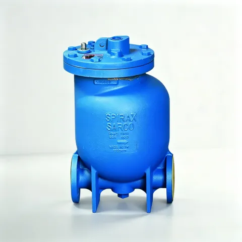
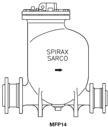
The Spirax Sarco MFP14 automatic pump is powered by steam or compressed air and is typically used to lift liquids such as condensate to a higher elevation. Under suitable conditions, it can drain equipment operating under vacuum or pressure directly. When used in conjunction with a ball float steam trap, it can effectively remove condensate from temperature-controlled heat exchangers under all operating conditions, including vacuum.
Available Versions
The MFP14 is available with the following body materials:
| Model | Body material |
|---|---|
| MFP14 | Ductile iron |
| MFP14S | Cast steel |
| MFP14SS | Stainless steel |
Standards
This product fully complies with the European Pressure Equipment Directive 97/23/EC and ATEX Directive 94/9/EC.
The CE and ® marks are available where required.
Certification
The MFP14 is available with EN 10204 3.1.B material certification.
The MFP14S and MFP14SS are designed in accordance with AD-Merkblätter and ASME VIII Div 1, and are available with EN 10204 3.1.B certification.
Note: Certification requirements must be specified when placing the order.
Note: For further information, refer to Technical Information sheet TI-P136-02.
2.2 Sizes and Pipe Connections
| Model | Connection type | Size |
|---|---|---|
| MFP14 | Threaded BSP (BS 21 parallel thread) | 1”, 1 1/2”, 2”, and 3” x 2” |
| MFP14 | Flanged EN 1092 PN16, ANSI B 16.5 Class 150, and JIS/KS B 2238 10 | DN25, DN40, DN50, and DN80 x DN50 |
| MFP14S | Threaded BSP/NPT | 2” and 3” x 2” |
| MFP14S | Flanged EN 1092 PN16, ANSI B 16.5 Class 150, and JIS/KS B 2238 10 | DN50 |
| MFP14S | 1/2” motive steam inlet and 1” exhaust connection, available with BSP/NPT threaded or SW socket-weld connections | - |
| MFP14SS | Threaded BSP (NPT connections also available as a special option) | 2” |
| MFP14SS | Flanged EN 1092 PN16, ANSI B 16.5 Class 150, and JIS/KS B 2238 10 | DN50 |
| MFP14SS | 1/2” motive steam inlet and 1” exhaust connection, available with BSP/NPT threaded or SW socket-weld connections | - |
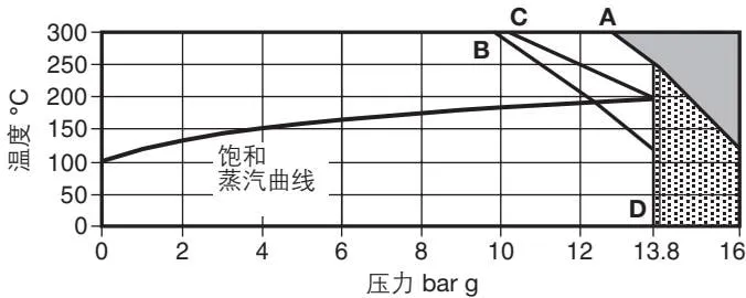
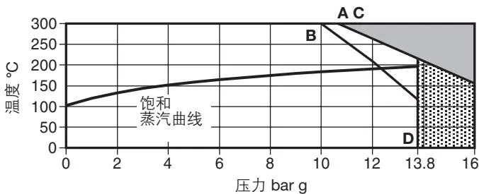
2.3 Pressure/Temperature Limits
(ADM/ASME Pressure Vessel Standard, Edition 5.0)
| Category | Model | Value |
|---|---|---|
| Valve body design conditions | PN16 | |
| Maximum motive medium inlet pressure (steam or other gas) | MFP14 and MFP14S | 13.8 bar g (PN16) |
| Maximum motive medium inlet pressure (steam or other gas) | MFP14SS | 10.96 bar g (PN16) |
| PMA maximum allowable pressure | MFP14 | 16 bar g @ 120°C |
| PMA maximum allowable pressure | MFP14S | 16 bar g @ 120°C |
| PMA maximum allowable pressure | MFP14SS | 16 bar g @ 93°C |
| TMA maximum allowable temperature | MFP14 | 300°C @ 12.8 bar g |
| TMA maximum allowable temperature | MFP14S | 300°C @ 10.8 bar g |
| TMA maximum allowable temperature | MFP14SS | 300°C @ 9.3 bar g |
| Minimum allowable temperature (consult Spirax Sarco for low-temperature applications) | 0°C | |
| PMO maximum operating pressure | MFP14 | 13.8 bar g @ 198°C |
| PMO maximum operating pressure | MFP14S | 13.8 bar g @ 198°C |
| PMO maximum operating pressure | MFP14SS | 10.96 bar g @ 188°C |
| TMO maximum operating temperature | MFP14 | 198°C @ 13.8 bar g |
| TMO maximum operating temperature | MFP14S | 198°C @ 13.8 bar g |
| TMO maximum operating temperature | MFP14SS | 188°C @ 10.96 bar g |
| Minimum operating temperature (consult Spirax Sarco for low-temperature applications) | 0°C |
The total head or backpressure (static head plus the pressure in the return system) must be lower than the motive medium inlet pressure. The total head is calculated as follows:
Height H (m) × 0.0981 + pressure in the return pipe (bar g) + fluid friction resistance in the downstream pipe (bar)
When calculating the fluid friction resistance in the downstream pipe, use a flow rate equal to the lesser of 6 times the actual condensate flow rate or 30000 L/h.
| Item | Value |
|---|---|
| Recommended inlet height (measured from the pump cover) | 0.3 m |
| Minimum inlet height (measured from the pump cover) | 0.15 m (reduced capacity) |
| Standard pumped liquid specific gravity | 1 to 0.8 |
| Item | DN40 and DN25 | DN50 | DN80 x DN50 |
|---|---|---|---|
| Pump displacement per cycle | 7 L | 12.8 L | 19.3 L |
| Steam consumption | Maximum 16 kg/h | Maximum 20 kg/h | Maximum 20 kg/h |
| Air consumption | Maximum 4.4 dm³/s | Maximum 5.6 dm³/s | Maximum 5.6 dm³/s |
| Temperature limits (ambient temperature range) | -10°C to 200°C | -10°C to 200°C | -10°C to 200°C |
MFP14
MFP14S
MFP14SS
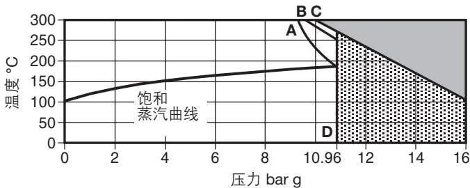

This product must not be used in this region.

Consult Spirax Sarco when using the product in this region - the product is not intended for use in this region.
A - D flange PN16 B - D flange JIS/KS 10 C - D flange ANSI 150
2.4 Materials
| No. | Component | Model | Material | Material standard |
|---|---|---|---|---|
| 1 | Pump cover | MFP14 | Ductile iron | (EN JS 1025) EN-GTS-400-18-LT |
| 1 | Pump cover | MFP14S | Cast steel | DIN GSC 25N/ASTM A216 WCB |
| 1 | Pump cover | MFP14SS | Stainless steel | BS EN 10213-4/ASTM A351 CF3M |
| 2 | Pump cover gasket | Synthetic fibre | ||
| 3 | Pump cover bolt | Stainless steel | ISO 3506 Gr. A2-70 | |
| 4 | Pump body | MFP14 | Ductile iron | (EN JS 1025) EN-GTS-400-18-LT |
| 4 | Pump body | MFP14S | Cast steel | DIN GSC 25N/ASTM A216 WCB |
| 4 | Pump body | MFP14SS | Stainless steel | 1998 - 1.4409/ASTM A351 CF3M |
| 5 | Pillar | MFP14 | BS 970, 431 S29 | |
| 5 | Pillar | MFP14S | Stainless steel | BS 970, 431 S29 |
| 5 | Pillar | MFP14SS | Stainless steel | BS 970, 303 S31 |
| 6 | Connecting rod | Stainless steel | BS 1449, 304 S11 | |
| 7 | Float and rod | Stainless steel | AISI 304 | |
| 8 | Integral lifting eye | MFP14 | Ductile iron | (EN JS 1025) EN-GTS-400-18-LT |
| 8 | Integral lifting eye | MFP14S | Cast steel | DIN GSC 25N/ASTM A216 WCB |
| 8 | Integral lifting eye | MFP14SS | Stainless steel | 1998 - 1.4409/ASTM A351 CF3M |
| 9 | Mechanism linkage | Stainless steel | BS 3146 pt. 2 ANC 2 | |
| 10 | Spring | Inconel 718 | ASTM 5962/ASTM B367 | |
| 11 | Plug | MFP14 | Steel | DIN 267 Part III Class 5.8 |
| 11 | Plug | MFP14S | Steel | DIN 267 Part III Class 5.8 |
| 11 | Drain plug | MFP14SS | Stainless steel | ASTM A182 - F316 |
| 12/12a | Check valve | Stainless steel | ||
| 13 | Threaded flange | MFP14 | Steel | |
| 13 | Connecting flange | MFP14S | Steel | DIN PN16/ANSI 150 |
| 13 | Connecting flange | MFP14SS | Stainless steel | ASTM A182 - F316L |
| 14 | Mechanism bracket | Stainless steel | BS 3146 pt. 2 ANC 4B | |
| 15 | Bracket bolt | Stainless steel | BS 6105 Gr. A2-70 | |
| 16 | Inlet valve seat | Stainless steel | BS 970, 431 S29 | |
| 17 | Inlet valve | Stainless steel | ASTM A276 440 B | |
| 18 | Inlet valve seat gasket | Stainless steel | BS 1449 409 S19 | |
| 19 | Exhaust valve seat | Stainless steel | BS 970 431 S29 | |
| 20 | Exhaust valve | Stainless steel | BS 3146 pt. 2 ANC 2 | |
| 21 | Exhaust valve seat gasket | Stainless steel | BS 1449 409 S19 | |
| 22 | EPM actuator | Aluminium-nickel-cobalt alloy | ||
| 23 | O-ring seal | EPDM | ||
| *24 | Pin rod | Stainless steel | BS 970 431 S29 | |
| *25 | Adjusting screw | Stainless steel | BS 6105 Grade A2 | |
| *26 | Adjusting screw | Stainless steel | BS 970 431 S29 | |
| *27 | Locking screw | Stainless steel | Grade A2 | |
| 28 | Spring anchor | Stainless steel | BS 970 431 S29 |
- Note: Refer to Figure 8 on page 18 for components 24, 25, 26 and 27.
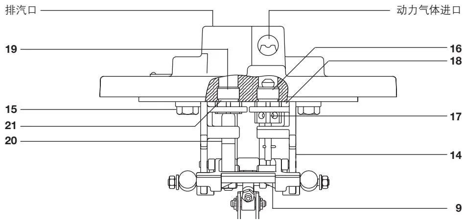
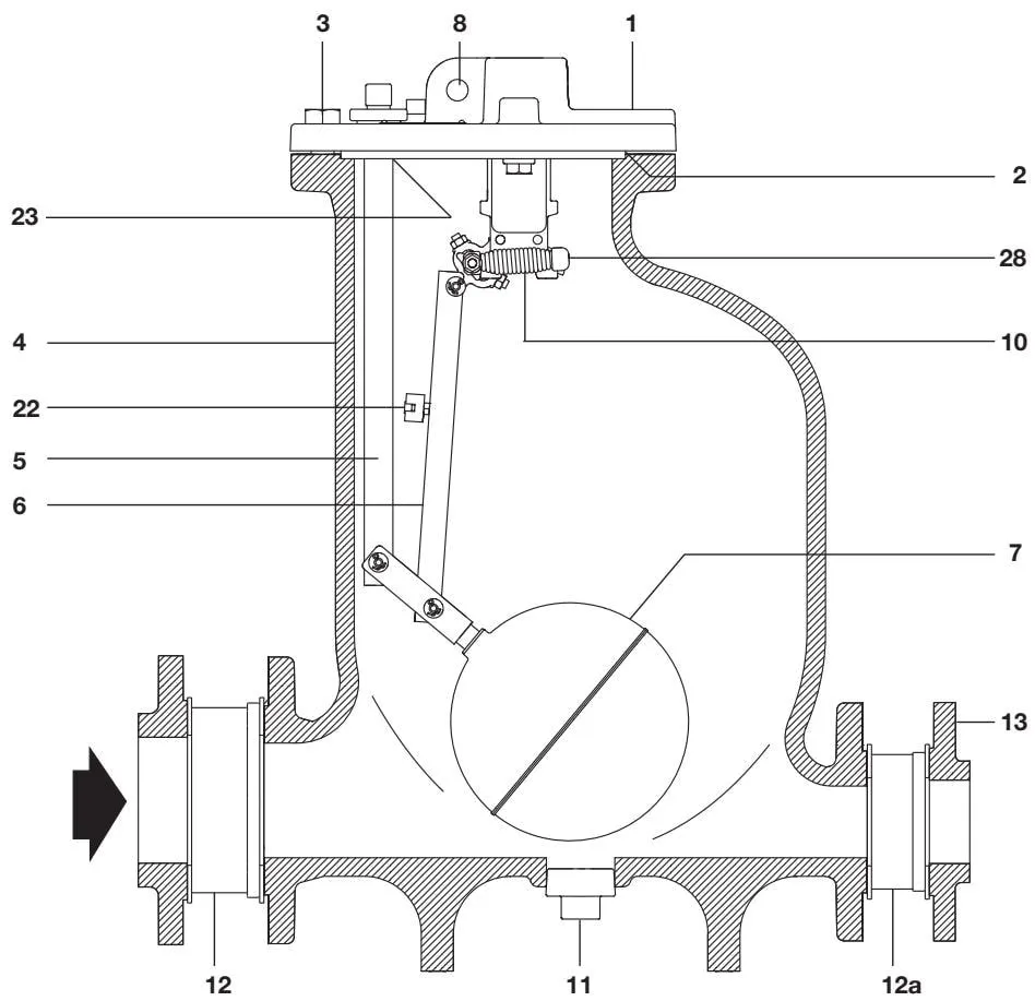
Figure 1 DN80 x DN50 MFP14 schematic
2.6 Approximate Dimensions/Weight
Metric (mm/kg)
MFP14
| Nominal size | A (JIS/KS PN) | A (ANSI) | B | C | *D | E | F | G | H | J | K | L | Weight - pump | Weight - including check valve and flanges |
|---|---|---|---|---|---|---|---|---|---|---|---|---|---|---|
| DN25 | 410 | - | 305 | 507 | - | 68 | 68 | 480 | 13 | 18 | 165 | ∅ 280 | 51 | 58 |
| DN40 | 440 | - | 305 | 527 | - | 81 | 81 | 480 | 13 | 18 | 165 | ∅ 280 | 54 | 63 |
| DN50 | 557 | 637.5 | 420 | 642 | - | 104 | 104 | 580 | 33 | 18 | 245 | ∅ 321 | 72 | 82 |
| DN80 x DN50 | 573 | 637.5 | 420 | 642 | 430 | 119 | 104 | 580 | 33 | 18 | 245 | 342 | 88 | 98 |
Imperial (in/lb)
MFP14
| Nominal size | A (JIS/KS PN) | A (ANSI) | B | C | *D | E | F | G | H | J | K | L | Weight - pump | Weight - including check valve and flanges |
|---|---|---|---|---|---|---|---|---|---|---|---|---|---|---|
| 1” | 16.1 | - | 12.0 | 19.9 | - | 2.7 | 2.7 | 18.9 | 0.5 | 0.7 | 6.5 | ∅ 11.0 | 112.4 | 127.8 |
| 1 1/2” | 16.1 | - | 12.0 | 20.7 | - | 3.2 | 3.2 | 18.9 | 0.5 | 0.7 | 6.5 | ∅ 11.0 | 119.0 | 138.9 |
| 2” | 21.9 | 25.0 | 16.5 | 25.3 | - | 4.1 | 4.1 | 22.8 | 1.3 | 0.7 | 9.6 | ∅ 12.6 | 158.7 | 180.8 |
| 3” x 2” | 22.6 | 25.0 | 16.5 | 25.3 | 16.9 | 4.7 | 4.1 | 22.8 | 1.3 | 0.7 | 9.6 | 13.6 | 160.9 | 189.6 |
Please note: Dimension K applies only to the DN80 x DN50 pump with an elliptical pump body. The pump bodies for DN25, DN40, and DN50 are circular; see Dimension D.
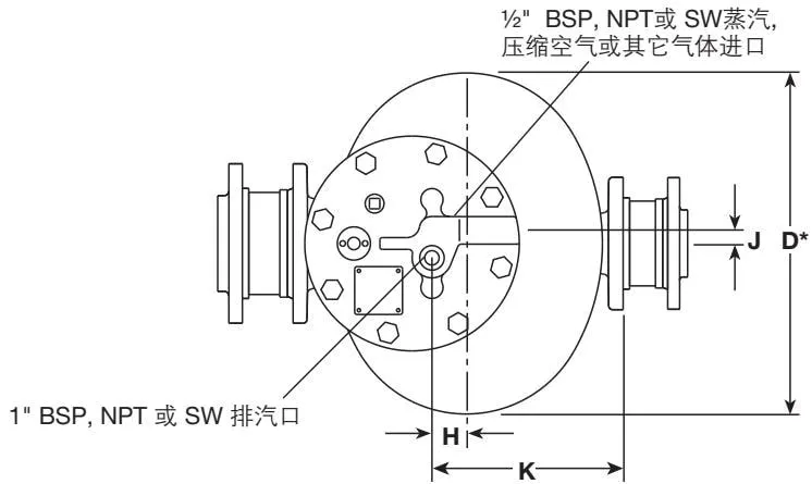
- Please note: Dimension D applies only to the DN80 x DN50 pump with an elliptical pump body. The pump bodies for DN25, DN40, and DN50 are circular; see Dimension L.
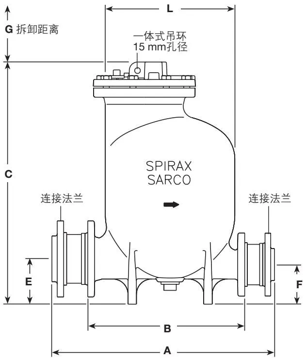
Figure 2 DN80 x DN50 MFP14 schematic
3. Installation
3.1 Installation - Open Systems
Caution: Before installation or maintenance, ensure that all steam, air, or other gas lines are isolated to prevent personal injury.
Ensure that any residual pressure in the pump or connecting pipework has been completely released. Also ensure that hot components have cooled to prevent burns. Wear protective clothing before carrying out installation or maintenance work.
The pump is fitted with an eye bolt for lifting. The eye bolt must not be loaded beyond the weight of the pump. Suitable lifting equipment must be used to ensure safe handling of the pump.
Note: If the pumped medium is flammable or explosive, the motive gas must be inert and oxygen-free.
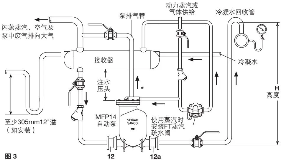
- Install the pump below the equipment to be drained, with the vent vertically upwards. The pump must be installed with the recommended filling head, which is the vertical distance between the top of the pump and the bottom of the receiver. See Figure 3. If the filling head changes, refer to the pump capacity tables.
- To prevent the equipment from flooding while the pump is discharging, install a receiver or receiver pipe horizontally above the pump and vent it to atmosphere. See Figure 3. Refer to Tables 1 and 2 to select the correct receiver size. All inlet piping must be full-bore.
- Check valve connections (12) and (12a) must ensure that the fluid flows through the valves in the correct direction. For optimum performance, keep the horizontal pipe upstream of the inlet check valve and downstream of the outlet check valve as short as possible. Connect the discharge pipe to the condensate return main or another return point. The bolt tightening torque for the inlet and outlet flanges is 76-84 N·m (56-62 lbf·ft).
- Connect the motive medium (steam, air, or other gas) to the inlet connection on the pump cover (see Figure 2 on page 11). Install a filter and a steam trap in the motive medium line. Drain the steam trap to the receiver or receiver pipe above the pump. Note: A maximum recommended differential between motive medium pressure and backpressure is 3 bar.
- The vent pipe connected to atmosphere must be reduced in diameter and unobstructed. The pipe should be as vertical as possible. If a horizontal pipe is unavoidable, it must be installed with sufficient slope to allow condensate to drain by gravity back to the pump or receiver. Refer to Table 3 for the recommended discharge pipe sizes.
3.2 Filling Head / Installation Height
Filling head and installation height are easily confused and must be carefully distinguished during calculation. Filling head is the distance from the top of the pump cover to the bottom of the receiver, while installation height is the distance from the bottom of the receiver to the floor.
| Item | Value |
|---|---|
| Filling head | Recommended 300 mm (12”), minimum 150 mm (6”), reduced capacity |
| Installation height | Maximum 1 m (39”) |
Note: To achieve the rated capacity, the check valves supplied by Spirax Sarco must be installed.
Table 1 Condensate Receiver Capacity
There must be sufficient storage space above the filling head to receive condensate. The receiver may be a large-diameter pipe or a tank. An overflow pipe should normally be installed as shown in Figure 3 and routed to a suitable drain. The overflow pipe must be connected close to the receiver and include a U-bend water seal of at least 305 mm.
| Pump size | Receiver size (metric) | Receiver size (imperial) |
|---|---|---|
| DN25 | 0.60 m x DN200 | 24” x 8” |
| DN40 | 0.60 m x DN200 | 24” x 8” |
| DN50 | 0.65 m x DN250 | 26” x 10” |
| DN80 x DN50 | 1.10 m x DN250 | 44” x 10” |
Table 2 Inlet Pipework without a Receiver
When the pump drains a single piece of equipment and no receiver is installed upstream of the pump, install sufficient pipework as shown in the tables below and use the recommended filling head. This prevents water from accumulating in the equipment while the pump is discharging.
The tables below specify the length of the receiver pipe above the pump when no receiver is installed.
Metric Pump sizes DN25, DN40, DN50, DN80 x DN50
| Liquid load (kg/h) | Inlet check valve and pipe size - DN25 (m) | DN40 (m) | DN50 (m) | DN80 x 50 (m) |
|---|---|---|---|---|
| <277 | 1.2 | - | - | - |
| 454 | 2.0 | 1.2 | - | - |
| 681 | 3.0 | 1.5 | 1.2 | - |
| 908 | 4.0 | 1.8 | 1.5 | - |
| 1 362 | - | 3.0 | 2.1 | - |
| 1 816 | - | 3.6 | 3.0 | - |
| 2 270 | - | - | 3.6 | 1.2 |
| 2 724 | - | - | - | 1.5 |
| 3 178 | - | - | - | 1.8 |
| 3 632 | - | - | - | 2.1 |
| 4 086 | - | - | - | 2.4 |
| 4 540 | - | - | - | 2.7 |
| 9 994 | - | - | - | 3.0 |
Imperial Pump sizes 1”, 1 1/2”, 2”, 3” x 2”
| Liquid load (lb/h) | Inlet check valve and pipe size - 1” (ft) | 1 1/2” (ft) | 2” (ft) | 3” x 2” (ft) |
|---|---|---|---|---|
| <598 | 3.9 | - | - | - |
| 546 | 6.6 | 3.9 | - | - |
| 1 500 | 9.8 | 4.9 | 4 | - |
| 2 000 | 13.1 | 5.9 | 5 | - |
| 3 000 | - | 9.8 | 7 | - |
| 4 000 | - | 11.8 | 10 | - |
| 5 000 | - | - | 12 | 4 |
| 6 000 | - | - | - | 5 |
| 7 000 | - | - | - | 6 |
| 8 000 | - | - | - | 7 |
| 9 000 | - | - | - | 8 |
| 10 000 | - | - | - | 9 |
| 11 000 | - | - | - | 10 |
Table 3 Receiver Discharge Outlet Sizes
The minimum vent outlet diameter is shown in the table below:
| Pump size | Pump size (imperial) | Receiver discharge outlet diameter | Receiver discharge outlet diameter (imperial) |
|---|---|---|---|
| DN25 | 1” | 50 mm | 2” |
| DN40 | 1 1/2” | 65 mm | 2 1/2” |
| DN50 | 2” | 80 mm | 3” |
| DN80 x DN50 | 3” x 2” | 100 mm | 4” |
3.3 Installation - Closed-loop Steam Systems
Note: A closed steam system is one in which the pump vent pipe returns to the steam space of the equipment being drained.
Caution:
Before installation or maintenance, ensure that all steam, air, or other gas lines are isolated to prevent personal injury. Ensure that any residual pressure in the pump or connecting pipework has been completely released. Also ensure that hot components have cooled to prevent burns. Wear protective clothing before carrying out installation or maintenance work.
The pump is fitted with an eye bolt for lifting, and the pump weighs 70 kg (154 lb). The eye bolt must not be loaded beyond the weight of the pump. Suitable lifting equipment must be used to ensure safe handling of the pump.
Note: If the pumped medium is flammable or explosive, the motive gas must be inert and oxygen-free.
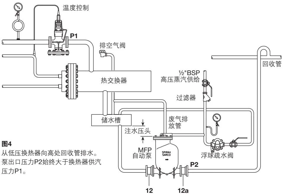
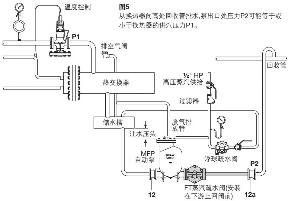
- Install the pump below the equipment to be drained, with the vent vertically upwards. The pump must be installed with the recommended filling head, which is the vertical distance between the top of the pump cover and the bottom of the receiver. See Figures 4 and 5 in Section 3.2. If the filling head changes, refer to the pump capacity tables.
- To prevent the equipment from flooding while the pump is discharging, install a receiver or receiver pipe horizontally above the pump. See Figure 4. Refer to Table 1 and Table 2, “Receiver Capacity,” on page 13 to select the correct receiver size. All inlet piping must be full-bore.
- Check valve connections (12) and (12a) must ensure that the fluid flows through the valves in the correct direction. For optimum performance, keep the horizontal pipe upstream of the inlet check valve and downstream of the outlet check valve as short as possible. Connect the discharge pipe to the condensate return pipe or another return point. The bolt tightening torque for the inlet and outlet flanges is 76-84 N·m (56-62 lbf·ft).
- Connect the motive medium (steam only) to the inlet connection on the pump cover. Install a filter and a steam trap upstream of the steam inlet pipe. Connect the steam trap drain to the receiver or receiver pipe above the pump. Note: The recommended differential between motive medium pressure and backpressure is 2-4 bar.
- Connect the vent pipe to the receiver with unobstructed pipework. In certain special cases, it may be connected to the inlet pipe between the control valve and the equipment or directly to the top of the equipment. Install a thermostatic air vent at the highest point of the vent pipe to discharge all non-condensable gases during equipment start-up. The vent pipe must be installed with sufficient slope to allow condensate to drain by gravity back to the pump or receiver.
- When the backpressure is lower than the pressure during equipment drainage, install a correctly sized float steam trap with a thermostatic air vent between the pump and the check valve. See Figure 5.
4. Commissioning
- Slowly open the MFP14 pump motive medium inlet valve to admit the motive medium into the pump, and check the operation of the steam trap.
- Open the condensate inlet pipe valve and the pump outlet isolation valve.
- Open all valves upstream of the pump to allow condensate to enter the receiver and fill the pump. The pump begins discharging when it is full of water.
- Observe the pump for any abnormal operating conditions. At the end of each cycle, the MFP14 pump produces an audible venting sound, with a cycle time as short as 8 seconds. If any abnormal condition is detected, check that the equipment has been installed correctly, referring to Section 8. Contact Spirax Sarco if necessary.
- If an overflow pipe is installed, check that it contains a water seal to prevent steam leakage from the equipment during normal operation. Fill the water seal if necessary.
5. Operation
- Before the pump starts operating, the float (7) is in its lowest position. The motive medium inlet valve (17) is closed and the vent valve (20) is open, as shown in Figure 6.
- The pumped fluid enters the pump body by gravity through the inlet check valve (12), causing the float (7) to rise.
- As the float (7) rises, it moves the mechanism (9) upwards, gradually increasing the tension in the spring (10). When the float (7) reaches its set position, the mechanism changes over rapidly. As the mechanism (9) accelerates upwards during changeover, the energy stored in the spring is released, opening the motive medium inlet valve and closing the vent valve, as shown in Figure 7.
- Steam enters the pump body through the motive medium inlet valve, increasing the pressure inside the pump. The increased pressure closes the inlet check valve (12), and the fluid is discharged downstream through the outlet check valve (12a).
- As the fluid is discharged from the pump body, the float descends and moves the mechanism (9) downwards, gradually increasing the tension in the spring (10) again. When the float (7) reaches its set position, the mechanism changes over rapidly again. As the mechanism (9) accelerates downwards during changeover, the energy stored in the spring is released, opening the vent valve and closing the motive medium inlet valve.
- Pressure in the pump is released through the vent valve. When the pressure in the pump falls to the same level as the inlet pipe pressure, the inlet check valve opens again. Fluid enters the pump again and the next cycle begins.
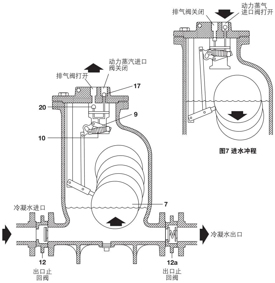
Figure 6 Inlet stroke
6. Maintenance
Mechanism Inspection and Maintenance
Caution: Before installation or maintenance, ensure that all steam, air, or other gas lines are isolated to prevent personal injury.
Before carrying out maintenance, identify the medium remaining inside the pump. Opening the pump without taking this precaution may cause environmental hazards or personal injury.
Ensure that any residual pressure in the pump or connected piping has been completely released.
Also ensure that hot components have cooled sufficiently to prevent burns. Wear suitable protective clothing before carrying out installation or maintenance work.
The pump is fitted with an eye bolt for lifting. The eye bolt must not be subjected to a load greater than the weight of the pump.
When dismantling the pump, take care to prevent injury from mechanism components under high spring force.
Handle with care.

Figure 8
- Disconnect all piping connected to the pump cover.
- Check the mechanism for foreign matter or scale and verify that it moves freely.
Caution: The locating bolts (items 25 and 26 in Figure 8) are set by the manufacturer and must not be adjusted during the following maintenance procedures.
- Inspect the springs (item 10 in Figure 9). If damaged, remove the split pins and washers, remove the spring assembly, and replace it with a new spring assembly (see the Spare Parts section: Spring Assembly). Install new split pins and washers, and apply a small amount of Loctite 620 adhesive to the threads of the pin rod.
- Inspect the inlet and exhaust valves:
a) Remove the pivot pin (item 24 in Figure 8) from the end of the mechanism connection. Turn the float and lever to the opposite side of the rod. b) Remove the split pin, washer, and spring from the driving pin. c) Remove the inlet-valve retaining nut. Note that Loctite 602 adhesive has been applied to it. d) Remove the mechanism-bracket nuts and remove the mechanism from the pump cover. e) To remove the exhaust valve, if necessary, loosen the main pivot pin on the exhaust-valve side of the bracket and remove the exhaust valve. This can be done by lifting the lever from the bottom of the bracket, tilting the bracket, and then lifting it out. Remove the exhaust valve from the lever. f) Remove the valve seats (and inlet valve) from the pump cover, noting their relative positions in the pump cover. The DN25 and DN40 valve seats can be identified by the two cut-out grooves in the exhaust valve and the single cut-out groove in the inlet valve; the inlet valve seats on DN50 and DN80 units have multiple holes. g) Inspect the inlet and exhaust valve-seat surfaces for wear (the inlet valve must be moved to the inspection seat). Clean the valve seats and reinstall them.
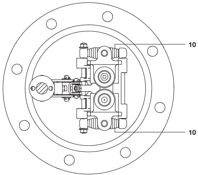
Figure 9
- Reassemble by reversing the above procedure, noting the following:
a) Ensure that the inlet and exhaust valve seats (and the inlet valve) are installed in the correct positions (refer to 4f). Tighten to 129-143 N·m (95-105 lbf·ft). b) Exhaust-valve assembly: Place the spring in the exhaust valve, position the valve on the lever, compress the spring, and tighten the retaining nut. c) Tighten the mechanism locating screws to 38-42 N·m (28-31 lbf·ft). d) Install a new split pin on the inlet-valve stem. e) Exhaust valve: Position the valve operating rod at the point nearest to the pump cover (exhaust valve closed). The valve should then be firmly against the valve seat. Turn the locating nut until it contacts the driving pin. Then back it off 3 3/4 turns for DN80 and DN50 pumps, and 2 3/4 turns for DN40 and DN25 pumps. Tighten the locknut.
- Replace the float: Loosen the float from the retaining bolt. When using a socket, remove the pin from the float arm. Connect the new float and lever using new bolts, washers, and Loctite 602 adhesive. If the pin on the float arm has been removed, install a new split pin and washer.
- When reinstalling the pump cover and mechanism assembly, note the pump-cover position mentioned above. Tighten the pump-cover screws to 121-134 N·m (89-99 lbf·ft). Operate the pump in accordance with the start-up procedure.
7. Spare Parts
Available spare parts are shown with solid lines in the figure below; components shown with dashed lines are not included in the supply.
Available Spare Parts
| Spare Part | Part Number |
|---|---|
| Pump-cover gasket | 2 |
| Float | 7 |
| Inlet and outlet check valves | 12 |
| Pump cover and internal mechanism assembly | 1, 2, 7 |
| Valve assembly (inlet and exhaust valves and valve seats) | 16, 17, 18, 19, 20, 21 |
| Spring assembly (pair of springs) | 10 |
| Mechanism assembly (including inlet and exhaust valves and retaining bolts) |
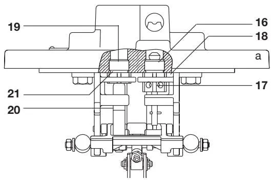
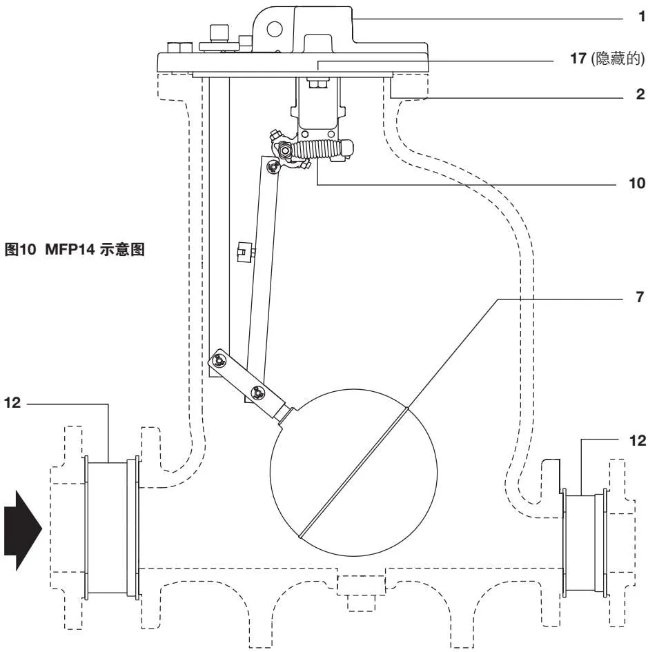
Figure 10 MFP14 schematic
8. Troubleshooting
If a correctly selected MFP14 pump does not operate properly, check for possible installation problems. For an existing installation, if the pump operates intermittently, the cause is usually a change in the motive gas supply or backpressure exceeding the original design parameters. After identifying the conditions and the fault shown in the figure below, check each item in sequence.
Note:
Installation and fault inspection must be carried out by qualified professionals. Before dismantling the pump or piping, ensure that the internal pressure has been fully released and the motive gas supply has been shut off to prevent accidents. Also ensure that the medium inside the pump will not harm the environment or personnel. When fully dismantling the unit, slowly remove the nuts/connecting pipes. This allows you to clearly determine whether pressure remains in the pipe before completely removing any fittings or components. Pressure must be released before any connection is disconnected.
Warning:
Before performing any dismantling operation, release the pressure inside the pump.
| Symptom/Cause | Description |
|---|---|
| Symptom 1 | The pump does not start |
| Cause 1a | Motive power is switched off |
| Check and diagnosis 1a | Open the valve to supply motive gas |
| Cause 1b | The condensate inlet line is shut off |
| Check and diagnosis 1b | Open all valves to allow condensate to reach the pump |
| Cause 1c | The condensate drain line is shut off |
| Check and diagnosis 1c | Open all valves to allow condensate to drain freely |
| Cause 1d | Motive pressure is insufficient to overcome backpressure |
| Check and diagnosis 1d | Check the motive pressure and static backpressure. Adjust the motive pressure to 0.6-1 bar above the static backpressure, or higher |
| Cause 1e | The check valve is installed in the wrong direction |
| Check and diagnosis 1e | Check whether the direction is correct and correct it if necessary |
| Cause 1f | Discharge is obstructed |
| Check and diagnosis 1f | In an open or closed system, ensure that the discharge line is connected to the pump or receiving tank without obstruction and is capable of draining by gravity |
| Symptom/Cause | Description |
|---|---|
| Symptom 2 | The motive gas line or equipment overflows, but the pump appears to operate normally (a timed discharge sound can be heard) |
| Cause 2a | The pump is undersized |
| Check and diagnosis 2a | Check whether the load exceeds the rated capacity (TI-P136-02). Increase the check valve size or install an additional pump as required |
| Cause 2b | Insufficient flooding head |
| Check and diagnosis 2b | Refer to page 12 and Section 3—reduce the pump size to meet the required flooding head |
| Cause 2c | Insufficient motive gas to achieve rated capacity |
| Check and diagnosis 2c | During operation, check the set motive pressure and maximum backpressure. Compare with the capacity table and increase the motive pressure to obtain the required capacity |
| Cause 2d | The condensate inlet line is obstructed |
| Check and diagnosis 2d | Use full-bore fittings. Clean the filter, if installed, and check that all valves are fully open |
| Cause 2e | The inlet and outlet check valves are stuck open (optional) |
| Check and diagnosis 2e | Isolate the check valve and release the piping pressure. Remove the check valve, inspect the disc and spring, clean the valve seat surfaces, and reinstall the valve. Replace it if necessary |
| Symptom/Cause | Description |
|---|---|
| Symptom 3 | The motive gas line/equipment overflows, and the pump stops operating (no timed discharge sound can be heard) |
| Cause 3a | The discharge line is shut off or blocked |
| Check and diagnosis 3a | Check the inlet pressure and static backpressure at the pump discharge outlet. If they are equal, the discharge line may be shut off or blocked. Check all downstream valves to ensure that there is no blockage |
| Cause 3b | The outlet check valve is closed |
| Check and diagnosis 3b | After checking 3(a), isolate the check valve and release the piping pressure. Remove and inspect the check valve, clean the valve seat surfaces, and reinstall the valve. Replace it if necessary |
| Cause 3c | Insufficient motive pressure |
| Check and diagnosis 3c | If the motive pressure is lower than the static backpressure, adjust the motive pressure to 0.6-1 bar above the static backpressure, or higher, but do not exceed the equipment pressure limit |
For items 3(d) through 3(g)—the discharge/return line must be isolated from the receiving equipment (closed system). Remove the discharge/return line connection from the pump cover.
Important safety notice:
For items (d) through (g), the discharge line and return line must be removed at the pump discharge outlet. In a closed system, to prevent personal injury, before opening the piping, ensure that the pump has been isolated (the motive gas, condensate inlet line, discharge line, and exhaust line, etc. have all been shut off) and that the pressure inside the pump has been released. In both open and closed systems, hot condensate may discharge forcefully from the pump outlet during a fault. Perform this operation carefully to prevent burns. Wear protective clothing/equipment. When dismantling the pump, take care to prevent injury from the stored force in the operating mechanism. Handle the pump carefully.
| Symptom/Cause | Description |
|---|---|
| Cause 3d | Inlet valve leakage or wear |
| Check and diagnosis 3d | Slowly open the motive gas line with the condensate inlet and outlet shut off. Observe whether significant steam or air leakage is present at the discharge outlet. If leakage is observed and it is not secondary steam, the inlet valve has failed. Isolate the pump, remove the pump cover and mechanism for inspection, and replace the inlet valve and valve seat assembly |
| Cause 3e | Mechanism failure: 1. Broken spring/pin; 2. Damaged float ball; 3. Distorted mechanism |
| Check and diagnosis 3e | Keep the motive gas supply open and slowly open the condensate inlet line to allow condensate to flow into the pump. Observe the discharge outlet, keeping personnel away from it. If condensate overflows from the discharge outlet without the pump mechanism operating, the mechanism has failed. Shut off the motive gas and condensate inlet, remove the pump cover and mechanism assembly for inspection, and check the spring or float ball for obvious damage. Manually operate the mechanism and check for distortion or increased friction. Repair and/or replace any faulty components |
| Cause 3f | Steam lock caused by discharge or return flow (open or closed system) |
| Check and diagnosis 3f | If the mechanism operating sound can be heard but no fluid flows from the discharge line, slowly open the pump drain line and observe the pump operation. Personnel must remain away from the discharge outlet. If the pump operates normally, the discharge or return line may be faulty. Recheck whether the piping arrangement of the discharge/return line complies with the installation instructions. The discharge/return line must be capable of draining by gravity to prevent steam from forming a vapor lock in the pump. In a closed system, install a thermostatic air vent on the balance line |
| Cause 3g | The inlet check valve is stuck closed |
| Check and diagnosis 3g | If the mechanism does not operate and no fluid overflows from the discharge outlet, the fault may be in the condensate inlet section. Confirm that all valves before the pump are open. If they are open, the check valve may be blocked or the flooding head may be insufficient. Separate the pump and check valve, release the piping pressure, and remove the check valve for inspection. Clean the valve seat surfaces and reinstall the valve. Replace it if necessary. Reinstall the new discharge/return line and open the line |
| Cause 3h | The inlet filter is blocked |
| Check and diagnosis 3h | Close the shut-off valve before the filter, remove the screen, and clean it in water. Replace the screen with a new one if necessary. Reinstall the filter and open the shut-off valve |
| Symptom/Cause | Description |
|---|---|
| Symptom 4 | The pump vibrates or produces a “banging” noise in the condensate return main after discharging condensate |
| Cause 4a | A vacuum is generated at the pump discharge outlet due to the acceleration or deceleration of a large quantity of water in the return line, usually caused by long-distance transport or multiple rises and drops |
| Check and diagnosis 4a | Install a vacuum breaker at the high point of the return line. For a pressurized condensate return system, install an air vent downstream of the vacuum breaker. Consult Spirax Sarco |
| Cause 4b | Pump air leakage |
| Check and diagnosis 4b | Check the condensate inlet pressure and the static backpressure at the discharge outlet. If the inlet pressure is equal to or greater than the static backpressure, air leakage may occur. In an open system, check whether the steam trap discharging condensate to the inlet line is leaking, as this will increase the inlet line pressure. Replace the faulty steam trap. In a closed system, during normal operation, if the condensate inlet pressure exceeds the static backpressure, for example, by adjusting the control valve or reducing the static pressure in the condensate return line to increase the equipment operating pressure, a pump/steam trap combination installation must be used. This installation prevents steam from entering the main return line while allowing the pump to operate normally when condensate is present (see Figure 5 on page 15) |
| Cause 4c | Excessive differential pressure. If the motive steam pressure exceeds the pump backpressure by too much, the temperature of the discharged condensate will also increase. When the flash steam generated by high-temperature condensate encounters cooler condensate in the condensate return circuit, it produces a steam-water impact noise |
| Check and diagnosis 4c | It is strongly recommended that the motive steam pressure not exceed the possible total backpressure by more than 2-4 bar. If the motive steam comes from a higher-pressure line, reduce the pressure appropriately before use |
| Symptom/Cause | Description |
|---|---|
| Symptom 5 | Excess secondary steam is discharged through the discharge line (open equipment only) |
| Cause 5a | Steam trap leakage, discharging steam directly into the condensate line (see also 4(b)) |
| Check and diagnosis 5a | Check whether the steam trap is leaking. Repair or replace the steam trap |
| Cause 5b | Excess secondary steam (more than 20 kg/h (45 lb/h)) is discharged through the discharge line |
| Check and diagnosis 5b | Drain the storage tank or storage pipe upstream of the pump |
| Cause 5c | The discharge valve is blocked or worn |
| Check and diagnosis 5c | Isolate the pump, remove the pump cover and mechanism, and remove the discharge valve and valve seat assembly. Inspect and clean the valve seat surfaces, then reinstall the valve. Replace it if worn |