1. Safety Information
Spirax Sarco products are designed, manufactured and tested to rigorous standards to meet the requirements of modern industry.
Safe operation of this product can only be guaranteed if it is properly installed, commissioned and maintained by suitably qualified personnel in accordance with the operating instructions. See Section 1.1, Safety Information. General installation and safety instructions for pipeline and plant construction must also be observed, together with the proper use of tools and appropriate safety equipment.
The product is designed and constructed to withstand the stresses encountered during normal use. Using the product for any other purpose, or installing it incorrectly without following the installation and maintenance instructions, may damage the product and result in injury or fatality.
1.1 Preparation for Use
Refer to the Installation and Maintenance Instructions, nameplate and TIS to ensure that the product is suitable for the intended application. The products listed below comply with the European Pressure Equipment Directive 97/23/EC and carry the CE mark. The products fall within the following pressure equipment categories.
| Product | Group 2 gases |
| BDV60/3 | 3 |
| BDV60/4 | 3 |
| BDV60/5 | 3 |
| BDV60/6 | 3 |
| BDV60/8 | 4 |
| BDV60/10 | 4 |
I) The product has been specifically designed for use with steam as defined in the Group 2 Pressure Equipment Directive. For use with other fluids, contact Spirax Sarco to confirm the suitability of the product for the intended application.
II) Check that the material is suitable and that the pressure and temperature limits, including their maximum and minimum values, are appropriate. If the maximum operating limits of the product are lower than those of the system in which it is to be installed, or if a product malfunction could result in overpressure or overtemperature, ensure that a safety device is included in the system to prevent such conditions.
III) Determine the correct installation position and fluid flow direction.
IV) Spirax Sarco products are not designed to withstand external stresses imposed by the system in which they are installed. It is the responsibility of the installer to consider these stresses and take adequate precautions to minimise them.
V) Remove all connection protective covers and nameplate protective film before installation in steam or other high-temperature applications.
1.2 Access
Ensure safe access. A safe working platform is required before operating the product. Arrange suitable lifting equipment where necessary.
1.3 Lighting
Ensure adequate lighting, particularly when carrying out complex work.
1.4 Hazardous Liquids or Gases in the Pipeline
Consider the contents of the pipeline and the condition of the medium. Consider flammable substances, substances hazardous to health and substances at extreme temperatures.
1.5 Hazardous Environment Around the Product
Consider explosion risks, oxygen deficiency, such as in tanks and pits, temperature extremes, hot surfaces, fire hazards, such as during welding, excessive noise and moving machinery.
1.6 The System
Consider the effect on the complete system when carrying out work. Will any action, for example closing isolation valves or electrical isolation, put any other part of the system or personnel at risk?
Hazards may include isolation of vents or protective devices, or the failure of controls or alarms. Ensure that isolation valves are opened and closed slowly to avoid system shocks.
1.7 Temperature
After isolating valves, allow the product to cool to ambient temperature to prevent burns.
1.8 Tools and Consumables
Before starting work, ensure that suitable tools and consumables are available. Use only genuine Spirax Sarco replacement parts.
1.9 Protective Clothing
Consider whether protective clothing is required to protect against hazards such as chemicals, high or low temperatures, noise, falling objects, and hazards to the eyes and face.
1.10 Permit to Work
All work must be carried out or supervised by suitably competent personnel. Installation and maintenance personnel must be trained in the correct use of the product in accordance with these instructions.
Where a formal permit-to-work system is in force, it must be complied with. Where no such system exists, it is recommended that a responsible person is aware of the work being carried out and, where necessary, arranges for a person responsible for safety. Warning notices may be posted where required.
1.11 Handling
Manual handling of Spirax Sarco products may present a risk of injury. Lifting, pushing, pulling, carrying or supporting a load may cause injury, particularly to the back. It is recommended that the risk be assessed, taking into account the task, the individual, the load and the working environment, and that the correct handling method be used.
1.12 Other Hazards
Under normal operating conditions, the external surface of this product may be very hot. When operated at the maximum permitted operating temperature, the surface temperature of some products may reach 171°C.
Many products are not self-draining. Take care when dismantling or removing the product from an installation. Refer to the Maintenance Instructions.
1.13 Freezing
For products that are not self-draining, where operation is not possible at ambient temperatures below freezing, protection must be provided to prevent freezing. The vessel must be completely thawed before use. To prevent the vessel temperature from falling below -10°C (14°F) during operation, coil heating may be considered.
1.14 Disposal
This product is recyclable. No ecological hazard is anticipated with the appropriate disposal of the product.
1.15 Returning Products
When returning products to Spirax Sarco, customers and distributors must comply with UK and EC Health, Safety and Environment legislation. Information on any hazards and precautions required must be provided where residues or mechanical damage could present a health, safety or environmental hazard. This information must include safety data for any substances identified as hazardous to health or safety.
2. Product-Specific Safety Information
The following information is specific to this product and should be read in conjunction with the product safety information in Section 1.
Warning
If this product is not used as specified in this IMI, the protection provided may be impaired.
2.1 Overpressure Protection
The flash steam outlet connection must not be obstructed, otherwise the internal pressure may easily rise above atmospheric pressure.
Therefore, this product does not require any safety device.
2.2 Guard Rails
To prevent burns caused by contact with hot surfaces of the blowdown vessel or pipework, guard rails or protective screens must be installed around the blowdown vessel.
2.3 Associated Equipment
For ease of operation, ensure that associated equipment is connected to the blowdown vessel in accordance with the relevant technical and installation information.
3. Product Information
3.1 Description
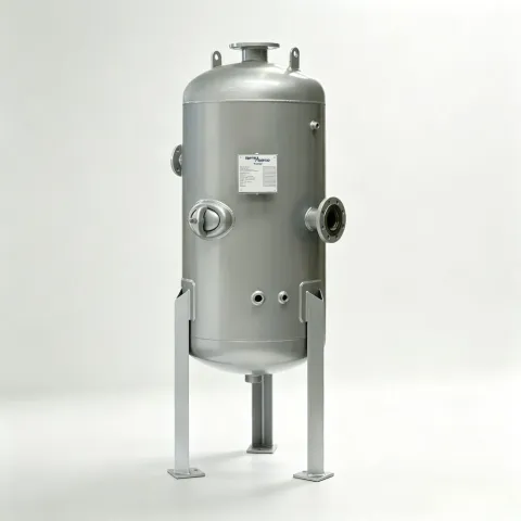
Spirax Sarco products are designed, manufactured and tested to rigorous standards to meet the requirements of modern industry. They comply with current safety and design standards and, when selected, installed and maintained in accordance with Spirax Sarco recommendations, provide long service life. The BDV60 blowdown vessel is designed and constructed in accordance with the European Pressure Equipment Directive 97/23/EC.
The blowdown vessel is particularly suitable for receiving discharge water from manually or automatically controlled bottom blowdown valves, manually controlled continuous blowdown discharge valves, TDS automatic control valves and control systems, vessels, other ancillary equipment and heat recovery systems.
These Installation and Maintenance Instructions provide comprehensive information on operation, installation and maintenance and should preferably be read before using the product.
3.2 Technical Data
| Construction material | Carbon steel |
| Surface coating | Blue heat-resistant paint |
3.3 Pressure/Temperature Limits
Note:
For boiler blowdown applications, to comply with HSE Guidance Note PM60, the internal vessel pressure must not exceed 0.35 barg (5 psi g).
| Body design conditions | PN16 | |
| Maximum design pressure | 7 bar g @ 171°C | (101 psi g @ 340°F) |
| Maximum design temperature | 171°C @ 7 bar g | (340°F @ 101 psi g) |
| Minimum design temperature | -10°C | (14°F) |
| Maximum operating pressure, refer to PM60 | 0.35 bar g | (5 psi g) |
| Minimum operating temperature, refer to PM60 | 109°C | (228°F) |
| Minimum operating temperature | 0°C | (32°F) |
| Maximum design hydrostatic test pressure | 10 bar g | (145 psi g) |
Note: Testing is in accordance with the European Pressure Equipment Directive 97/23/EC.
BDV60 Blowdown Vessel
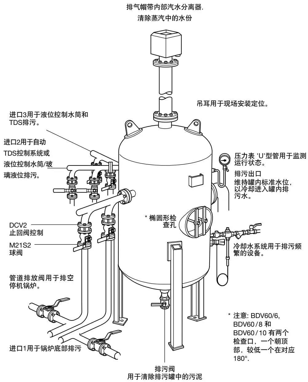
Note: Inlet 1 is for boiler bottom blowdown. Inlets 2 and 3 are internally interchangeable for water level control chamber/gauge glass blowdown and TDS blowdown.
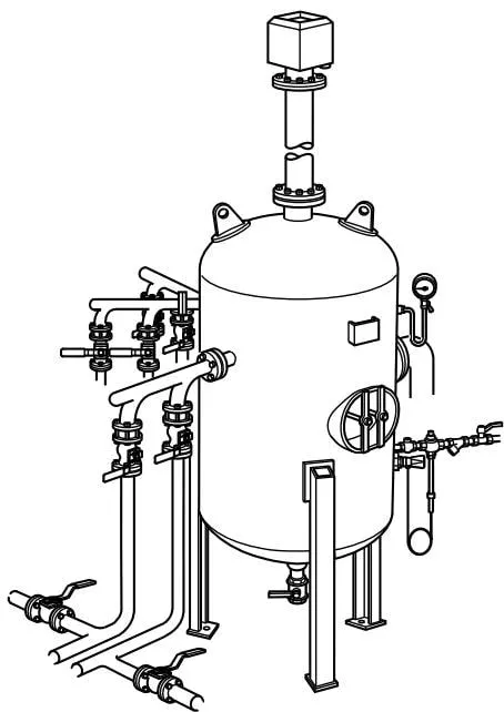
Figure 2 Typical blowdown vessel arrangement
4. Installation
Read Sections 1 and 2, ‘Safety Information’, before installation.
Ensure that all plugs or blanking plates supplied with the equipment are securely fitted at ambient and operating temperatures.
A flash steam outlet must be installed at the very top of the blowdown vessel, as shown in Figure 2. Each blowdown vessel is provided with a 3/8” BSP connection for a pressure gauge, U-tube and cock. Refer to Table 1 for the number of support legs and bolt-hole dimensions.
The flash steam outlet connection must not be obstructed in any way, as this may cause the vessel pressure to exceed atmospheric pressure.
This product does not require any safety devices to be installed.
Table 1 Fixing bolts
The blowdown vessel support legs have pre-drilled holes for fixing bolts (dimensions as follows):-
| Blowdown vessel | Number of support legs | PCD of bolt holes |
| BDV60/3 | 3 | ∅ 14 mm (9/16") on a 406.0 mm PCD |
| BDV60/4 | 3 | ∅ 19 mm (3/4") on a 536.0 mm PCD |
| BDV60/5 | 3 | ∅ 19 mm (3/4") on a 679.0 mm PCD |
| BDV60/6 | 3 | ∅ 19 mm (3/4") on a 833.0 mm PCD |
| BDV60/8 | 3 | ∅ 19 mm (3/4") on a 1126.0 mm PCD |
| BDV60/10 | 4 | ∅ 19 mm (3/4") on a 1376.0 mm PCD |
4.1 Positioning:
- Use the lifting lugs to position the blowdown vessel.
- Ensure that access to the inspection opening is unobstructed.
- Remove all plastic caps from the blowdown vessel connections.
- Cap unused connections. Warning: Do not cap the vent or outlet.
- Use a spirit level to check that the blowdown vessel is vertical. This is essential for optimum performance. If necessary, fit incompressible shims beneath the support legs.
4.2 Blowdown vessel site pipework
We provide as much guidance and technical information as possible to assist with system pipework/valve connections.
For final connection of the blowdown vessel to the system pipework, refer to the separate port dimension technical data. Use the final position of the blowdown vessel to determine the level and accurate routing of each individual port to the pipework system.
4.3 Inlet arrangement
Install inlet pipework below the bottom of the blowdown vessel. This ensures that the blowdown pipework remains full of water, reducing the effects of water hammer. Use the correct isolating valves and check valves, or a combination of both, to prevent backflow between the different pipework connections on the blowdown vessel.
Note: Inlet 1 (Figure 2 on page 7) may only be used for boiler bottom blowdown. Inlets 2 and 3 are internally interchangeable and may be used for level control chamber/gauge glass blowdown and TDS blowdown.
4.4 Vent arrangement
Install the vent pipe as vertically as possible. Where a horizontal vent pipe is required, it must be installed with a slight fall towards the blowdown vessel. It must not be connected to other vent pipes.
Warning: Do not install isolating valves or check valves in the vent pipe.
A flanged straight section is recommended between the blowdown vessel and vent pipe to facilitate installation of a blanking plate during hydrostatic testing.
We strongly recommend using a Spirax Sarco vent head to remove entrained moisture and protect nearby personnel and buildings.
Connect the vent head drain to a suitable drain point, preferably with an air break, which may take the form of a funnel. Do not connect the drain to the blowdown vessel.
4.5 Outlet
Connect the outlet drain pipework. The drain pipework must be below the blowdown vessel.
Warning: Do not install isolating valves or check valves in the outlet pipework. A flanged straight section is recommended between the blowdown vessel and outlet pipework.
This allows easier removal after hydrostatic testing.
4.6 Cooling water system
All blowdown vessels have two cooling water system connections: one for the temperature sensor and the other for cooling water. Install the control system as described in the installation and maintenance instructions supplied with the product.
Set the operating temperature below 43°C, which is also the maximum permitted water discharge temperature (UK standard).
4.7 Surface paint
The blowdown vessel surface is protected by a coat of blue paint. Touch up the paint if it is damaged during installation or transport.
4.8 Frost protection
If the blowdown vessel is installed outdoors, temperature protection must be considered to prevent water from freezing.
Use trace heating in extreme conditions.
5. Commissioning
Before putting the product into service, ensure that:
- Blanking plates and plugs are tightened. Tighten the blanking plates and plugs when the blowdown vessel reaches operating temperature.
Note: Maximum operating temperature 171°C @7bar g ( 340° F @101psi g). - All connections to pipework equipment are secure, with no additional stresses applied to the blowdown vessel.
- No foreign materials are present inside the vessel.
- The vessel is filled with water to the normal operating level.
6. Operation
Operation of the blowdown vessel is straightforward and does not require special instructions. The blowdown vessel allows hot water to expand from high pressure to low pressure, producing a quantity of flash steam.
Before use and after draining the blowdown vessel, it must be refilled to the normal operating water level (the water level is at the centreline of the blowdown vessel outlet) until water discharges from the outlet.
The blowdown vessel is designed to operate at high temperatures. Personnel must take care to avoid scalding, as the blowdown vessel normally dissipates heat only slowly.
We recommend checking the pressure gauge reading on the blowdown vessel during blowdown.
If it indicates more than 0.35barg (5 psi g), this indicates that the vent or outlet is blocked and requires immediate attention.
Warning: Before operating/testing bottom blowdown valves, automatic TDS control systems, level control systems, or other equipment that may discharge to the blowdown vessel, confirm that the isolating valves on the blowdown vessel/header are fully open.
This is particularly important for level control systems, as the level control may appear to operate correctly without being tested and may be incorrect.
Operating conditions
| Spirax Sarco blowdown vessel designed to operate at: | 7 barg @ 171°C (101 psig @ 340°F) | |
| Minimum operating temperature: | 0°C | (32°F) |
7. Maintenance
Warning:
Isolate the blowdown vessel by closing the inlet isolating valve, closing all blowdown valves, and opening valves on all other pipework (for example, following the double block and bleed principle).
Repair of pressure vessels is not recommended, as it requires specialist design, welding and re-inspection by qualified personnel.
6-month inspection
The blowdown vessel must be drained every 6 months to remove accumulated blowdown water/sludge. Sludge inside the blowdown vessel should be flushed through the inspection/access opening using a hose, with the blowdown valve open.
After draining/flushing and before reuse, refill the vessel to the normal operating water level (the water level is at the centreline of the blowdown vessel outlet) until water discharges from the outlet.
14-month inspection
The blowdown vessel should be thoroughly inspected by qualified personnel every 14 months or at every major boiler inspection. The inspection normally includes an internal surface inspection to ensure that there is no excessive corrosion, erosion or scaling, together with dimensional checks or checks for other obstructions in the vessel vent, outlet or outlet anti-siphon pipe.
Qualified personnel should determine the areas requiring inspection and take the necessary action.
A new gasket must be fitted each time the inspection opening is reinstalled after opening (see Section 8, Spare parts).
The table below gives the inspection opening dimensions for each blowdown vessel model:
| Capacity designation | Inspection opening |
| BDV60/3, BDV60/4, BDV60/5 | Oval inspection opening, 150 x 100 mm |
| BDV60/6, BDV60/8, BDV60/10 | 2 x oval inspection openings, 150 x 100 mm |
Note:
The blowdown vessel should have a written inspection schedule, with the inspection frequency determined by qualified personnel.
8. Spare parts
Only gaskets are available as blowdown vessel spare parts.
Available spare parts - inspection opening gaskets
| Vessel type | |||
| BDV60/3 | Outside dimensions 180 x 130 mm | 1 oval gasket, Spirax Sarco spare part number | 4050181 |
| BDV60/4 | |||
| BDV60/5 | |||
| BDV60/6 | Outside dimensions 180 x 130 mm | 2 oval gaskets, Spirax Sarco spare part number | 4050181 |
| BDV60/8 | |||
| BDV60/10 | |||
Ordering spare parts
Example: 1 Spirax Sarco BDV60/3 inspection opening gasket - spare part number 4050181.