- Safety information
- Product and delivery information
- System overview
- Mechanical installation
- Electrical installation
- Commissioning
- Quick setup
- Complete setup
- Communications
- Maintenance
- Fault diagnosis
- Technical information
- Default settings
- Appendix
- Overview of the Modbus protocol
1. Safety information
The safe operation of this product can only be guaranteed when it is correctly installed, commissioned, used and maintained by qualified personnel in accordance with the operating instructions (see Section 1.11). The general installation and safety guidelines for pipework and equipment must be observed during installation, together with the correct use of tools and safety equipment.
In the UK, IEE regulations (BS 7671) must be followed. In other regions, the applicable local regulations must be observed.
All wiring materials and procedures must comply with the relevant EN and IEC standards.
Warning
This product is designed and manufactured to withstand external forces encountered during normal use. If this product is not used as a boiler controller, or if installation procedures do not comply with the instructions in this manual, the following may occur during product improvement or repair:
- Personal injury or death;
- Product or property damage;
- Invalidation of the CE marking;
These instructions should always be kept in a safe place close to the product installation location.
Warning
This product complies with the Electromagnetic Compatibility Directive 2004/108/EC and satisfies all of its requirements.
The product is suitable for Class A environments, such as industrial environments. Comprehensive and detailed EMC testing has been performed. Under the following conditions, the product may be exposed to interference exceeding the immunity limits for heavy industrial environments. The relevant serial number is UK Supply BH BT105020080:
- The product or its connecting cables are located near a radio transmitter;
- Interference is present on the mains power supply. If interference is likely, a power line protector should be installed. The protector should provide filtering, rectification, surge and peak protection.
- The use of mobile radios and mobile phones within approximately 1 metre of the product or its connecting cables may cause interference. The actual safe distance will vary depending on site conditions.
The product complies with the Low Voltage Directive (2006/95/EC) and meets the following standard:
- EN61010-1:2001, Safety requirements for electrical equipment for measurement, control and laboratory use;
Electrostatic discharge (ESD)
Care must be taken to prevent electrostatic discharge and avoid damage to the product.
1.1 Intended use
i) Check that the product is suitable for the fluid being controlled. ii) Check the material suitability and the maximum and minimum pressure and temperature values. If the maximum operating range of the product is lower than that of the system in which it is to be installed, or if product failure could result in a dangerous overtemperature or overpressure condition, a safety device must be installed in the system to protect against such limit conditions. iii) Determine the correct product installation position and fluid flow direction. iv) Spirax Sarco products cannot withstand external stresses. Installers must consider system stresses and take suitable precautions to minimise them. v) Before installing the product in steam or high-temperature service, remove all protective covers from the connections and the protective film from the nameplate.
1.2 Access
Before carrying out any operation, ensure that access is safe. If necessary, provide a safe working platform with suitable protection. Arrange suitable lifting equipment where required.
1.3 Lighting
Ensure that adequate lighting is provided, particularly where detailed or complex work is required.
1.4 Hazardous liquids or gases in the pipework
Consider what fluids may be present or may have been present in the pipework. Factors to consider include whether the fluid is flammable, hazardous to health, or subject to extreme temperatures.
1.5 Hazardous environments around the product
Consider the following: explosive atmospheres, lack of oxygen such as in containers or pits, hazardous gases, extreme temperatures, hot surfaces, fire hazards during welding, excessive noise and moving machinery.
1.6 The system
Consider the effect of the planned operation on the entire system. Could the planned action, such as closing isolation valves or switching off the power supply, put other parts of the system or personnel at risk?
Hazards may arise from the isolation of discharges or protective devices, or the disabling of controls or alarms. Isolation valves must be opened and closed slowly to prevent system shocks.
1.7 Pressure systems
Ensure that all pressure has been isolated and safely vented to atmospheric pressure. Consider double isolation and locking and tagging closed valves. Do not assume that the system is depressurised even when a pressure gauge indicates zero.
1.8 Temperature
After isolation, allow sufficient time for the equipment to cool to ambient temperature to avoid burns.
1.9 Tools and spares
Before starting work, ensure that suitable tools and readily replaceable spare parts are available. Use only genuine spare parts supplied by Spirax Sarco.
1.10 Protective clothing
Consider whether you and nearby personnel need protective clothing to protect against hazards such as chemicals, high or low temperatures, radiation, noise, falling objects, and eye or facial injuries.
1.11 Work permits
All work must be carried out or supervised by suitably competent personnel. Installation and maintenance personnel must be trained in the correct operation of the product in accordance with the installation and maintenance instructions.
Follow the formal work permit system and strictly comply with the procedures described above. Where no such system exists, the responsible person should be aware of the work being carried out and arrange for an assistant to be responsible for safety where necessary.
Post warning notices where required.
1.12 Manual handling
Manual handling of large or heavy items may cause danger or personal injury. Lifting, pulling, pushing, carrying or supporting loads by physical force can cause injury, particularly back injuries. Customers are advised to assess the risks associated with the task, personnel, workload and working environment and to use suitable handling methods accordingly.
1.13 Residual hazards
Under normal conditions, the external surfaces of the product may become very hot.
Many products do not have a self-draining function. Take extreme care when dismantling the product.
1.14 Freezing
When the product is exposed to temperatures below 0°C, valves without a self-draining function may be damaged by freezing. Suitable protective measures must be taken.
1.15 Disposal
When disposing of this product, take suitable precautions in accordance with local regulations.
Unless otherwise stated in the installation and maintenance instructions, this product is recyclable and presents no ecological hazard when disposed of properly.
1.16 Returning products
Customers and stockists are reminded that, under EC health, safety and environmental legislation, when returning products to Spirax Sarco, customers must provide information about hazards and any precautions taken when handling contaminated residues or mechanical damage. Such contamination or mechanical damage may present risks to health, safety or the environment. Relevant safety data sheets for any hazardous or potentially hazardous substances must be provided in writing.
2. Product and delivery information
2.1 Introduction
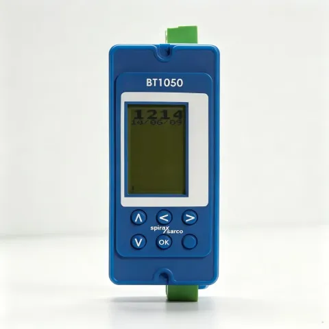
BT1050 is a timer for controlling a boiler bottom blowdown valve.
By controlling the opening and closing of the boiler bottom blowdown valve, solid impurities deposited at the bottom of the boiler are removed, preventing damage to the boiler.
The product can be mounted on a panel, DIN rail or baseplate and is powered by a 99-264V AC supply.
2.2 Front panel
The front panel has an LCD and five buttons:
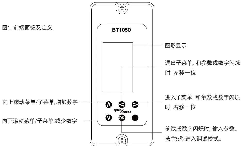 BT1050 front panel and button definitions
A and V buttons:
- Scroll up and down through the main menu and submenus
- Increase and decrease values in the main menu and submenus
◀ and ▶ buttons:
- Exit and enter submenus
- Move left or right in the main menu and submenus
OK button:
- Confirm an entry when a value or parameter is flashing
- Enter commissioning mode (press and hold for 5 seconds)
Commissioning mode allows product parameters to be configured, outputs to be set and tested, and the password to be changed. See Section 6.
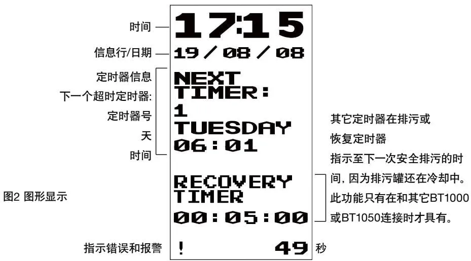 Graphic display interface
The parameter being edited is always shown in the lower-right corner of the screen. Press the OK button to enter a new parameter. Use the A and V buttons to scroll through the data; the previously entered selection will flash.
In operating (normal) mode, the display consists of four main sections:
Current time.
Information line/date.
Timer information.
Recovery time.
Use the software menu to select the operating parameters.
2.3 Information line details (in order of priority)
Alarm:
‘TEST ALM’ - The user is testing the alarm relay. The relay remains energised or de-energised for five minutes. See the TEST-OUTPUT-ALARM menu in commissioning mode.
‘ALARM’ - An error or fault has occurred. See the fault screen in operating mode and Section 9, ‘Fault diagnosis’.
Bottom blowdown valve (BB):
- ‘TEST BB’ - Tests the bottom blowdown valve relay. The relay remains energised or de-energised for five minutes. See the TEST-OUTPUT-VALVE menu in commissioning mode.
- ‘MAN OFF’ - The timer is stopped, that is, manual operation. The timer ignores the pre-programmed times. See the MODE-OFF menu in commissioning mode.
- ‘MAN OPEN’ - The timer is open, that is, manual operation. The timer ignores the pre-programmed times. See the MODE-ON menu in commissioning mode.
- ‘DELAYED’ - The blowdown valve opening is delayed until the RECOVERY TIMER has finished counting, after which the valve opens.
- ‘BLOWDOWN’ - Timed blowdown, that is, the blowdown valve is open.
2.4 Alarm/fault display information
If a fault occurs, an exclamation mark (!) flashes in the lower-left corner of the operating display (see Figure 2). Detailed error or fault information is shown on an information screen (see Figure 3), which can be opened by scrolling through the menu. Press and hold the OK button for 3 seconds to clear the information; the relay will be re-energised. If the source of the fault has not been cleared, the same fault information will appear again. If the error or fault is a latched type, only the displayed information will disappear. The relay can be re-energised only by entering the password and accessing commissioning mode. If more than one fault is present, the next fault will be displayed after the first fault has been cleared. See Section 9, Fault diagnosis.
If a problem occurs with the product, an error or alarm will be generated. The following is an example of a power failure:
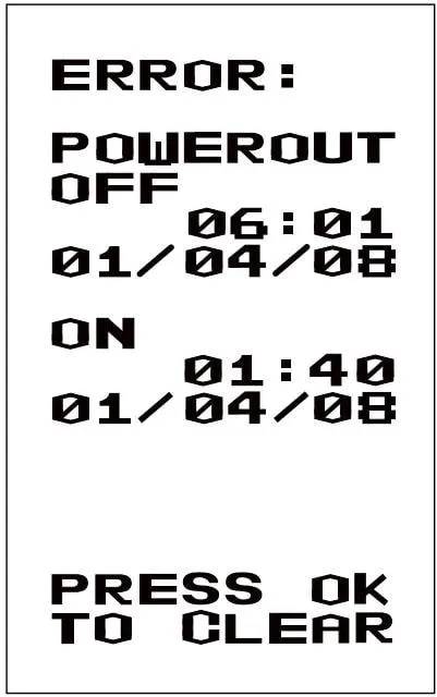 Example alarm display
2.5 Other functions
A test menu provides diagnostic functions.
BT1050 can communicate with adjacent products via infrared communication and can be configured as a master or slave. See Section 7, ‘Communications’.
2.6 Delivery, transport and storage
Factory dispatch
Before leaving the factory, the product is tested, calibrated and inspected to ensure correct operation.
Receipt
At delivery, each carton should be inspected for external damage. Any visible damage must be recorded immediately on the delivery note. Carefully open the carton and check the product for damage. If there is any damage or shortage, notify Spirax Sarco immediately and provide details. Also notify the carrier of the damage and ask them to inspect the damaged product and carton on site.
Storage
If storage is required before installation, store the product at an ambient temperature of 0-65°C and 10%-90% relative humidity (non-condensing). Before installation and connection to the power supply, ensure that there is no condensation inside the product.
3. System overview
BT1050 controls the boiler bottom blowdown valve to remove deposited solids and prevent solid accumulation from damaging the boiler.
Each BT1050 has three timers. Different blowdown cycles and durations can be set. A maximum of three blowdown cycles can be scheduled per day.
The timer can also prioritise boiler blowdown. This can:
Ensure recovery time, allowing the water to cool in the blowdown vessel
Reduce heat and water waste
Select the most suitable blowdown time, such as avoiding periods of peak steam demand
When used with multiple boilers, up to nine BT1050 units can be connected together to prevent several boilers from blowing down at the same time. This helps prevent overloading the blowdown vessel and excessively high discharge water temperatures.
Input
The timer is connected directly to the power supply.
Function/output
When the programmed time is reached, the relay energises and opens the blowdown valve. The opening duration is determined by the programmed setting. The valve then remains closed until the next cycle.
If a switch box is fitted to the blowdown valve and the valve fails to open or close during the programmed time, the alarm relay is de-energised. See Commissioning, Section 6.3.9, ‘Alarm submenu’.
4. Mechanical Installation
Note: Read the safety information in Section 1 before installing this product.
The product must be installed in a suitable industrial control panel or fireproof enclosure that provides protection against impact and environmental conditions. A minimum rating of IP54 (EN60529) or Form 3, 3S, 4, 4X, 6P, and 13 (UL50/NEMA250) is required. This product meets the requirements of Clause 23.2 of UL508 and may be considered part of an industrial-application SVA fireproof enclosure.
4.1 Environmental Conditions
The product installation environment should minimise the effects of heat, vibration, and electrical interference (refer to Section 1, ‘Safety Information’).
Do not install the product outdoors unless additional weather protection is provided.
4.2 Installation on a DIN Rail
Clips and a set of self-tapping screws are supplied with the product for installation on a 35 mm DIN rail. Two sets of holes on the rear of the enclosure determine the height position.
The clip position can be adjusted. Install the clips in one set of holes and secure them using the two screws supplied. Ensure that the clips firmly grip the rail.
Note: Use only the screws supplied with the product.
4.3 Installation on a Baseplate
Drill holes in the baseplate as shown in Figure 4.
Mount the product on the baseplate using two screws, nuts, and washers through the upper and lower slots.
Note: Do not drill holes in the product enclosure or use self-tapping screws.
4.4 Installation in a Cut-out Panel
(If a bezel is used, the minimum panel thickness is 1 mm.)
Integral threaded inserts (M4×0.7) are provided at the top and bottom of the product.
Two M4×25 mm screws, fibre washers, and a bezel are supplied.
 DIN rail clip installation diagram
Note: Do not use screws longer than 25 mm to prevent electric shock.
Cut out the panel according to the dimensions in Figure 4 and drill the threaded holes as indicated.
Remove the backing from the washers and place them on the front of the product.
The bezel can be used to improve the appearance. Install it on the outside of the panel if required.
Install the product from the rear of the panel and secure it using the screws, washers (and bezel), as applicable.
Tighten the M4 screws to 1.0 - 1.2 Nm.
Note: Do not drill holes in the product or use self-tapping screws.
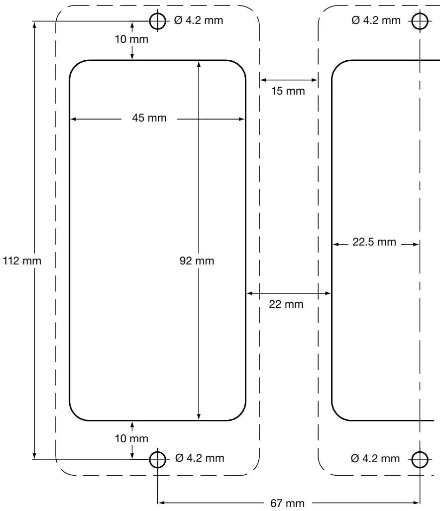 Baseplate panel cut-out dimensions
Fixed-template cut-out instructions:
- The solid lines indicate the cut-out required for the mounting panel.
- The dashed lines indicate the product outline.
- A minimum clearance of 15 mm is required between products to allow heat dissipation and cooling.
- The mounting hole dimensions are the same for panel and wall mounting.
5. Electrical Installation
Note: Read the safety information in Section 1 before installing this product.
 Electrical safety warning icon
Warning: Disconnect the power supply before touching the terminal block, as hazardous voltages may be present.
Use only the connectors supplied with the product or approved replacement parts. Using different connectors may compromise product safety and certification. Ensure that there is no condensation inside the product before installing and connecting the power supply.
5.1 General Wiring Instructions
User safety was considered in the design of the product, but the following points must be observed:
- Maintenance personnel must be suitably qualified to work with hazardous voltages.
- Ensure correct installation. Failure to follow these installation and maintenance instructions may reduce the product’s safety rating.
- The product relies on the building installation’s overcurrent protection and main isolation.
- All live conductors must be fitted with a 3 amp current-limiting protective device. If current-limiting protective devices are installed in both power supply lines, operation of one device must also trigger the other. Refer to IEC60364 (electrical installations of buildings), or follow local requirements for overcurrent protection.
- The relay circuit must be fitted with a 3 A fast-acting fuse.
- Relay contacts must use the same phase as the mains supply.
- The product is designed for Installation Category III.
- Wiring standards:
IEC60364 - Low-voltage electrical installations
EN50156 - Electrical equipment of furnaces and ancillary equipment
BS6739 - Instrumentation in process control: design, installation, practice, or the applicable local regulations.
National and local electrical codes for the United States and Canada, including the National Electrical Code (NEC) or Canadian Electrical Code (CEC). Note: Use NEC Class 1 temperature-rated values above 75 °C. If cables are exposed to higher temperatures, select a higher temperature rating.
The shields of signal cables must be connected to ensure electromagnetic compatibility.
All external circuits must meet and maintain the requirements for double protection specified in IEC 60364 or an equivalent standard.
Additional measures must be taken to prevent accessible parts, such as signal terminals, from contacting power cables if a power terminal connection becomes loose. Additional devices should be installed as close as possible to the circuit board, without applying additional force to the terminals. For example, use a cable clamp to bundle the live and neutral conductors together. If one conductor becomes loose, the other will prevent it from contacting other components.
A disconnecting device (switch or circuit breaker) must be provided in the building installation. The device must:
- Have an adequate breaking capacity;
- Be located as close as practicable to the equipment for convenient operation, and not be installed where operation is difficult;
- Disconnect all live conductor terminals;
- Be labelled as the product’s disconnecting device;
- Not impair protective earthing;
- Not be used as the main power supply;
- Comply with the requirements for disconnecting devices in IEC60947-1 and IEC60947-3;
- Refer to Section 10 - ‘Technical Information’ for terminal and cable specifications.
5.2 Mains Wiring Instructions
- Read Section 5.1 before connecting the mains supply;
- All live terminals must be fitted with fuses;
The disconnecting device complies with IEC 60917-1 and IEC60917-3. 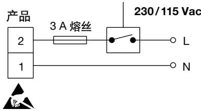 Mains supply wiring diagram
The disconnecting device complies with IEC 60947-1 and IEC60947-3. 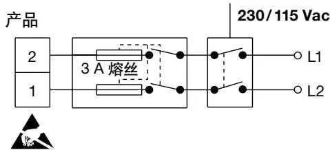 Dual-live mains supply wiring diagram
- Double or reinforced insulation must be provided between the following equipment:
- Live terminals (mains supply and relay circuits)
- Other low-voltage equipment (other components, terminals, and wires)
- The relays and switching devices shown in the wiring diagrams are in the de-energised position.
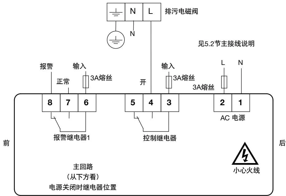 Complete main circuit wiring diagram
 Main circuit wiring diagram
5.3 Signal Wiring Instructions
If a signal cable or shield is earthed at both ends, a loop current will be generated because the earth potentials (voltages) at the two ends are different. When the wiring diagram is followed correctly, the sensor should be earthed at one end only.
The product earth is functional earth, not protective earth.
Protective earthing prevents electric shock in the event of a single fault. Functional earthing ensures normal product operation. In this product application, functional earth provides a source or sink for electrical interference. The earth terminal must be connected in accordance with the EMC directive.
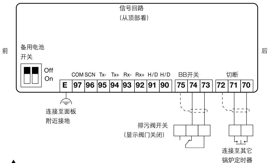 Signal circuit wiring diagram
 Signal circuit wiring illustration
Note:
E = functional earth. Connect these terminals to the local earth connection on the panel.
Switch the backup battery switch to ON to activate the battery.
5.4 EIA/TIA-485 Communications Wiring
The controller can be connected as a slave to a two-wire or four-wire EIA/TIA 485 network.
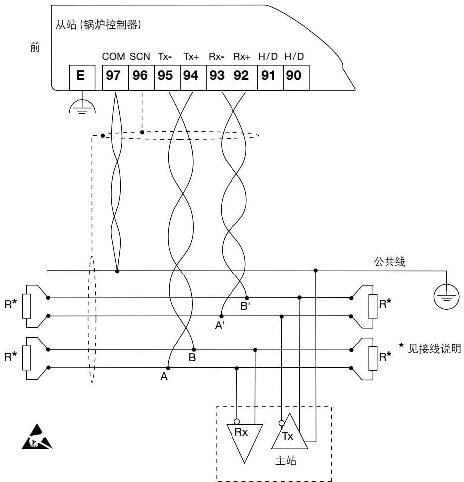 RS485 Modbus full-duplex circuit wiring diagram
EIA/TIA-485 communications wiring instructions:
EIA/TIA-485 uses the notation (A = Tx -, B = Tx + and A^′ = Rx -, B^′ = Rx +).
The signal direction is relative to the controller acting as a Modbus slave. That is, Tx+ from the product (slave) is connected to Rx+ on the master.
If the distance is less than 1.5 m, twisted-pair cable is not required; standard shielded cable is sufficient.
The H/D (half-duplex) terminals are used to select two-wire or four-wire Modbus:
- For two-wire operation, connect terminals 90 and 91.
- For four-wire operation, do not connect terminals 90 and 91.
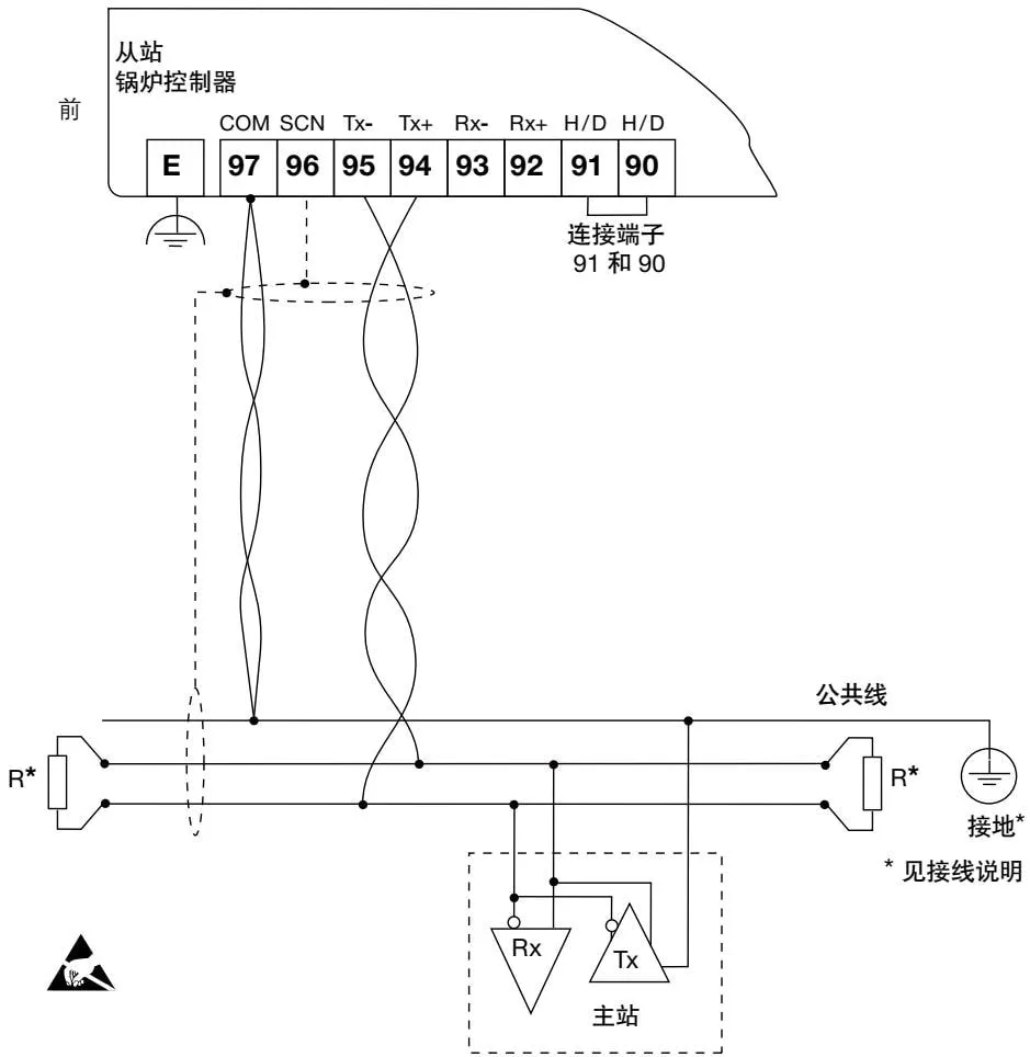 RS485 Modbus half-duplex circuit wiring diagram
EIA/TIA-485 Wiring Instructions (continued)
- The common bus conductor must be directly earthed at one point only. This point is generally located near the master.
- Termination resistors are normally installed at both ends of the bus to match the conductor resistance. A 150 Ω (0.5 W) or 120 Ω (0.25 W) resistor is typically connected in series with a 1 nF (10 V) capacitor, but the ideal method is to match the conductor resistance with the resistance of each device. When the communication distance is <300 m @ 9600 Baud, termination resistors may be omitted;
- Refer to the cable specifications in ‘Technical Information’.
6. Commissioning
Product settings are stored in non-volatile memory (flash memory). To change a parameter setting, press OK to write it to memory. For quick setup, see Section 6.2. When the main power supply is switched off, an internal battery keeps the clock running. When connecting the battery, set switch SWI (see 5.3) to the ON/OFF position.
Note: If the battery is switched off and the main power supply is then disconnected, an incorrect date and time will be displayed when the main power supply is restored. To correct this, switch on the battery and enter the correct date and time.
6.1 Overview
All commissioning is performed from the product front panel. The front panel has a display and 5 buttons - see Figure 9 and Section 2.
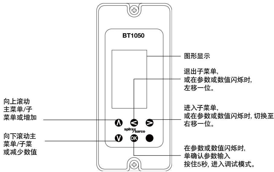 BT1050 front panel display diagram
Warning: When entering commissioning mode, the product will stop normal control operation. The control relay will stop the valve. For safety reasons, the alarm relay will remain operational. To restore normal control operation, return to the run menu.
Warning: If no button is pressed for more than 5 minutes, the unit will return to run mode and display an error. If commissioning is incomplete, the controller cannot perform control functions.
6.1.1 Entering Commissioning
In run mode, press and hold the OK button for 5 seconds to enter commissioning mode.
PASS CODE
8888
The bar graph disappears, and ‘PASS CODE’ and ‘8888’ are displayed in the lower-right corner of the screen. The flashing digit indicates the cursor position. The factory default pass code is 7452, but it can be changed in commissioning mode. Use A and V to increase or decrease the value of the flashing digit, and use the < and > buttons to move the cursor. Press and hold OK to confirm the pass code. If an incorrect pass code is entered, the display automatically returns to run mode.
6.1.2 Commissioning Mode Guide
After entering the correct pass code, the following is displayed:
MODE
To exit commissioning mode at any step, press and hold to return to run mode.
Use A and V to scroll through the first-level menu.
Press ▷ to enter the next submenu level. The first-level menu remains displayed at the top of the screen, and the submenu is displayed on the next line. As you continue entering submenus, the list expands to show the menu structure.
6.1.3 Changing Settings (Parameters)
If a parameter needs to be changed in a submenu, the relevant unit (if applicable) is displayed on the next line in brackets, and the parameter itself appears in the lower-right corner. The first digit starts flashing, indicating that the parameter can be changed.
If the OK button is pressed, the displayed value is entered into memory. If the < button is pressed, the parameter remains unchanged. The submenu, parameter, and unit then disappear, and the previous menu is displayed.
Note: If an entered value is outside the parameter range, an exclamation mark (!) is displayed to the left of the parameter. The acceptable minimum or maximum parameter value is then displayed.
6.2 Commissioning - Quick Setup
This section allows the user to make the minimum settings required to operate the system.
The factory default settings can be accepted only if the original default settings have not been changed. Refer to the default settings in Section 10.10 for confirmation.
If required, settings can be configured according to individual customer/application requirements.
Warning: It is important that you comply with national/local regulations and guidance, as well as the boiler manufacturer’s recommendations. The configured parameters must enable safe boiler operation.
Quick Setup - Commissioning
For a single boiler operating from Monday to Friday, with no blowdown valve switch installed and a recovery time of 4 hours, configure the following settings.
| Parameter | Action |
| 1. Clock | |
| - Hour | |
| - Minute | Actual date and time |
| - Month | |
| - Year | |
| 2. Blowdown time | Depends on installation and water conditions; 5 seconds recommended |
| 3. Start date and time | Set the blowdown cycle (day, hour, minute) |
Test the system to ensure correct operation.
6.3 Commissioning - Full Setup
6.3.1 Main Menu Structure
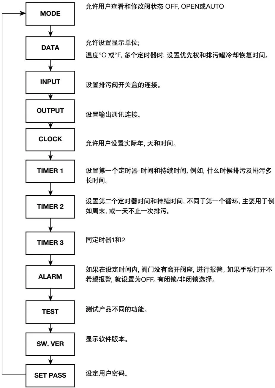 MODE main menu structure flowchart
6.3.2 Commissioning Through Submenus
An overview of the submenus and their functions is provided below, enabling the user to configure the product. Further information is provided where additional selections are available.
Select a submenu, and the adjustable parameter appears in the lower-right corner of the screen.
The current initial parameter value is stored in memory. To change a parameter, use the A and V buttons to scroll up or down through the available options. The currently saved/selected parameter flashes. To select a new parameter, press the OK button to confirm. To exit a submenu, press the < button.
6.3.3 MODE Submenu
Allows the user to switch between automatic and manual valve control.
MODE
OPEN
Entering this menu (press ▶) displays the current valve status; AUTO, OFF, and OPEN flash:
-OFF No timed blowdown
-OPEN Continuous blowdown, for example to drain the boiler
-AUTO Automatic timed blowdown
Use the A and V buttons to switch the status.
Press OK to confirm the selection.
Press the ◀ button to exit the submenu and return to run mode.
Note: AUTO is the normal setting for the blowdown valve.
Warning: During operation or commissioning, this product remains in the selected mode.
If OPEN mode is selected, the boiler may be drained.
6.3.4 DATA Submenu
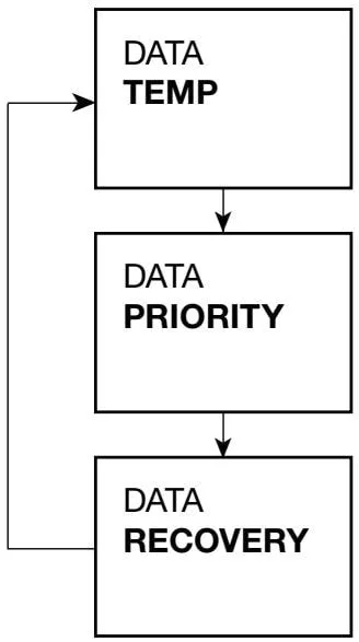 DATA submenu structure flowchart
°F or °C (default °C)
Select an option and press the OK button to confirm.
To prevent more than one boiler from blowing down simultaneously, select the timer priority. 9 is highest and 1 is lowest. If the timer is not connected to other timers, select ‘0.
Set the blowdown vessel cooling time (in hours and minutes).
Setting the recovery time to ‘zero’ clears any recovery time currently in progress.
6.3.5 INPUT Submenu
Configure the connections for the blowdown valve and burner switch.
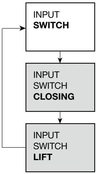 INPUT submenu structure flowchart
Blowdown valve fitted with switch - FITTED; no switch fitted - NONE.
Select the required setting.
This option is available only when FITTED is selected for the blowdown valve switch. Set the delay before an alarm signal is issued if the blowdown valve fails to close.
Warning - Maximum 5 seconds recommended.
This option is available only when FITTED is selected for the blowdown valve switch. Set the delay before an alarm signal is issued if the blowdown valve fails to open.
6.3.6 OUTPUT Submenu
Select MODBUS communication settings:
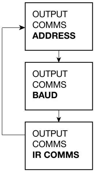 OUTPUT submenu structure flowchart
Address - Sets the MODBUS communication address. The default setting is 001, and the maximum is 247.
The baud rate sets the communication speed between the product and the polling device, in bytes per second. It can be set to 1200, 9600, or 19200; the default setting is 9600.
IR COMMS - Sets infrared communication master/slave mode.
Unless required otherwise, generally select SLAVE.
6.3.7 CLOCK Submenu
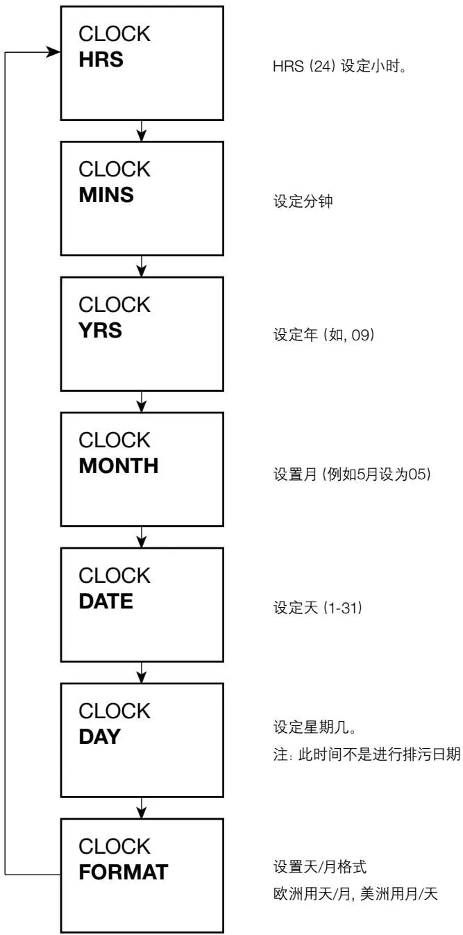 CLOCK submenu structure flowchart
6.3.8 TIMER Submenu
The timer controls the bottom blowdown interval and duration.
Parameters vary for different boiler types. Consult the boiler manufacturer, insurance company, or specialist water treatment company. Timers 1, 2, and 3 are configured in the same way, as follows:
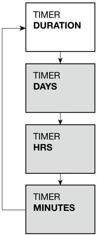 TIMER submenu structure flowchart
Set the duration for which the blowdown valve remains open.
-For blowdown time, consult the boiler manufacturer, insurance company, or specialist water treatment company. We recommend a setting of 5 seconds.
Set the days on which the blowdown cycle operates - Monday to Friday, Saturday, or Sunday. This is not displayed if the blowdown time is zero.
Set the hour at which blowdown is performed each day. This is not displayed if the blowdown time is zero.
Set the minute at which blowdown is performed each day. This is not displayed if the blowdown time is zero.
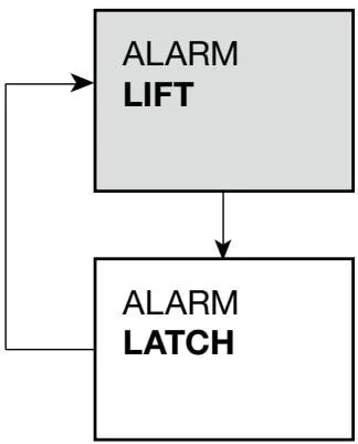 ALARM submenu structure flowchart
This option is available only when a switch is fitted to the blowdown valve. Set ON or OFF.
ON - An alarm is generated if the valve does not open within the specified time.
OFF - No alarm.
Note: If ON is selected, an alarm is generated when MODE is set to OPEN or when the valve is opened manually.
ON - The alarm is latched until commissioning mode is entered.
OFF - The alarm remains active until the condition that triggered it disappears.
6.3.9 ALARM Submenu
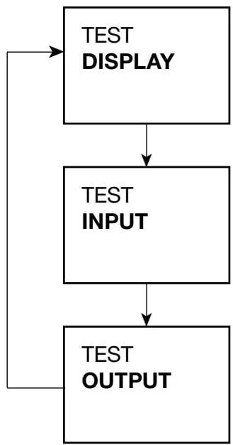 TEST submenu structure flowchart
Display test
-Black text on a white background, or white text on a black background
- The user can check for defective pixels.
Input test:
INT TEMP - Displays the maximum temperature of the internal electronic components
LINK - Detects whether another boiler is blowing down. If MDOE - OPEN is selected, ‘ON’ is displayed.
SWITCH - Detects whether the switch is open or closed
Output test:
VALVE - Manually opens or closes the valve
ALARM - Manually energizes or de-energizes the alarm relay
CANCEL - Select cancel or wait 5 minutes to return to automatic control.
6.3.10 TEST Submenu
SW VER
6.3.11 SOFTWARE VERSION Submenu
Allows the user to view the software version; refer to other documentation.
6.3.12 PASS CODE Submenu
SET PASS
Allows the default pass code to be changed, which is important for protecting parameter security.
7. Communications
7.1 Infrared (IR)
Adjacent products within a certain range can communicate via the IR bus.
This allows parameters from up to 7 products to be transmitted to a product fitted with RS485, as shown.
The product connected to the RS485 network must be installed to the left of all IR bus slave units (Figure 30), and ‘OUTPUT-COMMS’ must be selected in the ‘MASTER’ menu.
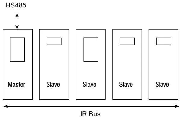 IR bus master-slave connection diagram
Two or more IR buses can share the same enclosure or DIN rail. Master 2 will ignore bus 1. See Figure 11.
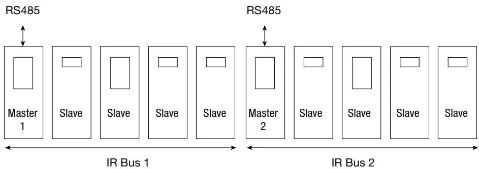 Multiple IR bus configuration diagram
If a slave unit is added to an existing IR bus, reselect ‘MASTER’ or switch the power off and then on again. Only one IR master can transmit parameters to the RS485 network. If a slave unit is connected to the RS485 network, only that unit can transmit parameters to the RS485 network.
Note: Do not obstruct infrared transmission between products.
7.2 RS485 Address
An offset is added to the register address of each device (see above), depending on its position on the IR bus. The master offset is 0, the first device to the right of the master has an offset of 100, the next device to the right has an offset of 200, and so on.
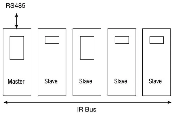 RS485 address offset mapping diagram
| IR address | 1 | 2 | 3 | 4 | 5 |
| 485 offset | 0 | 100 | 200 | 300 | 400 |
8. Maintenance
Note: Before carrying out any maintenance, read the safety information in Section 1.
8.1 Cleaning Instructions
Use a cloth dampened with water or isopropyl alcohol. The use of other cleaning materials may damage the product and invalidate the warranty.
No special servicing, preventive maintenance, or product inspection is required. In many countries, including the UK, regulations apply to boiler blowdown, particularly regarding hazardous situations where one boiler is shut down while other boilers remain in operation.
For general guidance, refer to Health and Safety Executive Guidance Note PM60.
The battery is replaceable and must be removed before disposing of the product.
The battery must not be buried or incinerated. It should be collected separately or disposed of in accordance with local or national regulations.
8.2 Battery Replacement and Disposal
Note: If the printed circuit board is completely removed, permanent damage will occur.
- Do not remove the front keyboard.
8.2.1 Cut the label along the connecting line
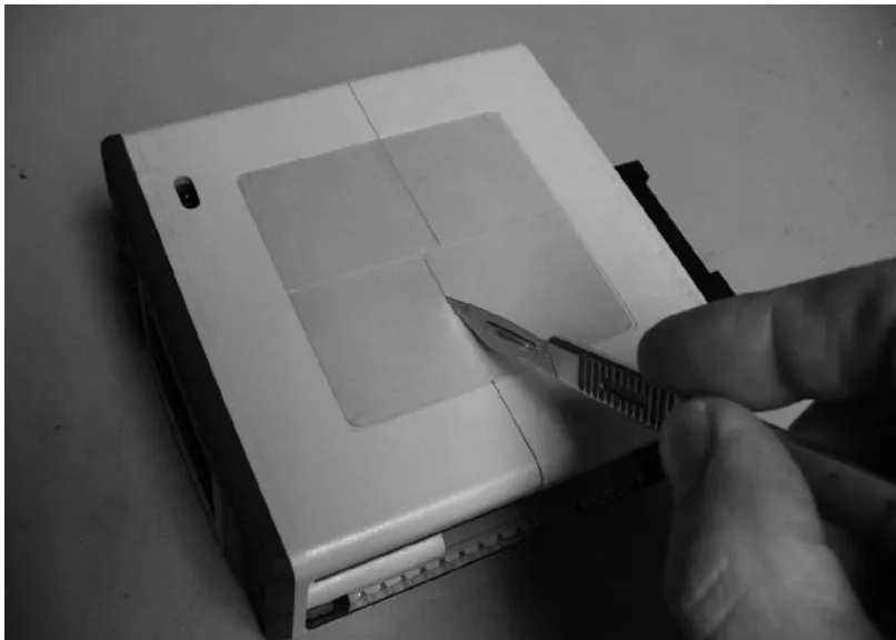 Battery replacement step 1: Cut the label along the connecting line
8.2.2 Squeeze apart the cover as indicated by the opening marks.
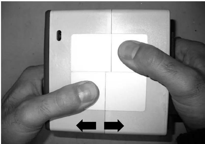 Battery replacement step 2: Squeeze apart the cover
8.2.3 Remove only the rear half of the enclosure
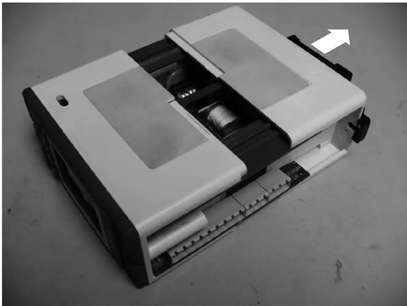 Battery replacement step 3: Remove the rear half of the enclosure
8.2.4 Remove the blue bracket
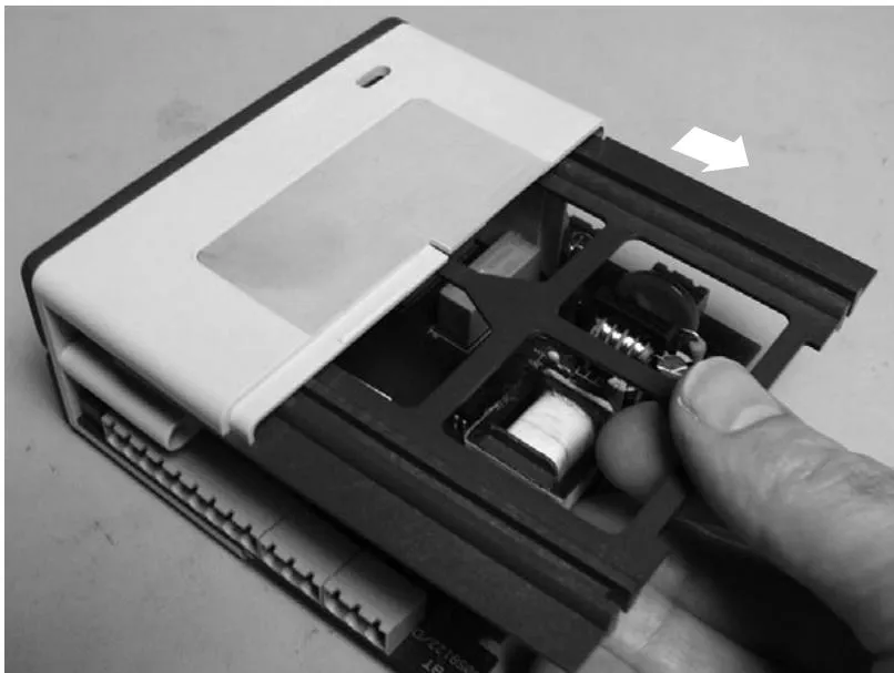 Battery replacement step 4: Remove the blue bracket
8.2.5 Note: If the printed circuit board is completely removed, permanent damage will occur. Move the PCB only far enough to access the battery cable.
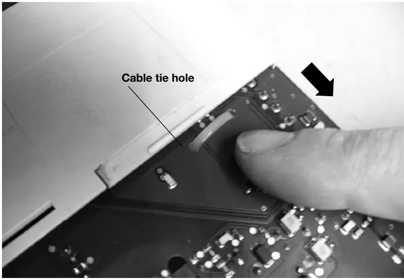 PCB cable-tie hole diagram
8.2.6 Cut the cable tie and remove the battery.
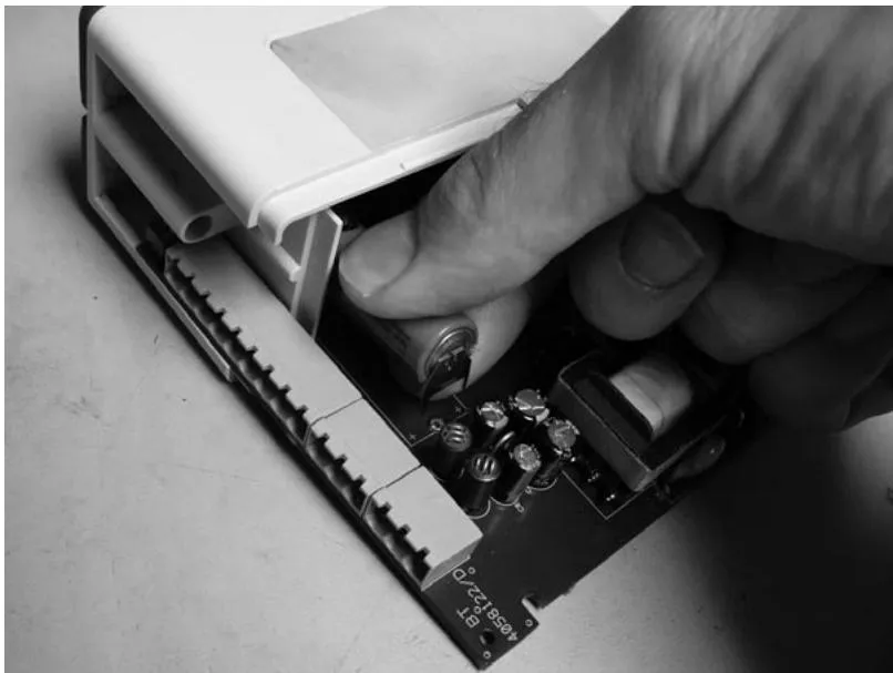 Battery replacement step 6: Cut the cable tie and remove the battery
8.2.7 Insert the new battery. Refer to Section 10.5 for the battery type. Note: The battery is polarised.
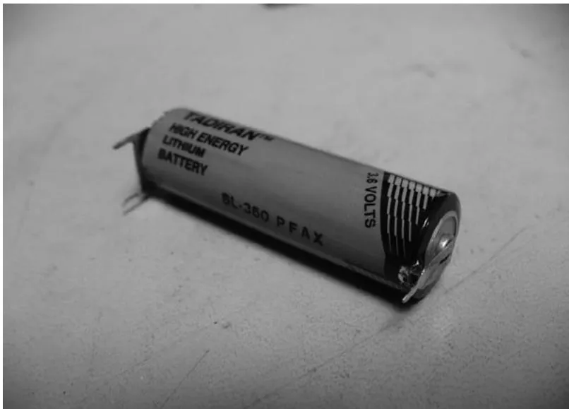 Battery type label
8.2.8 Use the holes in the PCB to secure the battery again with a cable tie.
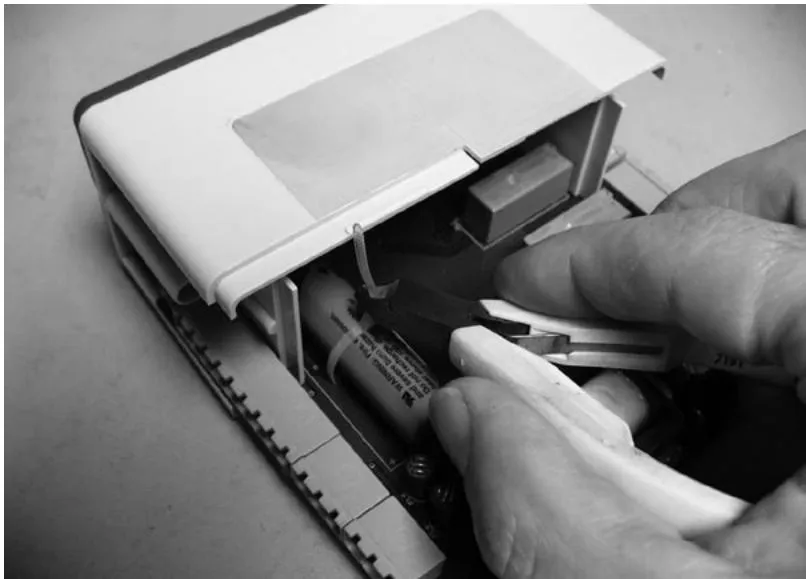 Battery replacement step 8: Secure the battery again with a cable tie
8.2.9 Reinstall the PCB in its original position and fit the blue bracket. Ensure that the arrow on the support point faces forward.
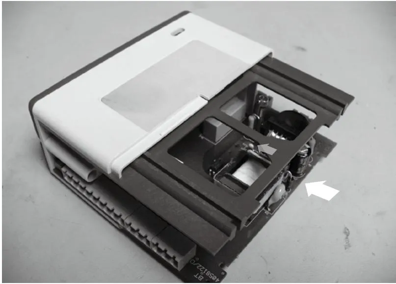 Battery replacement step 9: Install the PCB and blue bracket
8.2.10 Install the rear half of the enclosure cover.
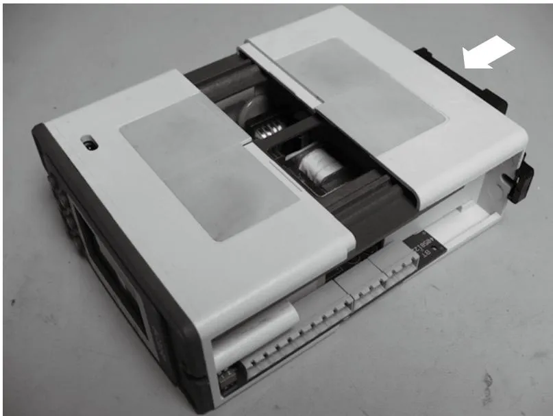 Battery replacement step 10: Install the rear half of the enclosure cover
9. Fault Diagnosis
Faults are most likely to occur during installation and commissioning. The most common fault is incorrect wiring. If the product displays an error message after power is connected, fault diagnosis is required. To simplify and assist fault diagnosis, the product includes a test menu (see Sections 6.3.10 and 2.4).
Warning:
Before starting fault diagnosis, read the safety information in Section 1 and the instructions in Section 5.1. Be aware that hazardous voltages are present. Only qualified personnel may perform fault diagnosis. Before opening the enclosure cover, the product must be disconnected from the power supply, and the cover must be fitted before power is restored. Failure to perform fault diagnosis in accordance with the procedures in this manual may reduce the safety rating.
| Symptom | Action |
| 1 Display is blank | Switch off the product power supply. Check that all wiring is correct. Check that the external fuse is serviceable and replace it if necessary. Check that the supply voltage is within the specified range. Switch on the power supply. If the symptom persists, return and replace the product. Consider the possibility that the product has been damaged by overvoltage/transients. Consider installing an additional AC line protection device between the product and the power supply. Position the protection device as close to the product as possible for adequate protection. |
 The display flashes on and off (approximately 1 second) The display flashes on and off (approximately 1 second) | 1. Switch off the product power supply. 2. Disconnect all signal cables. 3. Switch on the power supply: if the symptom persists, return the product for inspection. 4. Reconnect each signal cable in turn until the fault occurs. 5. Check and correct any incorrect wiring associated with external sensors/transmitters and modules. This indicates that the internal power supply cannot start. If the voltage cannot be generated, the power supply shuts down for approximately 1 second and then attempts to restart. If the fault persists, this cycle repeats until the fault is cleared. This is a safety feature and does not damage the product. |
 The product starts for a period of time (more than 1 minute), then shuts down. The product starts for a period of time (more than 1 minute), then shuts down. | 1. Monitor the power supply and ensure that it is continuous and within specification limits. 2. Measure the ambient temperature and ensure that it is below the specified value. 3. Check symptom 2. This indicates that the resettable thermal protection device has operated if one or more of the following occurs: - Supply voltage drops below specification. - Input voltage is below specification. - Ambient temperature is above the specified limit. - The internal power supply will shut down until the product temperature falls below 65°. This is a safety feature and does not damage the product. |
Operating Error Messages
In operating mode, any operating errors are displayed on the alarm and error screen.
| Error | Cause | Action |
| 1Power out | Power interruption during operation. | 1. Switch off the product power supply. 2. Check that all wiring is correct. 3. Check that the power supply is secure, i.e. it will not "power out". 4. Restore power. 5. Press OK to clear. |
| 2Valve failed to open | Valve failed to open. | 1. Check that the entered opening time is correct in the INPUT-LIFT menu. 2. In the test menu, check the blowdown valve switch. 3. Check the wiring between the switch and the product. 4. Check switch operation. 5. Check valve operation. 6. If necessary, inspect and replace the switch and/or valve. 7. Press OK to clear. |
| 3Valve failed to close | The blowdown valve failed to close fully. | 1. Go to the INPUT-SWITCH-CLOSING menu and check that the closing time is correct. 2. Refer to "valve failed to open". 3. Enter commissioning mode and enter the correct password. |
| 4-6Data timer X invalid | One of the three timers has lost data or contains incorrect data. Timer number is saved (X=1-3). | 1. Recommissioning is required. 2. Ensure there is no electrical interference near the product and wiring. 3. If the symptom persists, return the product. 4. Press the OK button to clear. |
| 7Data state MC overflow | The state machine is out of range; values have been saved. | 1. Refer to the action for "Data timer 'X' invalid". 2. Press the OK button to clear. |
| 8Data recovery invalid | Timer data recovery error. | 1. Refer to the action for "Data timer 'X' invalid". 2. Press the OK button to clear. |
| 9Data flags invalid | Timer register flag data has been lost or is incorrect. Timer number is saved (X=1-3). | 1. Refer to the action for "Data timer 'X' invalid". 2. Press the OK button to clear. |
| 10Data errors invalid | Timer register flag data has been lost or is incorrect. Timer number is saved (X=1-3). | 1. Refer to the action for "Data timer 'X' invalid". 2. Press the OK button to clear. |
| 11Setup menu time out | No button has been pressed for more than 5 minutes after entering commissioning mode. | 1. Re-enter commissioning mode if required. 2. Press the OK button to clear. |
| 12Alarm is latched | For safety reasons, some faults are latched. Clear the message from the fault alarm screen. | 1. Enter commissioning mode. If the password is correct, all faults can be cleared. |
10. Technical Information
10.1 Technical Assistance
Contact your local Spirax Sarco representative.
10.2 Return of Faulty Equipment
Return all product components to your local Spirax Sarco representative. Ensure that all parts are suitably packed for transport, preferably using the original carton.
Please provide the following information when returning equipment:
- Your name, company name, address and telephone number, order number, invoice, and return delivery address.
- Equipment description and serial number.
- Detailed description of the fault or repair requirements.
- If the equipment is returned under warranty, state:
Date of purchase.
Original order number.
10.3 Power Supply
| Supply voltage range | 99 to 264V AC at 50/60HZ |
| Power consumption | 230V/30mA or 115V/60mA |
10.4 Environment
| General | Indoor use only | |
| Maximum altitude | 2000 m above sea level | |
| Ambient temperature range | 0 - 55°C (32 - 131°F) | |
| Maximum relative humidity | 80% at 31°C (88°F), decreasing linearly to 50% at 40°C (104°F) | |
| Overvoltage category | Category III | |
| Pollution degree | 2 (as supplied) 3 (when installed in an enclosure) - minimum IP54 or UL50 / NEMA Type 3, 3S, 4, 4X, 6, 6P or 13. See Section 4, Mechanical Installation. | |
| Ingress protection rating (front panel only) | NEMA Type 4 only (UL certified) approved and compliant with IP65 (TRAC GLOBAL certified) | |
| Panel screw torque | 1 - 1.2 Nm | |
| LVD (Safety) | Electrical safety EN 61010-1UL61010-1, UL 508, Clause 23.2.CAN/CSA C22.2 No. 61010-1 | |
| EMC | Immunity/emissions | Suitable for heavy industrial locations |
| Enclosure | Colour | Light grey (similar to RAL7035) |
| Material | Polycarbonate | |
| Front panel | Colour | Pantone 294 (blue) |
| Material | Silicone rubber, 60shore | |
| Solder | Tin/lead (60/40%) | |
10.5 Battery (Clock Calendar)
| Manufacturer | TADIRAN |
| Manufacturer part number | SL-360/PT |
| Spirax Sarco part number | 0965057 |
| Type | AA (PCB tagged) lithium thionyl chloride (lithium content 0.65 g) |
| Voltage | 3.6 V |
| Capacity | Minimum 2.4Ah |
| Temperature range | 0 - 70°C minimum |
| Shelf life | 10 years, battery off @ Tamb: 25°C |
| Operating life | 10 years - power 35 hours / week @ Tamb: 55°C |
10.6 Cables/Data Cables and Connectors
Power and signal connectors
| Terminal | Plug-in terminal block with screw connector |
| Cable size | 0.02 mm² (24 AWG) to 2.5 mm2 (14 AWG). |
| Strip length | 5 - 6 mm |
Switch box and protective (connection) circuit
| Type | High temperature |
| Screening type | Screened |
| Number of cores | 2 |
| Gauge | 1 - 1.5 mm² (18 - 16 AWG) |
| Maximum length | 100 m |
| Recommended types | Prysmian (Pirelli) FP200, Delta Crompton Firetuf OHLS |
RS485 communication cable/wiring
| Type | EIA RS485 twisted pair |
| Screening type | Screened |
| Number of pairs | 2 or 3 |
| Cable size | 0.23 mm² (24 AWG) |
| Maximum length | 1 200 m |
| Recommended types | Alpha 6413 or 6414 |
LAN Cat 5 or Cat 5E ScTP (screened), FTP (foil), or STP (screened) cable may be used, but is limited to 600 m.
10.7 Input Technical Data
Switch box
| Maximum voltage | 32 Vdc (no load, open circuit) |
| Maximum current | 3 mAdc (short circuit) |
Protective circuit
| Maximum voltage | 32 Vdc (no load, open circuit) |
| Maximum folded voltage | 0.25 Vdc (no load, open circuit) |
| Maximum current | 1.5 mAdc |
10.8 Output Technical Data
Relays
| Contacts | 2 × single-pole changeover relays (SPCO) |
| Rated voltage (maximum) | 250 Vac |
| Resistive load | 3 amp @ 250 Vac |
| Inductive load | 1 amp @ 250 Vac |
| AC motor load | 1/4 HP (2.9 amp) @ 250 Vac 1/10 HP (3 amp) @ 120 Vac |
| Pilot duty load | C300 (2.5 amp) - control circuit/coil |
| Electrical life (operations) | 3 × 10⁵ or greater, depending on load |
| Mechanical life (operations) | 30 × 10⁶ |
RS485
| Physical layer | RS485 4-wire full duplex or 2-wire half duplex |
| Protocol layer | Modbus RTU format |
| Isolation | 60 Vac/dc |
| Receiver unit load | 1/8 (256 devices maximum) |
| Output rate | Up to 10 frames/second |
10.9 Infrared Communication
| Physical layer | IrDA |
| Baud rate | 38400 |
| Range | 10 cm |
| Operating angle | 15° |
| Eye safety information | Summary: EN 60825-12 : 2007 Laser product safety - does not exceed Class 1 emission limits (AEL) |
10.10 Default Settings
10.10.1 MODE Menu
Allows the valve to be opened or closed manually, or controlled automatically by the timer.
| Range | AUTO, OPEN, OFF |
| Default | AUTO |
10.10.2 DATA Menu
Temperature (temperature unit)
| Range | °C or °F |
| Default | °C |
Priority
| Range | 0 - 9 (highest) |
| Default | 0 (no other timers connected) |
| Resolution | 1 |
10.10.3 RECOVERY (blowdown vessel cooling time after the previous blowdown)
HRS – HOURS
| Range | 00 - 11 |
| Default | 4 |
| Resolution | 1 |
| Unit | hours (HRS) |
MINS – MINUTES
| Range | 00 - 59 |
| Default | 00 |
| Resolution | 1 |
| Unit | minutes (MIN) |
10.10.4 INPUT Menu
Switch (select FITTED if the valve is fitted with a switch)
| Range | FITTED or NONE |
| Default | NONE |
CLOSING (permitted valve closing time) - available only when a switch is fitted
| Range | 0 - 10 |
| Default | 5 |
| Resolution | 1 |
| Unit | seconds |
LIFT (permitted valve opening time) - available only when a switch is fitted
| Range | 0 - 10 |
| Default | 5 |
| Resolution | 1 |
| Unit | seconds |
10.10.5 OUTPUT Menu
COMMS-ADDRESS (MODBUS communication)
| Range | 0 - 247 |
| Default | 1 |
| Resolution | 1 |
COMMS – BAUD (MODBUS communication)
| Range | 1200, 9600, 19200 |
| Default | 9600 |
COMMS - IR (infrared communication)
| Range | Master or Slave |
| Default | Slave |
COMMS - IR (unit)
| Range | 1 - 8 |
10.10.6 CLOCK Menu
HRS-HOURS~24-hour format (clock calendar)
| Range | 00 - 23 |
| Default | 00 |
| Resolution | 1 |
| Unit | hours (HRS) |
MINS – MINUTES
| Range | 00 - 59 |
| Default | 00 |
| Resolution | 1 |
| Unit | minutes (MINS) |
YRS – YEARS
| Range | 00 - 99 (2000 - 2099) |
| Default | 00 |
| Resolution | |
| 1 | |
| Unit | years (YRS) |
MONTH
| Range | 01 - 12 |
| Default | 01 |
| Resolution | 1 |
DATE
| Range | 01 - 31 |
| Default | 01 |
| Resolution | 1 |
DAY
| Range | MON, TUE, WED, THUR, FRI, SAT, SUN |
| Default | SUN |
FORMAT
| Range | D/m or m/d |
| Default | D/m |
10.10.7 TIMER X (1-3) Menu
Duration (valve open time)
| Range | 0 - 999 |
| Default | 0 |
| Resolution | 1 |
| Unit | seconds |
Note: If the power supply is below the specified requirement, or power is interrupted during blowdown, the relay will de-energize and close the valve. If power is restored after the blowdown time has elapsed, the valve remains closed until the next blowdown cycle.
DAYS (days on which blowdown occurs) - this option is available only when the blowdown time is greater than 0
| Range | MON - FRI or SAT or SUN |
| Default | MON - FRI |
HRS (hours of the day at which blowdown occurs) - this option is available only when the blowdown time is greater than 0
| Range | 00 - 23 |
| Default | 00 |
| Resolution | 1 |
MINS (minutes of the day at which blowdown occurs) - this option is available only when the blowdown time is greater than 0
| Range | 00 - 59 |
| Default | 00 |
| Resolution | 1 |
10.10.8 ALARM Menu
LIFT (an alarm is generated if the valve plug does not lift from the seat within the specified time) - this option is available only when the blowdown time is greater than 0
| Range | ON or OFF |
| Default | ON |
LATCH (the alarm relay can be latched until commissioning mode is entered) - this option is available only when the blowdown time is greater than 0
| Range | ON or OFF |
| Default | OFF |
10.10.9 TEST Menu
DISPLAY
| Range | Black foreground on white background or white foreground on black background |
| Default | Black foreground on white background |
INPUT - INT TEMP (maximum internal temperature of the electronics)
| Range | -40 to 85°C or -40 to 185°F |
| Resolution | 1 |
| Unit | °C or °F |
INPUT - LINK (detects whether another boiler is blowing down)
| Range | ON or OFF |
INPUT - SWITCH (detects whether the switch is open or closed)
| Range | Open or Closed |
OUTPUT - VALVE (manually opens or closes the blowdown valve)
| Range | ON or OFF |
| Default | ON |
Press the OK button to energize the relay. Select Cancel, or after 5 minutes, the relay returns to automatic control.
OUTPUT - ALARM (manually opens or closes the alarm relay)
| Range | ON or OFF |
| Default | ON |
Press the OK button to energize the relay. Select Cancel, or after 5 minutes, the relay returns to automatic control.
10.10.10 SET PASS Menu
| Range | 0000 - 9999 |
| Default | 7452 |
| Resolution | 1 |
11. Appendix
Modbus Protocol Overview
Format: Byte
| Start | 1 bit |
| Data | 8 bits |
| Parity | 0 bits |
| Stop | 1 bit |
Format: Request Frame
| Address | 1 byte |
| Function Code | 1 byte |
| Starting Address | 2 bytes |
| Number of Registers | 2 bytes |
| Cyclic Redundancy Check (CRC) | 2 bytes |
| Total | 8 bytes |
Format: Response Frame
| Address | 1 byte |
| Function Code | 1 byte (or error code, see below) |
| Byte Count | 1 byte (or exception code, see below) |
| Register | 2 bytes (first bit is the most significant bit) |
| Error Check (CRC) | 2 bytes |
| Total | 7 bytes if correct (or 5 bytes if an error occurs) |
| Only function code 03, 'Read Holding Registers', is permitted. | |
Parameter and Register Data
| Register | Parameter |
| 0 | 6 - Identity Description: When the device operates as a 2R slave, if a temporary error occurs in the master-slave 2R communication, a +32768 offset is added to the slave identity value stored in the master database. |
| 1 | Timer 1 Data (Day) |
| 2 | Timer 1 Start (Time) |
| 3 | Timer 1 Duration (Seconds) |
| 4 | Timer 2 Data (Day) |
| 5 | Timer 2 Start (Time) |
| 6 | Timer 2 Duration (Seconds) |
| 7 | Timer 3 Data (Day) |
| 8 | Timer 3 Start (Time) |
| 9 | Timer 3 Duration (Seconds) |
The register data format is a 16-bit integer, with the most significant byte transmitted first.
Exception Codes
01 Illegal Function
02 Illegal Data Address
| Parameter | Byte 1 | Byte 2 | Byte 3 | Byte 4 | Byte 5 |
| Device Address | Function Code | Exception Code | CRC (LSB) | CRC (MSB) | |
| Illegal Function | XX | 83 | 01 | XX | XX |
| Illegal Data Address | XX | 83 | 02 | XX | XX |