1 Safety Information
Please comply with national or local regulations.
The product is designed and constructed to withstand stresses during use. Using the product for other purposes, or incorrectly installing it without following the installation and maintenance guide, will result in product damage and may cause personal injury or death.
The pressure equipment does not bear the CE mark and is classified as “Sound Engineering Practice” (SEP) according to Article 3, Paragraph 3 of the Pressure Equipment Directive.
Note: According to regulations, SEP products do not bear the CE mark.
Warning:
If this product is not used in the manner described in this Installation and Maintenance Instructions (IMI), the protection provided will be invalidated.
1.1 Preparation Before Use
- Check that the product is suitable for the appropriate fluid.
- Check that the materials are suitable, and the maximum and minimum values of pressure and temperature. If the maximum limit temperature of the product is lower than that of the system where it will be installed, or if product malfunction will lead to overpressure or overtemperature, ensure that the system includes safety facilities to prevent conditions exceeding the limit values.
- Determine the correct installation location and fluid direction.
- Spirax Sarco products cannot withstand external system stresses. The installation company is responsible for considering these stresses and taking sufficient measures to minimize external stresses.
- When used for steam or other high-temperature fluids, remove all connection port protection caps and the nameplate protective film before installation.
Compliance with the operating instructions and correct installation, commissioning, use, and maintenance by professionally qualified personnel is the sole guarantee of safe operation of this product (see Section 1.11). Installation must comply with piping and plant building installation guidelines and safety guidelines, using appropriate tools and equipped with necessary safety equipment.
1.2 Access
Ensure safe access. Before operating this product, a safe working platform is required; if necessary, consider arranging suitable lifting equipment.
1.3 Lighting
Ensure adequate lighting, especially when performing complex operations.
1.4 Hazardous Liquids or Gases in Piping
Consider the medium in the piping and its state of existence, including flammable substances, substances harmful to health, and substances at extreme temperatures.
1.5 Hazardous Environment Around This Product
Consider explosion hazards, oxygen deficiency (e.g., in vessels or pits), extreme temperatures, hot surfaces, fire hazards (e.g., during welding), excessive noise, mechanical movement, etc.
1.6 System
Consider the impact on the overall working system during operation. Will any operation (e.g., closing shut-off valves, electrical isolation) put other parts of the system or operators in danger.
Dangers may include isolation of venting or protection facilities, failure of controls or alarms. Ensure that shut-off valves are opened and closed slowly to avoid system vibration.
1.7 Pressure Systems
Ensure that any pressure is isolated and safely vented to atmosphere. Consider double isolation (two closures and vents), locking or tagging closed valves. Even when the pressure gauge reads zero, it cannot be confirmed that the system has been depressurized.
1.8 Temperature
After valve isolation, allow cooling to ambient temperature to avoid burns.
1.9 Tools and Required Items
Before starting work, ensure that suitable tools/available items are available. Only use Spirax Sarco replacement parts.
1.10 Protective Clothing
Consider whether to wear protective clothing to prevent injury, such as from chemicals, high/low temperatures, noise, falling objects, and situations harmful to eyes and face.
1.11 Work Qualifications
All work must be performed or supervised by qualified personnel. Installation and maintenance personnel must be trained to master the correct use of these products according to their instructions.
A formal “work qualification” system must be complied with. If no such system exists, it is recommended that the responsible person understand how to perform the work and, when necessary, arrange personnel specifically responsible for safety. If necessary, “warning notices” may be posted.
1.12 Handling
Manual handling of Spirax Sarco products may present a risk of injury. Lifting, pushing, pulling, carrying, or supporting loads with the body may cause injury, especially to the back. It is recommended to assess the hazards, considering the work, personnel, load, and working environment determined by the working environment, and use correct handling methods.
1.13 Other Hazards
During normal use, the outer surface of this product may be hot.
Many products do not have self-draining functions. Be careful when disassembling or removing the product from the installation piping (refer to “Maintenance Guide”).
1.14 Freezing
For products without self-draining functions, if used in operating conditions where the ambient temperature is below freezing, protection facilities must be provided to prevent freezing.
1.15 Safety Information - Special Instructions for Product Used in Steam Boiler Level Control and Level Limiting/Alarming
The product must be selected, installed, operated, and tested according to the following:
- Local or national standards and regulations
- Guidance manuals
- Requirements of the approving authority
- Boiler insurance
- Boiler manufacturer’s instructions
Steam boilers must be installed with two independent water level limiting/alarm systems. Level sensors must be installed in separate protection tubes/chambers, with sufficient space left between the sensor end and the bottom end.
Each sensor must be connected to an independent controller. During a low alarm, the alarm relay must cut off the boiler heating system.
The high water level alarm must be part of the water level control, or a separate system. If safety requirements are considered, a separate high water level alarm system must be installed. In this case, during a high water level alarm, the relay must simultaneously cut off the boiler feedwater and heating system. All boiler water level limiting/alarm systems require periodic functional testing.
For continuous, safe, and correct operation of water level control and limiting systems, an appropriate water treatment regime must be used. Please consult an authoritative water treatment company.
1.16 Disposal
This product is recyclable and, if properly disposed of, will not cause environmental harm.
1.17 Product Returns
When users and retailers return products to Spirax Sarco, they must comply with UK and EC health, safety, and environmental regulations. For residues or mechanical damage that cause pollution or pose hazards to health, safety, or the environment, information on the relevant hazards and the preventive measures to be taken must be provided. When providing this information, data on any substance identified as related to health and safety must be included.
2 Product Information
2.1 Overview
The Spirax Sarco LP10-4 level sensor is used with the Spirax Sarco LC1300 controller to provide level control and alarm functions for boilers, water tanks, or other vessels, and is widely applicable to conductive liquids.
2.2 Pressure/Temperature Limits
| Item | Metric | Imperial |
|---|---|---|
| Standard pressure rating | PN40 | - |
| Maximum pressure | 32 bar | 464 psi g |
| Maximum temperature | 239 °C | 462 °F |
| Ambient temperature (maximum) | 70 °C | 158 °F |
| Ambient temperature (minimum) | -20 °C | -4 °F |
2.3 Technical Parameters
| Item | Value |
|---|---|
| Protection rating | IP54 |
| Pollution degree | 3 |
| Maximum cable length (sensor to controller) | 30 m (98 ft) |
| Sensing depth (maximum) | 2095 mm (82.5”) |
| Sensing depth (minimum) | 75 mm (3”) |
| Minimum conductivity (when using LC1300 level controller) | 1 μS/cm at 25 °C (77 °F) |
2.4 LP10-4 Level Sensor Working Principle
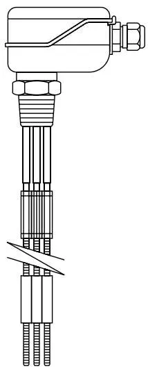
The LP10-4 has four removable probes that can be cut to the required length according to the level to be controlled. The sensor body is grounded through a 1” threaded connection, forming a ground loop with the boiler or vessel. If the sensor is used in a non-conductive water tank (such as concrete or plastic), one of the probes serves as the ground loop, or independent grounding is provided.
When the probe is immersed in conductive liquid, the current loop to ground is completed. When the level drops below the probe, the resistance to ground increases and a signal is transmitted to the controller, indicating that the level has dropped below the probe.
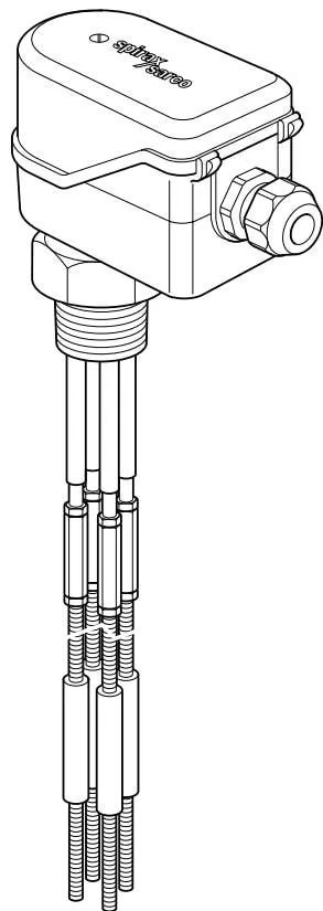
Figure 1
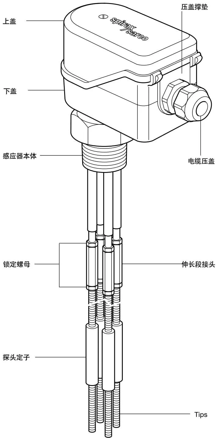
Figure 2
3 Installation
3.1 Introduction
When used for steam boilers, the sensor can be installed outside or inside the steam drum. When installed inside the steam drum, a protection tube must be used; its applicable design is described in separate documentation.
Warning
Although two sensors can be installed in one protection tube, when two low water level alarms are required in a boiler, they must be completely independent: independent sensors, independent protection tubes or protection chambers, and independent controllers must be used.
If necessary, consult the boiler manufacturer for recommendations on water level operation and alarming.
Warning
In some cases, the water level inside the boiler may not match what is displayed on the water level gauge. For this situation, refer to Spirax Sarco’s specialized documentation.
Do not install the sensor outdoors without a protective sleeve.
The sensor is designed for installation on a 1” BSP (Rp1) or 1” NPT threaded connection; the thread should be specified for new installations.
The probe stator provides lateral support and insulates the probes from each other.
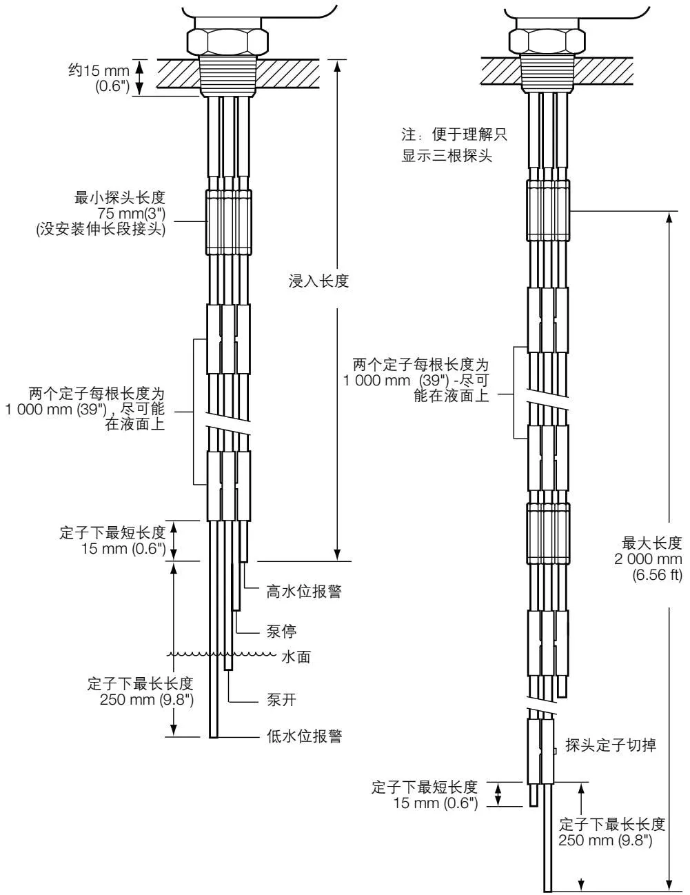
The level switch is located at the bottom end of the sensor probe, can be cut to the specified length as required, and transmits a signal to the controller during an alarm. The supplied sensor probe is a four-probe, 1000 mm (3.28 ft) long, with connection fittings, lock nuts, and two stators. If required, two probes can be connected together, with a maximum length of up to 2095 mm (6.87 ft).
Warning
The probe stator is an important part of the probe and must be installed. Failure to install the probe stator will result in short circuits between probes, or the probes will collide with the protection tube - this is a potentially dangerous condition.
3.2 Installation Steps
Warning: To avoid bending or twisting the sensor probes, when handling the sensor (especially when the length is greater than 1 m / 39”), support it along its length direction. When tightening fittings or lock nuts, do not allow the probes to rotate on the sensor body.
- Install four probes on the sensor using the supplied extension fittings and lock nuts.
- Ensure that the extension fittings are securely screwed onto the sensor probes.
- Tighten the lock nuts.
- Connect the sensor probes, ensuring they meet the required length, and install probe stators on all probes.
- Install probe stators at the probe ends.
- Remove the plastic cap or other suitable protective sleeve from the packaging and press it onto the sensor probes with the palm of your hand. After the plastic cap is installed, the probe stators can be easily positioned along the probes.
- Install the second probe stator in the same way (see Figure 3).
- If required, install a second set of extension fittings, sensor probes, and two or more stators in the same way.
- Tighten the fitting lock nuts.
Warning
Failure to tighten the lock nuts will cause the probes to become loose or fall off.
- Position the level at the first required level, for example the low water level alarm level (generally, the levels measured by a four-probe sensor may be high level, alarm, pump off, pump on, and low level alarm).
- Mark on a metal rod with a water-soluble felt pen, insert it into the boiler, and measure the depth from the top of the sensor installation fitting to the level; alternatively, read the level from the water level gauge.
- Mark the level on the sensor probes, measuring from the lower part of the sensor body, draw the cutting position on the sensor probes (score with a file or hacksaw), with an insertion length greater than 15 mm (0.6”) - recheck before cutting the probes to the required length. See Figure 3.
Repeat this step for other probes.
Sensor probes are distinguished by colored bushings:
| Brown | Probe 1 | Orange | Probe 3 |
|---|---|---|---|
| Red | Probe 2 | Yellow | Probe 4 |
Position the lowest probe stator as far above the water surface as possible. This stator will support all sensor probes, at a distance of no less than 15 mm (0.6”) from the shortest probe end. The maximum length of unsupported probes is 250 mm (9.8”). The shortest probe is 75 mm (3”) (without extension fitting installed). See Figure 3.
If fewer than all four sensor probe stators are to be installed, cut off the unused parts of the probe stators, so as to avoid the stators hitting the sensor installation interface when removing the sensor for maintenance. See Figure 4.
3.3 Install the Sensor According to the Following Steps
Ensure that all internal and external threads (1” BSP taper / 1” NPT, 41 A/F) are intact.
Wrap three turns (no more) of PTFE thread sealing tape on the sensor thread.
Warning: Do not use too much tape, and do not use adhesives such as jointing compound.
First install and hand-tighten the sensor, then tighten with a suitable wrench. Under no circumstances should a pipe wrench be used.
Do not over-tighten - the thread should be visible on the sensor.
Note: The sensor thread should not “bottom out” (i.e., the hexagonal face of the sensor housing contacts the surface of the internal threaded interface), unless the internal thread has been excessively worn or fatigued; in this case, replace or re-machine the fitting.
3.4 Subsequent Removal and Reinstallation
Warning: Before loosening or removing the sensor, ensure that the boiler or vessel has been depressurized and drained.
Use a wrench of the correct size, do not use a pipe wrench.
Check the internal and external threads for signs of damage - these may be caused by over-tightening, resulting in thread damage or cold welding effects (wear/seizure). If damaged, replace the sensor.
Figure 3: Standard installation (sensors up to 1000 mm / 39”). For installing sensors up to 2095 mm (6.87 ft), see Figure 4.
Figure 4: Installation length from 1000 mm to 2000 mm (39” to 6.56 ft), using a second section of sensor probe, extension fitting, and stators.
4 Wiring
4.1 Overview
Cable installation must comply with BS 6739 - Installation design and practice for instrumentation systems in process control - or an equivalent local standard.
4.2 Cable Specifications
Use 5-core (or 4-core and 1 ground wire) 1 mm² (18-16 AWG) high-temperature shielded cable; for the LC1300, the maximum cable length is 100 m. Both Pirelli FP200 or Delta Crompton Firetuf OHLS cables are suitable for standard sensors.
4.3 Connection
Remove the upper cover screws to access the terminal block. The LP10-4 provides 4 terminals for connection to the sensor probes, and a conductive ring terminal for connection to the sensor body ground, which can be installed on the M3 internal thread. See Figure 5.
Bolts and terminals are provided, along with colored bushings for easy identification of connecting wires. Connectors are available from Spirax Sarco as spare parts, stock number: 402480.
Note: Do not use standard terminals - the supplied terminals are high-temperature resistant.
Use a dual-purpose tool (for insulated and conductive terminals), such as RS Components or Farnell 210-511, to complete the connections.
An M20 cable gland with a diameter of 5 mm-12 mm is provided. Removing the cable gland mounting nut allows the sensor to be connected to Pg16, 1/2” BSP, 1/2” NPT, or M20 flexible conduit fittings (M20 back nut is supplied with the product).
Do not install low-voltage cables near high-voltage cables or switchgear, as this may reduce product performance or damage the product. Sensor cables must not use the same conduit/junction box as power cables or other cables.
Ensure that internal wiring or loop terminals are not compressed or damaged during installation. Before commissioning the system, remove the upper cover and check the wiring.
Removing the gland support pad facilitates operation of the cable gland:
- Remove the upper cover and take out the gland support pad, and complete wiring in the lower cover. Ensure sufficient cable or flexible conduit length so that the wiring is not taut.
- Do not over-tighten the upper cover bolts.
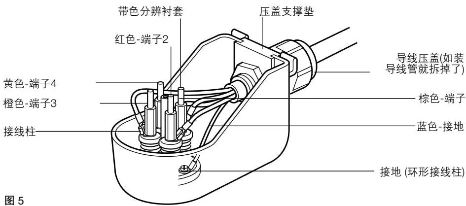
Figure 5
4.4 Shielded Cable Connection
If grounded through two different potential (voltage) points, a ground loop will be formed. If correctly installed, the sensor cable shield is grounded only through one end.
Note: Sensor grounding is functional grounding, not protective grounding.
Protective grounding provides electromagnetic oscillation protection under individual fault conditions.
Functional grounding is used for product operation. In this case, the ground terminal (boiler shell) serves as the sensor common ground, and also provides discharge for other electromagnetic interference.
- Ensure that the shield is connected to the common ground terminal of the sensor and controller.
- Ensure that the controller common ground terminal has no internal grounding (all Spirax Sarco boiler control products are internally isolated from ground).
- The controller common ground terminal must be grounded only through the sensor.
Note: Do not ground the controller’s common ground terminal locally.
This will cause a ground loop, which may reduce product performance or damage the product.
4.5 Wiring Diagram
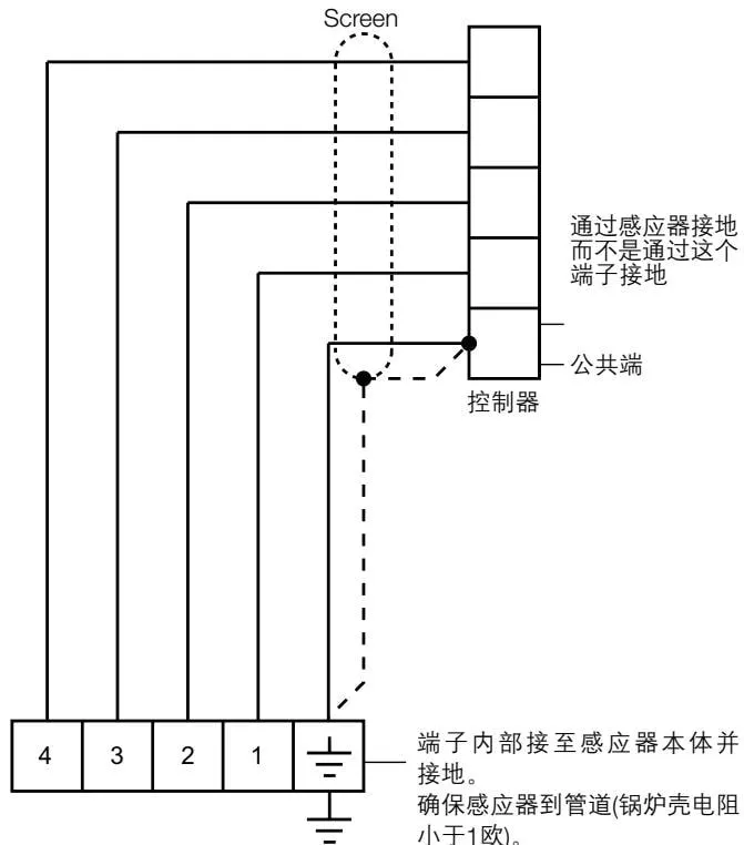
LP10-4 wiring terminals
Figure 6
5 Maintenance
This product requires no special maintenance. Steam boiler water level control systems should be tested periodically in accordance with national and local regulations; in the UK, the Health and Safety Executive will issue guidance manuals.
The UK Health and Safety Executive recommends that boiler control systems be inspected quarterly. We recommend that this interval also be observed elsewhere, unless national and local regulations provide otherwise.
When the boiler is operating well, water treatment is good, and normal inspections are performed, the sensor only requires annual inspection.
For users, a realistic inspection procedure should be developed for their respective boiler rooms by contacting the boiler inspection department.
We recommend performing the inspection according to the following steps:
- Depressurize and drain the boiler/vessel, paying attention to safety devices.
- Disconnect the controller power cable.
- Remove the sensor upper cover and check for impurities and moisture.
- Disconnect the wiring and remove the sensor.
- If required, clean the outer cover.
- Inspect the sensor.
- If required, clean the sensor probes and insulation with a cloth or brush - do not use abrasive or conductive items, such as steel wool.
Warning
- If there is scale on the sensor, there is also scale in the boiler; consult a qualified water treatment professional as soon as possible.
- Check that all extension fitting lock nuts are tightened.
- Check the sensor control wiring and power wiring.
- Check the sensor for damage.
- Reinstall and perform a comprehensive functional test of the equipment.
Available Spare Parts
| Spare part | Stock number |
|---|---|
| Connector | 4024480 |