1 Safety Information
The safe operation of the product depends on qualified operators (see Section 1.11) performing correct installation, commissioning, and maintenance in accordance with operating procedures.
Compliance with general piping and plant construction installation and safety instructions, as well as the proper use of tools and safety equipment, is mandatory.
This product is designed and manufactured to withstand certain external forces during normal use. Using this product for other purposes, or installation failure caused by not following the installation and maintenance guide, will cause damage to the product, invalidate the identification, or cause personal injury.
Additional Safety Notes: Level Control and Level Limit/Alarm Products in Steam Boilers
Products/systems must be selected, installed, operated, and tested as follows:
- Local government and national standards and regulations
- Guidance notes (in the UK, Health and Safety Executive standards BG01 and INDG436)
- Requirements of administrative authorities
- Boiler inspection departments
- Boiler manufacturer’s specifications
Two independent low water level limit/alarm devices must be installed in steam boilers.
Level sensors must be installed in protection tubes/chambers, with sufficient clearance between the protection tube and the sensor end, and grounded.
Each sensor must be connected to an independent controller. In a low water level alarm state, resetting the alarm must stop the boiler from operating.
A high water level alarm is part of the water level control, or an independent system.
For safety reasons, an independent high water level alarm system must be installed. In this case, resetting in a high water level state must cut off the boiler’s water supply and steam supply. All boiler water level limit/alarm systems require periodic functional testing.
A complete water treatment regime will ensure the continuous safe and normal operation of the control and limit/alarm systems; the above-mentioned institutions and qualified water treatment companies can be consulted.
Warning
This product complies with the Electromagnetic Compatibility Directive 2004/108/EC and all its requirements.
This product is suitable for heavy industrial environments and has undergone comprehensive and detailed EMC assessment. The BH PA420 provided in the UK has a reference number. If the following conditions occur, the product may experience interference exceeding the limit unaffected by the heavy industry:
- The product or its wiring is close to radiating sensors
- Excessive power noise occurs in the power supply circuit. If this occurs, a power supply protector (ac) needs to be installed, which can filter clutter, suppress surges, and protect against lightning strikes
- If a mobile phone or mobile radio is used within 1 m (39”) of the product or wires, it may cause interference. The actual distance will vary depending on the installation environment and the power source of the generated signal
If the product is used not in accordance with the requirements of this document, the protection provided will be weakened.
1.1 Preparation for Use
- Check that the product is suitable for the fluid whose level is to be monitored.
- Check the suitability of materials, as well as the maximum and minimum pressure and temperature. If the product’s maximum operating limit is lower than the value of the system in which the product is installed, or if product malfunction may lead to dangerous overpressure or overtemperature, ensure that the system includes safety devices to prevent such occurrences.
- Ensure correct installation position and flow direction.
- Spirax Sarco products are not designed to withstand additional stresses that may be generated by any installed system. This is something the installer needs to consider in advance and take appropriate measures to reduce; Spirax Sarco assumes no responsibility for this.
- Remove the protective sleeves of the protection fittings before installation.
1.2 Access
Ensure safety before performing any operation. If necessary, a safe working platform (with appropriate protection) is required; if necessary, arrange appropriate lifting and transmission devices.
1.3 Lighting
Ensure adequate lighting, especially in places where detailed or complex operations are performed.
1.4 Hazardous Liquids or Gases in Piping
Consider in advance the fluids that may exist or already exist in the piping; factors to consider include: whether flammable, whether hazardous to health, and temperature limits.
1.5 Hazardous Environment Around the Product
Consider: explosive environments, oxygen deficiency (e.g., in containers or cellars), hazardous gases, extreme temperatures, hot surfaces, flammable hazards (during welding), excessive noise, moving mechanical equipment.
1.6 System
Consider the impact of the operation to be performed on the entire system. Will the planned operation (e.g., closing shut-off valves, cutting off power) cause danger to other parts of the system or any personnel?
Danger may arise from the closure of discharge or protection devices, or the cancellation of control or alarms. Both opening and closing of shut-off valves must be operated slowly to avoid system oscillation.
1.7 Pressure Systems
It must be ensured that any pressure has been cut off and safely discharged to atmospheric pressure. Consider double isolation, as well as locking and tagging of closed valves. Even when the pressure gauge indicates zero, the system cannot be considered to be in a pressure-free state.
1.8 Temperature
After isolation, allow time for cooling to room temperature to avoid burns.
1.9 Tools and Spare Parts
Before starting use, ensure that suitable tools and vulnerable spare parts are available. Only use original spare parts provided by Spirax Sarco.
1.10 Protective Clothing
Consider whether you and nearby personnel need to wear protective clothing to prevent hazards, such as: chemicals, high/low temperatures, radiation, noise, falling objects, and eye and face injuries.
1.11 Work Permit
All operations must be performed or supervised by suitable personnel competent for this work. Installation and maintenance personnel must be trained on how to correctly operate this product in accordance with the installation and maintenance guide.
Comply with the formal “work permit” system, and must strictly follow the above operations. If there is no such system, it is recommended that the responsible person understand the operations being performed, and arrange assistant personnel responsible for safety matters when necessary.
If necessary, post “precautions”.
1.12 Manual Handling
Manual handling of large or heavy objects can cause danger or personal injury. Directly lifting, pulling, pushing, raising, or supporting loads with human force can cause personal injury, especially the back is more susceptible to injury. It is recommended that customers consider the task, personnel, workload, and working environment for risk assessment, and adopt appropriate handling methods according to the working environment.
1.13 Residual Hazards
Under normal circumstances, the outer surface of the product will be relatively hot.
Many products do not have a self-draining function. Extreme care should be taken when removing the product.
1.14 Freezing
When the product is exposed to environments below zero, valves without a self-draining function have a freezing hazard, and measures must be taken to protect them.
1.15 Disposal
When disposing of this product, appropriate preventive measures should be taken according to local regulations.
Unless noted in the installation and maintenance guide, this product is recyclable and, if properly disposed of, will not have a destructive effect on the ecological environment.
1.16 Product Returns
It is necessary to remind customers and stockists that, in accordance with EC health, safety, and environmental laws, when returning products to Spirax Sarco, customers must provide information about hazards, as well as the preventive measures taken when handling contaminated residues or mechanical damage - these contaminated residues and mechanical damage may cause hazards to personnel health, safety, or the environment. Relevant safety and health data sheets for any hazardous or potentially hazardous substances must be provided in writing.
2 Product Introduction
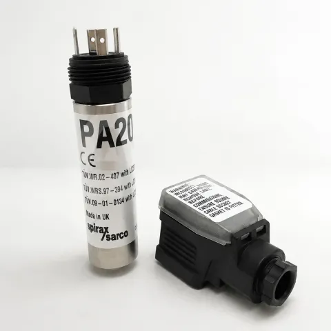
The PA20 preamplifier is used with Spirax Sarco capacitive sensors to amplify the measured capacitance and convert it into a voltage output that proportionally reflects the level.
It includes an austenitic stainless steel tube body screwed onto the top thread of the sensor, with a DIN 43650 plug with a Pg 11 cable gland (see Figure 1), or for the UL type, a 1/2” NPT cable connector with four pigtail wires (see Figure 2). The maximum ambient temperature is 70 °C (158 °F), and the minimum ambient temperature is 0 °C (32 °F). The preamplifier can be used in environments with pollution degree 3.
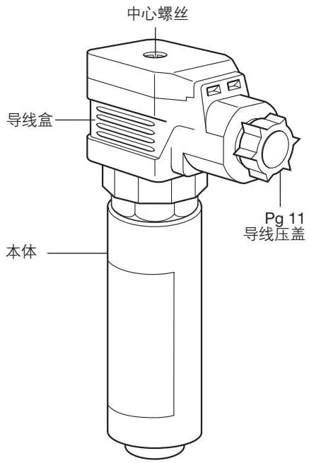
Figure 1: Standard model
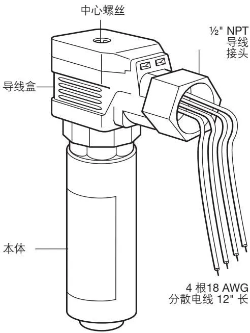
Figure 2: UL model
3 Installation
Note: The PA20 must not be installed outdoors without additional protection.
The preamplifier can be installed on the capacitive sensor before or after boiler or water tank installation. Before commissioning the controller/transmitter, allow the PA20 to stabilize at normal operating temperature for at least 15 minutes.
Install the O-ring at the bottom of the external thread of the capacitive sensor.
Note: Both the sensor and PA20 are provided with O-rings; install only one of them.
Install the preamplifier into the sensor and hand-tighten.
Warning: Over-tightening by hand or using a pipe wrench will damage the O-ring and may damage the preamplifier.
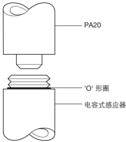
Figure 3
4 Wiring
4.1 Overview
All wiring materials and methods must comply with BS 6739 - Installation design and practice for instrumentation systems in process control - or an equivalent local standard. For installations in the United States and Canada, the wiring of the preamplifier must comply with the provisions of the local and National Electrical Code (NEC) or Canadian Electrical Code (CEC).
The voltage required by the PA20 is 15-35 Vdc (UL type 15-24 Vdc Class 2), with a maximum current of 10 mA.
The PA20 is compatible with the input voltage of all Spirax Sarco controllers/converters.
The wire is 3-core, 1 mm² (18-16 AWG) high-temperature shielded cable, with a maximum length of 100 m (328 ft). Pirelli FP 200 or Delta Crompton Firetuf OHLS are standard wires for the PA20. Ensure sufficient length to remove the preamplifier without deforming the device or wire box.
Warning:
- Do not install signal cables near high-voltage cables or switchgear.
- When routing sensor wires, they must not share the same trench or conduit as power cables.
- Anti-static measures must be taken during installation and maintenance.
4.2 Shield Connection
If the wire or shield connects two grounding points at different voltages, a ground loop is formed. If correctly following the guide, the shield of the preamplifier or controller is grounded at only one grounding point (see Figure 4).
Note: The PA20 grounding terminal is a functional grounding point, not a protective grounding point.
Protective grounding refers to providing protection against electric shock in emergency situations. This product does not require protective grounding.
Functional grounding is used for the operation of the product. In this use case, the grounding point (water tank/boiler shell) is used as the common terminal of the sensor/preamplifier, and it also serves to reduce power interference.
- Ensure that the shield is connected to the PA20 grounding terminal and the controller common terminal.
- Ensure that the controller common terminal is not internally grounded (all Spirax Sarco boiler control devices are not internally grounded).
- The controller common terminal must be grounded through the PA20.
Warning: Do not ground the common terminal at the controller end. Doing so will form a ground loop, which will weaken product function or damage the product.
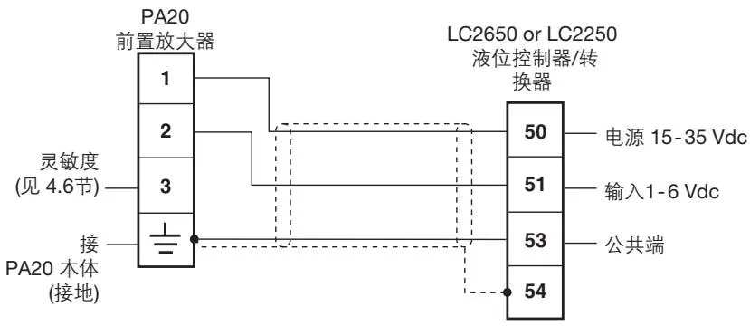
Figure 4
Warning: This terminal must not be grounded; it can only be grounded through the sensor wire.
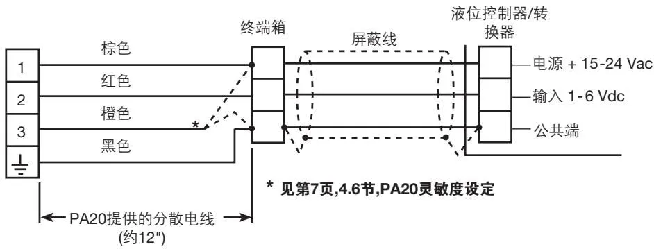
Figure 5
4.3 Junction Box
Remove the junction box and take out the center screw (see Figures 1 and 2).
Note: To provide environmental protection, the PA20 provides a square gasket between the junction box and the preamplifier connector. To ensure complete environmental protection, when reconnecting the junction box, the gasket must always be present, and all mating surfaces must be undamaged and clean.
To access the terminal block, take out the center screw and remove the hinged cover.
The terminal block of the standard PA20 can be rotated 90° for convenient wiring:
- Remove the fixing screws, hinged cover, and junction box.
- Remove the terminal block and reinstall as required.
Note: The terminal block cannot be rotated for the UL type.
4.4 Additional Wiring Information - UL Type
The preamplifier provides four 18 AWG, 12” long color-coded pigtail wires. These will be cut to equal lengths and connected to a metal terminal box. To protect the environment, there is a section of metal flexible conduit between the preamplifier and terminal box, and an electrical connection conduit is made. For this reason, there is a 1/2” NPT cable connector on the junction box. 18-16 AWG shielded cable is recommended between the terminal and controller.
Warning
- The pigtail wires provided with the sensor are rated at 221 °F (105 °C), and this temperature rating must not be exceeded.
- The flexible conduit and terminal box must not be connected to other control lines, otherwise it will cause damage or reduce the function of this product.
- The terminal block cannot be rotated for the UL type, otherwise internal wiring will be damaged.
- Special care should be taken with condensation, which will accumulate in the wire network; prevent accumulation at the sensor wire connection points and in the terminal box. Drain/vent holes must be kept clean and not covered.
- Before applying power to the PA20, disconnect the junction box connection and ensure that there is 15-35 Vdc voltage between pin 1 and the grounding terminal.
4.5 Wiring - Both Models (Figure 5)
| Terminal | Color | Description |
|---|---|---|
| Terminal 1 | Brown | Power |
| Terminal 2 | Red | Output |
| Terminal 3 | Orange | Sensitivity* |
| Grounding terminal | Black | Common |
- For the UL type, the sensitivity connection terminal is made inside the terminal box. Terminal 3 provides three different sensitivity range settings depending on the wiring method of the terminal (see Section 4.6 below).
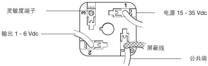
Figure 6: Top view of terminal block with cover removed (medium sensitivity)
4.6 Sensitivity Setting
- High sensitivity: immersion length below 500 mm (20”), connect terminals 1 + 3 (total sensor length below 550 mm)
- Medium sensitivity: immersion length below 1050 mm (41”), no connection
- Low sensitivity: longer immersion lengths, connect terminal 3 + grounding terminal
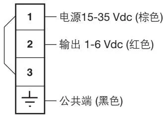
Figure 7: High sensitivity
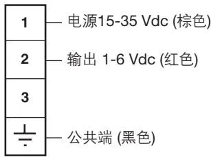
Figure 8: Medium sensitivity
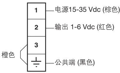
Figure 9: Low sensitivity
5 Voltage Check
Before commissioning the controller, perform voltage measurement according to the following steps:
- Close the controller switch and raise the water level to the highest point of the required measurement water level. For steam boilers, this generally refers to the uppermost end of the water level gauge.
- Measure whether the DC voltage between terminal 2 (red) of the preamplifier and the grounding terminal/common terminal (black) is between 3-6 V.
- If greater than 6 V, change the connection method of terminal 3 according to Figures 7, 8, and 9, and select the next lower sensitivity range.
- If less than 3 V, select the next higher sensitivity range according to the figure.
- Measure whether the voltage is still between 3-6 V.
- If still greater than 6 V, select the lowest sensitivity range.
The following figure (Figure 10) shows the voltage that the preamplifier should have when the sensor is inserted to a certain depth.
The exact value of the voltage depends on the installation method of the sensor and its installation length.
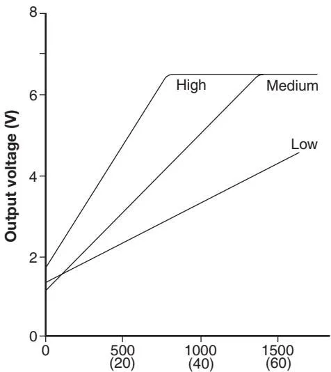
Figure 10: Sensor insertion length mm (inches)
When the sensor installation length is between 370 and 550 mm, high sensitivity must be selected. Selecting medium or low sensitivity will result in “out of range” and an alarm.
6 Maintenance
No special maintenance is required.
Boiler level control and alarms require periodic testing and inspection. For special testing of Spirax Sarco systems, see other literature.