1 Safety Information
The safe operation of this product depends on it being correctly installed, commissioned, and maintained by qualified personnel according to the operating manual (see Section 1.11).
Compliance with basic installation and safety guidelines for piping and plant construction, as well as the correct use of tools and necessary safety equipment, is also mandatory.
This product is designed and manufactured to withstand external forces during normal use.
Using it for other purposes or not installing it according to the installation and maintenance guide may cause damage to this product, invalidate the CE mark, and may also cause personal injury or death.
Other Safety Notes: Level Control and Level Limit/Alarm Products in Steam Boilers
The selection, installation, operation, and testing of products/systems must comply with:
- Local and national standards and regulations
- Guidance notes (UK Health and Safety Executive BG01 and INDG436)
- Requirements of approval authorities
- Boiler inspection institutions
- Boiler manufacturer’s specifications
Two independent low level limit/alarm systems must be installed on steam boilers. Level alarm probes must be installed in separate protection tubes/chambers, with sufficient clearance between the top and bottom.
Each probe must be connected to an independent controller. The alarm relay must disconnect boiler heating in a low level alarm state.
A high level alarm can be part of the level control, or a separate system. If considered a safety requirement, an independent high level alarm system must be installed. In this case, the relay must simultaneously disconnect the feedwater supply and boiler heating in a high level alarm state. All boiler level limiters/alarms require periodic functional testing.
A suitable water treatment regime must be used to ensure the continuous safe and correct operation of the control and limiter/alarm systems. Please consult the above institutions and qualified water treatment companies.
Warning
This product complies with the Electromagnetic Compatibility Directive 2014/30/EU and all its requirements.
If the following conditions occur, this product may be subject to interference exceeding the heavy industry immunity limit:
- The product or its wires are very close to radio transmitters
- Excessive electrical noise in the main supply circuit. If power noise may occur, protection devices (AC) should be installed on the power line. Protection devices include filtering, regulating, voltage stabilizing, and peak suppressing devices
- Mobile phones and mobile radios at a distance of about 1 m (39”) from the product or wires may cause interference to the signal. However, the actual necessary isolation distance will vary with the surrounding environment of the installation and transmitter power
If this product is not used in the manner specified in this installation and maintenance guide, the protection provided may be weakened.
1.1 Intended Use
The level preamplifier PA420 is intended for use with Spirax Sarco level controllers. If used in combination with other controllers, a safety power supply unit providing Safety Extra Low Voltage (SELV) must be used to power the controller/level preamplifier.
- Check whether the product is suitable for the intended fluid.
- Check the suitability of materials, pressure and temperature and their maximum and minimum values. If the upper limit of the product’s working range is lower than the needs of the system in which it is installed, or if the product’s fault state will cause dangerous overpressure or overtemperature, it must be ensured that the system is equipped with corresponding safety devices to prevent over-limit situations.
- Ensure correct installation and fluid flow direction.
- Spirax Sarco products cannot withstand external stresses generated by the systems in which they are installed. Installers must fully consider possible stresses and take adequate preventive measures to reduce the generation of stress.
- Remove all connection port protection caps before installation.
Correct installation, commissioning, use, and maintenance by qualified personnel (see Section 1.11) according to the operating guide is the sole guarantee of safe operation of this product. Compliance with basic installation and safety guidelines for piping and plant construction, as well as the correct use of tools and necessary safety equipment, is also mandatory.
1.2 Access
Before attempting to operate this product, ensure safe access; if necessary, also have a safe working platform (with appropriate protection). If necessary, prepare suitable lifting devices.
1.3 Lighting
Ensure adequate lighting, especially in situations requiring detailed or complex operations.
1.4 Hazardous Liquids and Gases in Piping
Consider in advance the fluids present or possibly present in the piping. Be careful of: flammable substances, health-hazardous substances, and extreme temperatures.
1.5 Hazardous Environment Where the Product is Located
Consider explosion hazards, oxygen deficiency (e.g., in tanks, pits), extreme temperatures, hot surfaces, fire hazards (e.g., during welding), excessive noise, mechanical movement, etc.
1.6 System
Consider the impact of the operation to be performed on the entire system. Will the planned operation (e.g., closing shut-off valves, cutting off power) put other parts of the system or personnel in danger?
Dangers may include the closure of ventilation equipment or protection devices, failure of control devices or alarms. Ensure that shut-off valves are opened and closed slowly to avoid shocking the system.
1.7 Pressure Systems
It must be ensured that all pressure has been isolated and safely discharged to atmospheric pressure. Consider double isolation (double block and bleed) and locking and tagging of closed valves. Even when the pressure gauge indicates zero, the system cannot be considered to be in a pressure-free state.
1.8 Temperature
After valve isolation, allow time for cooling to room temperature to avoid burns.
1.9 Tools and Consumables
Before work, ensure that suitable tools and/or consumables are available. Only use spare parts provided by Spirax Sarco.
1.10 Protective Clothing
Consider whether you or other nearby personnel should be equipped with protective clothing to prevent hazards caused by chemicals, high/low temperatures, radiation, noise, falling objects, etc., as well as eye and face injuries.
1.11 Work Permit
All work must be performed or supervised by qualified personnel.
Installation and operation personnel must receive training so that they can correctly use this product according to the installation and maintenance guide.
Where there is a formal “work permit” system, that system must be complied with. Where there is no such system, the responsible person should be clear about the nature of the work, and if necessary, arrange auxiliary personnel whose primary responsibility is to ensure safety.
If necessary, post “warning signs”.
1.12 Handling
Manual handling of large and/or heavy objects carries a risk of injury. Using bodily force to lift, push, pull, raise, or support heavy objects will cause injury, especially back injury. It is recommended to assess risks, considering workload, individual, load, and working environment, and adopt appropriate handling methods according to on-site conditions.
1.13 Residual Hazards
Under normal working conditions, the outer surface temperature of this product may be high.
Many products do not have a self-draining function. Extreme care should be taken when removing the product.
1.14 Freezing
For products without a self-draining function, if the ambient temperature may be below freezing, protection facilities must be provided to prevent freezing.
1.15 Disposal
Unless otherwise specified in this installation and maintenance guide, this product is recyclable and, if properly disposed of, will not cause environmental problems.
1.16 Product Returns
We hereby remind customers and distributors that, according to European health, safety, and environmental regulations, when returning products to Spirax Sarco, information about the health, safety, and environmental risks that may be posed by contaminated residues and mechanical damage, as well as their preventive measures, must be provided. This information must be provided in writing, including health and safety data sheets related to substances identified as hazardous or potentially hazardous.
2 Basic Product Information
Warning: During installation and maintenance, appropriate anti-static measures must be taken.
2.1 Introduction
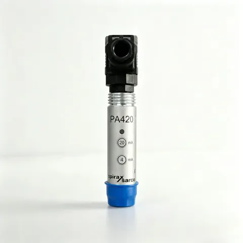
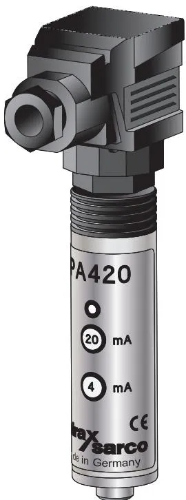
The PA420 preamplifier, used in combination with Spirax Sarco’s LP20 and LP21 capacitive level sensors, is a loop-powered transmitter. It outputs a 4-20 mA current signal proportional to the level in a water tank or boiler. This signal is compatible with Spirax Sarco and standard industrial controllers used for controlling or monitoring levels.
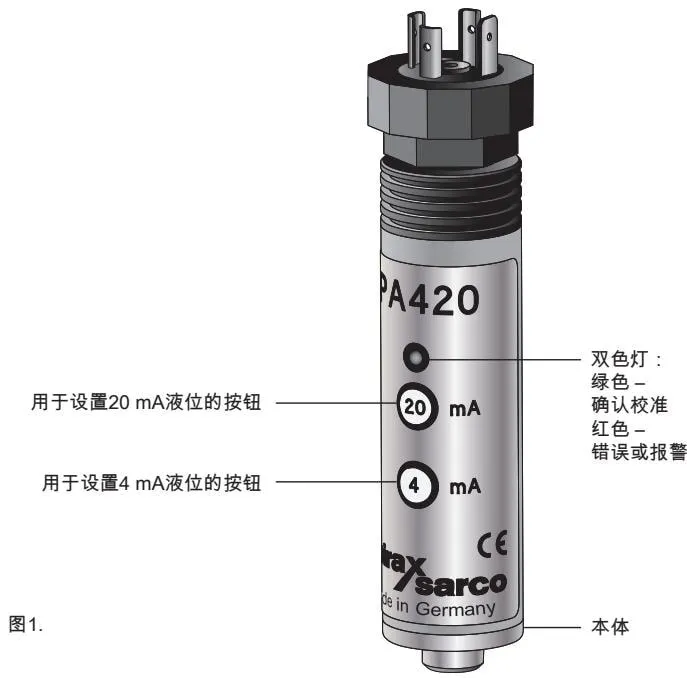
It has two buttons for commissioning and a two-color light (red and green).
It consists of a tubular austenitic stainless steel body that is fixed by threads to the top of the level probe; it also has a DIN 43650 connector with a Pg 11 cable gland (see Figure 1) - never replace the gland with anything other than Pg 11.
Certifications
- TÜV, VdTÜV-Merkblatt, Wasserstand 100
- Electromagnetic Compatibility Directive 2014/30/EU
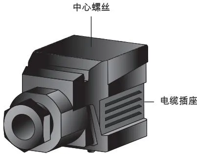
Figure 1
3 Installation
Warning:
- Do not install the PA420 outdoors without additional environmental protection devices.
- During installation, appropriate anti-static measures must be taken.
- Using a wrench will damage the O-ring and may damage the preamplifier.
The preamplifier can be installed on the capacitive probe before or after the capacitive probe is installed on the boiler or water tank. Before commissioning the controller, always allow the PA420 to stabilize at its normal operating temperature for at least 15 minutes.
Install the supplied O-ring to the bottom of the external thread of the capacitive probe.
Note: Both the probe and PA420 are equipped with an O-ring; only one of them needs to be installed.
Install the preamplifier onto the probe and tighten only by hand.
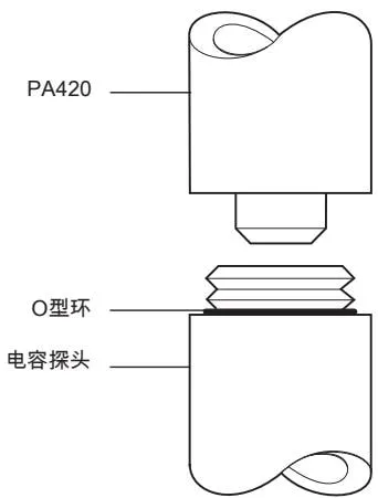
Figure 2
4 Wiring
4.1 Introduction
Cable installation must comply with BS 6739 - Instrumentation systems in process control: installation design and practice - or an equivalent local standard. When installing in the United States and Canada, the wiring of the preamplifier must comply with national and local electrical codes (NEC) or Canadian Electrical Code (CEC).
Ensure that sufficient cable length is provided to allow removal of the preamplifier, and ensure that no pressure is applied to the equipment or cable connector.
See technical specifications for cable specifications.
Note:
- Never install signal cables near high-voltage cables or switchgear.
- Probe cabling must not use the same conduit/junction box as power cables.
- During installation and maintenance, appropriate anti-static measures must be taken.
4.2 Wiring Diagram
Note: Ensure that the resistance from the probe body to the pipe/boiler shell is less than 1 Ω.
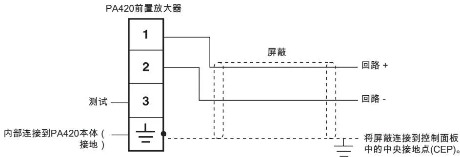
Figure 3
4.3 Cable Connector
To unplug the cable connector, remove the center screw (see Figure 1).
Note: To provide environmental protection for the PA420, a square flat washer is provided between the cable connector and the preamplifier terminal. To maintain environmental integrity, ensure that the washer is always present when reconnecting the cable connector, and that all contact surfaces are undamaged and clean.
To access the terminal module inside the cable connector, remove the center screw and pull out the hinged cover.
The terminal module on the standard PA420 can be rotated by 90° for convenient wiring: remove the fixing screws and hinged cover and take out the cable connector.
Warning
Before powering the PA420, disconnect the cable connector and ensure that the power voltage between pin 1 and pin 2 is within the specified rated range.
See Section 8 “Technical Data”: exceeding the maximum rated voltage will damage the PA420.
5 Commissioning
5.1 Level Calibration
The PA420 can be configured to output various levels between 4 mA and 20 mA. It can output 20 mA at high level and 4 mA at low level; alternatively, it can output 4 mA at high level and 20 mA at low level. Commissioning is performed using two buttons and a two-color light.
For minimum/maximum calibration range, see Section 8.
To configure the level:
Step 1: Adjust the level to the desired 4 mA or 20 mA level.
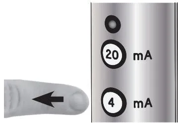
Step 2: Press and hold the 4 mA or 20 mA button for three seconds.
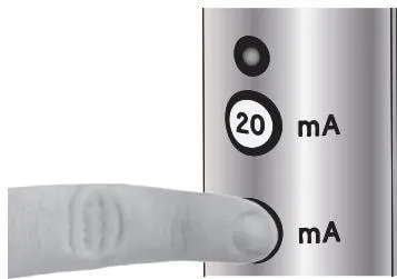
Step 3: The two-color light will flash green once.
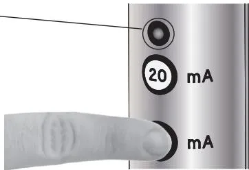
Step 4: Release the button (you will have two seconds to do this).
Step 5: The two-color light will flash green again to confirm that the level has been saved in memory.
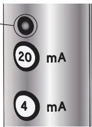
Step 6: Repeat the above operations to configure the second level.
Note: If the button is pressed or released for too short a time, the LED will flash red and will not be saved.
Figure 4 gives an example of how to commission the PA420 (level gauge).
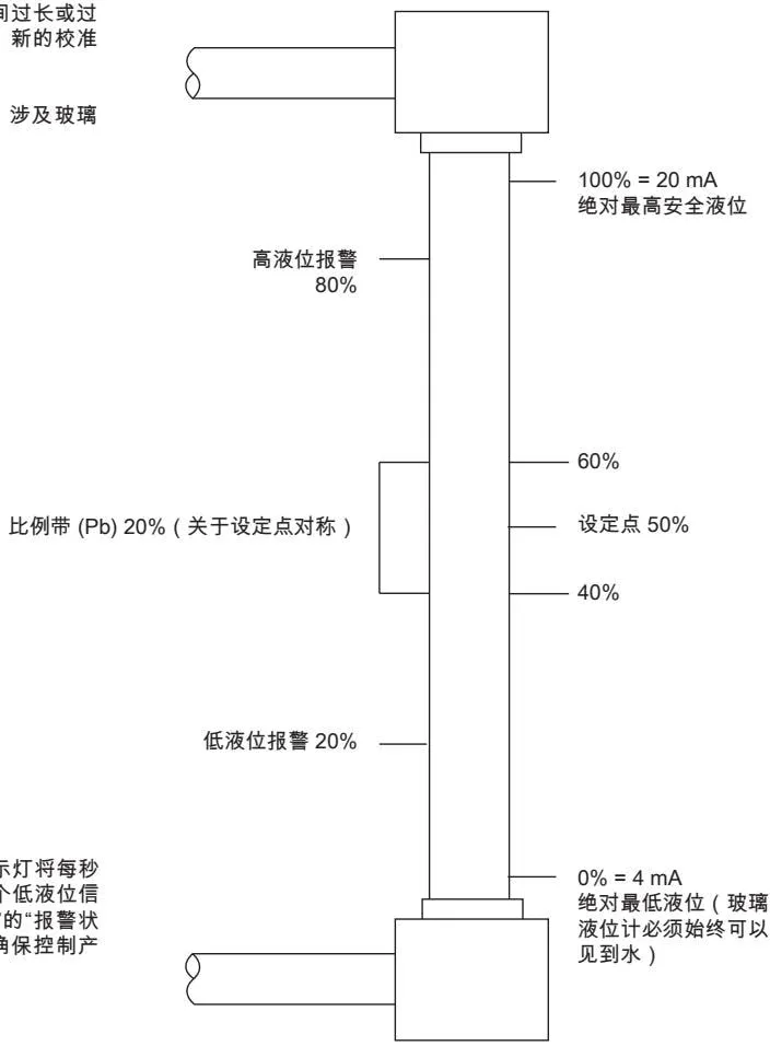
Figure 4
Warning: If a fault is detected, the indicator light flashes red once and an alarm signal will be output. See Section 8 “Technical Data” and Section 7 “Fault Finding”. Ensure that the product is configured to safely shut down the system.
6 Maintenance
Warning: During maintenance, appropriate anti-static measures must be taken.
Probe body cleaning instructions: Use a cloth dampened with tap water/deionized water or isopropyl alcohol. Using other cleaning materials may damage the product and void the warranty.
Boiler level controllers require periodic testing and inspection. For specific testing instructions for Spirax Sarco systems, see separate literature.
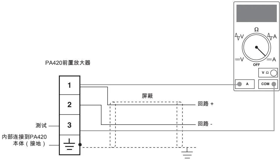
Figure 5: Measuring loop current (note that you do not need to disconnect the installation wiring)
7 Fault Finding
Warning: Before starting fault finding, please read Section 1 “Safety Information”.
The most likely time for faults to occur is during installation and commissioning.
7.1 General Faults
Symptom 1: No output current
Description: No signal - there is not enough voltage to power the product, or the product is damaged. If the fault is eliminated, the product may recover.
Action:
- Check whether the ambient temperature is within the specification range (see Section 8.2).
- Unplug the wiring port.
- Check that all wiring is correct (see Section 4).
- Check that the wiring is firm.
- Check the voltage between terminal 1 and terminal 2, and ensure it is within the specification range (see Section 8.3).
- Check the polarity of the power supply.
- Reinsert the wiring port.
- Check whether the loop current is within the specification range (see Figure 5).
- Check that the probe wiring shield is correctly connected (see Figure 3).
- Check whether the probe wires are adjacent to other cables that may interfere with the product (e.g., power cables).
- Check whether the product is located next to radio transmitting equipment.
7.2 System Alarm
When an alarm occurs, the indicator light will flash red, and the current output will be set to the alarm state. See the “Technical Data” section. To help diagnosis, the indicator light flashes continuously with pauses in between. Once the fault is corrected, the alarm can be cleared by restarting the product.
Symptom 1: Indicator light repeatedly flashes red and alarm output (see Section 8 “Technical Data - Alarm State”)
Description: Program integrity - the product program is corrupted.
Action:
- Please send the product back to your local Spirax Sarco representative.
- Before installing a replacement product, follow the actions in Section 7.1 “General Faults”.
Symptom 2: Indicator light repeatedly flashes red 2 times, alarm output
Description: Level input too low - the measured level signal from the probe is too low.
Action:
- Check the probe installation.
- Check the connection between the probe and the vessel.
- Check the connection between the probe and the preamplifier.
- Before installing a replacement product, follow the actions in Section 7.1 “General Faults”.
Symptom 3: Indicator light repeatedly flashes red 3 times, alarm output
Description: Level input too high - the measured level signal from the probe is too high.
Action:
- Check the probe installation.
- Check the distance between the probe and any metal parts.
- Check the connection between the probe and the preamplifier.
- Confirm whether the insulation layer on the probe is damaged.
- Before installing a replacement product, follow the actions in Section 7.1 “General Faults”.
7.3 System Error
When an error occurs, the indicator light will flash red. To help diagnosis, the indicator light will flash continuously with pauses in between. The error can be cleared by pressing one of the buttons. The product will continue to output current proportional to the level, and the current parameters are saved in memory.
Symptom 1: Red light flashes once
Description: Button pressed for not long enough - during commissioning, the button was pressed for not long enough, and the level input was not saved in memory.
Action:
- Repeat the commissioning procedure in Section 5.
- Please follow the actions in Section 7.1 “General Faults”.
Symptom 2: Red light repeatedly flashes 2 times
Description: Button pressed for too long - during commissioning, the button was pressed for too long, and the level input was not saved in memory.
Action:
- Repeat the commissioning procedure in Section 5.
- Please follow the actions in Section 7.1 “General Faults”.
Symptom 3: Red light repeatedly flashes 3 times
Description: Both buttons pressed - if both buttons are pressed simultaneously, this product will ignore these buttons, and the level input will not be saved in memory.
Action:
- Check whether the buttons are damaged.
- Check around the product to ensure nothing is pressing the buttons.
- Please follow the actions in Section 7.1 “General Faults”.
Symptom 4: Red light repeatedly flashes 4 times
Description: Commissioning level input out of range - during commissioning, the level calibration points are too close together, and the level input was not saved in memory.
Action:
- Repeat the commissioning procedure in Section 5, ensuring that the minimum distance between the two calibration points is maintained. See Section 8 “Technical Data”.
Symptom 5: Red light repeatedly flashes 5 times
Description: Memory content conflict - during commissioning, the product attempted to save the level signal to memory. However, an unexpected value was read back.
Action:
- Please follow the actions in Section 7.1 “General Faults”.
- Repeat the commissioning procedure in Section 5.
Symptom 6: Red light repeatedly flashes 6 times
Description: Watchdog timeout - the internal microcontroller has briefly stopped and automatically recovered.
Action:
- Please follow the actions in Section 7.1 “General Faults”.
- Monitor, data acquisition, and record the power supply voltage over a period of time.
If the problem persists, please contact your local Spirax Sarco representative.
8 Technical Data
8.1 Limiting Conditions
| Item | Value |
|---|---|
| Ambient temperature range | 0 - 70 °C (32 - 158 °F) |
| Pollution degree | 3 |
| Water conductivity | 5 μS/cm or 5 ppm |
| Maximum cable length | 100 m (328 ft), shielded (see controller installation and maintenance guide) |
| Wire cross-section | 0.5 - 1.5 mm² (20 - 16 AWG) |
| Recommended cable | 2-core shielded cable, minimum 0.5 mm² (AWG20). See controller installation and maintenance guide |
| Protection rating | IP54 |
8.2 Technical Data
| Item | Value |
|---|---|
| Voltage drop (across device) | 9 - 26.4 Vdc |
| Loop current | 4 - 20 mA |
| Alarm state (high level = 20 mA, low level = 4 mA) | 3.8 mA |
| Alarm state (high level = 4 mA, low level = 20 mA) | 22 mA |
| Maximum load | 500 Ω |
| Linearity | 2% FSD |
| Insulation | 100 Vdc (capacitive) |
| Calibration level (minimum) | 0 mm |
| Calibration level (maximum) | 1500 mm |
| Calibration range (minimum) | 50 mm |
| Calibration range (maximum) | 1500 mm |
| Resolution | 1 mm |
8.3 Certifications
- TÜV, VdTÜV-Merkblatt, Wasserstand 100 - 2017
- Electromagnetic Compatibility Directive 2014/30/EU
9 Technical Support
Contact your local Spirax Sarco representative.
Returning Faulty Equipment
Please send the entire equipment back to your local Spirax Sarco representative. Please ensure that the entire equipment is packaged for transport (preferably in the original packaging).
The following information is required for equipment returns:
- Your name/company name/address and telephone number/order number and invoice and return shipping address.
- Description and serial number of the returned equipment.
- Complete description of the fault or required repair.
- If it is an equipment return within the warranty period, please indicate: a. Date of purchase. b. Original order number.
Spirax Sarco Ltd Runnings Road Cheltenham GL51 9NQ United Kingdom