

- Safety Information
- Product Information
- Installation
- Commissioning
- Spare Parts and Maintenance
1. Safety Information
Safe operation of this product can only be guaranteed if it is properly installed, commissioned, used and maintained by qualified personnel (see Section 1.12 of this document) in accordance with the operating instructions. General installation and safety instructions for pipeline and plant construction must also be observed, together with the correct use of tools and safety equipment.
1.1 Intended Use
Refer to the Installation and Maintenance Instructions, product markings and Technical Information Sheet to check that the product is suitable for the intended use/application. This product complies with the requirements of the European Pressure Equipment Directive 2014/68/EU and falls within the “SEP” category.
It should be noted that, under the Directive, products in this category must not bear the CE mark.
i) This product has been specifically designed for use with steam, air or condensate/water in Group 2 of the above Pressure Equipment Directive. Use of the product with other fluids may be possible, but if this is contemplated, Spirax Sarco should be contacted to confirm the suitability of the product for the application being considered.
ii) Check the suitability of the material, pressure and temperature limits, including their maximum and minimum values. If the maximum operating limits of the product are lower than those of the system in which it is installed, or if product failure could result in dangerous overpressure or overtemperature, ensure that a safety device is included in the system to prevent such conditions.
iii) Determine the correct installation position and fluid flow direction.
iv) Spirax Sarco products are not intended to withstand external stresses that may be imposed by the system in which they are installed. It is the responsibility of the installer to consider these stresses and take adequate precautions to minimise them.
v) Remove protective covers from all connections and protective film from all nameplates, where applicable, before installation in steam or other high-temperature applications.
1.2 Access
Ensure safe access and, if necessary, provide a safe working platform with suitable guarding. Arrange suitable lifting equipment if required.
1.3 Lighting
Ensure adequate lighting, particularly where detailed or complex work is required.
1.4 Hazardous Liquids or Gases in the Pipeline
Consider what is in the pipeline or what may have been in it previously.
Consider: flammable materials, substances hazardous to health and extreme temperatures.
1.5 Hazardous Environment Around the Product
Consider: explosive areas, oxygen-deficient atmospheres such as tanks and pits, hazardous gases, extreme temperatures, hot surfaces, fire hazards such as during welding, excessive noise and moving machinery.
1.6 The System
Consider the effect of the proposed work on the complete system. Could any proposed action, such as closing isolation valves or electrical isolation, put another part of the system or any personnel at risk?
Hazards may include isolating vents or protective devices, or rendering controls or alarms ineffective. Ensure that isolation valves are opened and closed gradually to avoid system shock.
1.7 Pressure Systems
Before carrying out any maintenance on the pipe connector, ensure that all pressure has been isolated and safely vented to atmospheric pressure before undertaking any maintenance work.
1.8 Temperature
Allow time for the temperature to return to normal after isolation to avoid the risk of burns, and consider whether protective clothing, including safety glasses, is required.
1.9 Tools and Consumables
Before starting work, ensure that suitable tools and/or consumables are available. Use only genuine Spirax Sarco replacement parts.
1.10 Protective Clothing
Consider whether you and/or others in the vicinity require protective clothing to protect against, for example, chemicals, high/low temperatures, radiation, noise, falling objects, and hazards to the eyes and face.
1.11 Permits to Work
All work must be carried out by suitably competent personnel or under their supervision. Installation and operating personnel should be trained in the correct use of the product in accordance with the Installation and Maintenance Instructions.
Where a formal “permit to work” system is in force, it must be complied with. Where there is no such system, it is recommended that a responsible person be aware of the work in progress and, where necessary, arrange for an assistant whose primary responsibility is safety.
Post “warning notices” if necessary.
1.12 Handling
Manual handling of large and/or heavy products may present a risk of injury. Lifting, pushing, pulling, carrying or supporting a load using physical force can cause injury, particularly to the back. It is recommended that you assess the risks, taking into account the task, the individual, the load and the working environment, and use an appropriate handling method for the specific circumstances of the work being undertaken.
1.13 Residual Hazards
Under normal operating conditions, the external surface of the product may be very hot. When used at maximum permitted operating conditions, the surface temperature may exceed 425 °C (797 °F). Many products are not self-draining. Take particular care when dismantling or removing the product from an installation (refer to the “Maintenance Instructions”).
1.14 Freezing
Provision must be made to protect products that are not self-draining against frost damage when exposed to environments below freezing point.
1.15 Disposal
Unless otherwise stated in the Installation and Maintenance Instructions, this product is recyclable and no ecological hazard is anticipated with its disposal, provided due care is taken.
This product can be safely recycled and/or disposed of provided due care is taken. Always comply with local recycling and disposal regulations.
1.16 Returning Products
Customers and distributors are reminded that, under EC health, safety and environmental law, when returning products to Spirax Sarco they must provide information on any hazards and the precautions to be taken due to contamination residues or mechanical damage that may present a health, safety or environmental risk. This information must be provided in writing, including Health and Safety Data Sheets relating to any substances identified as hazardous or potentially hazardous.
2. Product Information
2.1 Description
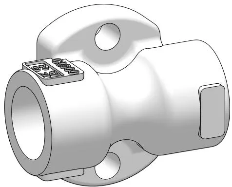
The PC10HP pipe connector is designed for use with the universal connector steam traps listed above, operating up to the maximum pressure/temperature limits of the selected steam trap. The connector can be installed in any vertical or horizontal pipeline, and the steam trap can be rotated through 360° to ensure correct orientation during operation.
The principle is that the pipe connector can be fitted into the pipeline without installing the steam trap, which is subsequently connected using only two bolts. The steam trap can be removed/replaced simply and quickly to minimise system downtime and reduce maintenance resources.
Standards
This product fully complies with the requirements of the European Pressure Equipment Directive 2014/68/EU.
Certification
This product is available with EN 10204 3.1 certification.
Note: All certification/inspection requirements must be stated at the time of order.
Note: For further information, see Technical Information Sheet TI-P128-10.
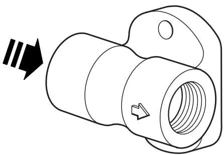
Figure 1 PC10HP is designed for use with the steam trap options listed in the right-hand column.
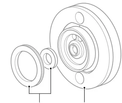
Universal steam trap gaskets are supplied with the steam trap.
Steam Trap Options
UBP32
UBP32M
UTD26
UTDS46M
UIB30
UIB45
UFT32
UFT14HC
USM21
USM32
2.2 Sizes and Pipe Connections
Condensate inlet and outlet: DN15, DN20 and DN25.
1/2”, 3/4” and 1” threaded connections: BSP T Rp (ISO 7-1) or NPT.
Socket weld ends to ASME B 16.11/BS 3799 Class 3000.
Flanged connections are also available on request. Contact Spirax Sarco for further details.
2.3 Kv Values
| Size | DN15 | DN20 | DN25 |
| Kv | 1.1 | 1.1 | 1.1 |
Conversion formulae:
Cv (UK) = Kv × 0.963
Cv (US) = Kv × 1.156
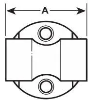
2.4 Dimensions/Weights (Approximate) in mm and kg
| Size | A | Weight |
| 1/2" | 61.5 | 0.6 |
| 3/4" | 73.5 | 0.7 |
| 1" | 90.0 | 0.7 |
2.5 Pressure/Temperature Limits (ISO 6552)
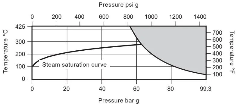
The product must not be used in this region.
Note: - If flanged connections are fitted, they will limit the maximum design conditions of the pipe connector.
- The maximum operating limits of the complete assembly will be determined by the selected steam trap. Refer to the relevant steam trap Technical Information Sheet for its maximum pressure/temperature limits.
| Body design conditions | ASME Class 600 | ||
| PMA | Maximum allowable pressure | 99.3 bar g @ 38 °C | (1440 psi g @ 100 °F) |
| TMA | Maximum allowable temperature | 425 °C @ 56 bar g | (797 °F @ 812 psi g) |
| Minimum allowable temperature | 0 °C | (32 °F) | |
| PMO | Maximum operating pressure for saturated steam service | 64 bar g @ 281 °C | (928 psi g @ 538 °F) |
| TMO | Maximum operating temperature | 425 °C @ 56 bar g | (797 °F @ 812 psi g) |
| Minimum operating temperature. Note: For lower operating temperatures, contact Spirax Sarco. | 0 °C | (32 °F) | |
| PMOB | Maximum operating back pressure must not exceed 80% of the upstream pressure. | ||
| The product is safe for use under full vacuum conditions. | |||
| Maximum cold hydraulic test pressure | 149 bar g | (2161 psi g) | |
3. Installation
Note: Before carrying out any installation, observe the “Safety information” in Section 1.
To ensure that the rotary connector steam trap operates correctly and effectively removes condensate, several conditions must be met. Refer to the installation and maintenance instructions, product markings and Technical Information sheet to check that the product is suitable for the intended installation:
3.1 Check the materials and maximum pressure/temperature values. If the maximum operating limits of the product are lower than those of the system in which it is installed, ensure that a safety device is included in the system to prevent overpressure.
3.2 The correct steam trap and end connections must be selected to meet the system design conditions.
3.3 The steam trap connector bolts are supplied with the selected steam trap.
3.4 The connection between PC10HP and the steam trap is sealed with a high-integrity spiral-wound gasket. During installation, the gasket faces must be protected from damage to the steam trap gasket face caused by welding spatter, impact or similar hazards. Therefore, particular care is required when installing PC10HP in the pipeline. It is recommended that the steam trap be installed as soon as PC10HP has been installed in the pipeline. Alternatively, the steam trap may be connected to PC10HP before installation.
3.5 Determine the correct installation position and fluid flow direction. PC10HP must be installed in the direction indicated by the arrow. The flow direction may be horizontal (in either direction), vertical or inclined. The flow direction is clearly marked on the steam trap body or pipe connector.
Note: Unless otherwise stated in the specific installation and maintenance instructions supplied with the product, the connection face of the selected universal connector steam trap must always be in a vertical plane.
3.6 Before installation in steam or other high-temperature applications, remove the protective covers from all connections, where applicable.
3.7 Suitable isolation valves must be installed to enable safe maintenance and replacement of the steam trap. When the steam trap discharges into a closed return system, a check valve should be installed downstream to prevent backflow.
3.8 Always open the isolation valves slowly until normal operating conditions are reached - this will prevent system shock. Check for leaks and correct operation.
3.9 Always ensure that the correct tools, safety procedures and protective equipment are used.
3.10 When installing socket-weld versions, welding must be carried out using a qualified welding procedure in accordance with recognized standards.
3.11 Pipe welding for socket-weld versions
It is difficult to provide a general welding procedure covering the requirements of different national and international standards and codes - particularly in relation to the welding process, welding conditions (number of passes, welding consumable size, current, voltage and polarity), welding consumable storage, and welding consumable manufacturer/model, as there are many applicable welding consumable suppliers.
Welding recommendations based on British Standards are available. Please contact Spirax Sarco to discuss your welding requirements. Welding may be carried out in accordance with the applicable ASME IX or BS EN standard.
Important notes
- If the steam trap discharges to atmosphere, ensure that it discharges to a safe location. The temperature of the discharged fluid may be as high as 100 °C (212 °F).
- After installation, it is recommended that the PC10HP pipe connector be insulated to minimize radiant heat loss and protect personnel from the risk of burns. Note that some steam trap types should not be insulated.
4. Commissioning
After installation and maintenance, ensure that the system is fully operational. Test any alarm or protective devices.
5. Available spares and maintenance
Please note that the PC10HP pipe connector has no spare parts.
If spare parts are required for the steam trap connected to PC10HP, we recommend referring to the installation and maintenance instructions for that specific product.