

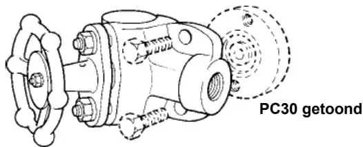
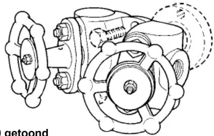
- Safety information
- Description
- Installation
- Welding the pipe connector
- Maintenance
- Depressurizing the pipework
- Available spares
1. Safety information
Safe operation of this product can only be guaranteed if it is properly installed, commissioned and maintained by qualified personnel (see the “Safety instructions” at the end of this document). The general good practices for pipe installation must also be complied with, and suitable tools and safety equipment must be used correctly.
2. Description
2.1 Overview
The PC3* and PC4* series are pipe connectors with an integrated piston-type stop valve (for further details, see technical information TI-P128-03 and TI-P128-02). The piston-type stop valve is sealed by a piston driven by a handwheel and threaded stem. The piston moves between two sealing rings separated by a guide sleeve. The stop valve is open when the piston is fully retracted and retained only by the upper sealing ring, ensuring that there is no leakage to the surrounding environment. The stop valve is closed when the piston is fully screwed in and retained by the lower sealing ring, preventing a leakage path between the inlet and outlet. The guide sleeve allows fluid to pass through the stop valve while keeping the upper and lower sealing rings separated. The stop valve therefore uses soft sealing: the piston contacts the sealing rings, which are held in place by bolts and a special patented sealing-ring material composition (laminated graphite/stainless steel), compensating for changes in pressure and temperature.
Other features of the piston-type stop valve are as follows:
The two cylindrical sealing surfaces, the lower sealing ring and the piston, come into contact only when the fluid has been shut off.
The piston is always restrained by at least one sealing ring, so no vibration is generated when the stop valve is opened or closed.
When the stop valve is fully open, the piston is fully retracted into the upper sealing ring and is protected from erosion, corrosion and the deposition of foreign matter.
2.2 Operation
The integrated piston-type stop valves should be fully open or fully closed. They are not suitable for regulating or throttling service. The stem of the piston-type stop valve moves up and down with the piston and indicates the opening position of the stop valve.
When closing the stop valve, the piston is kept continuously sealed by the handwheel. Therefore, never remove the handwheel from the stem during maintenance. Due to the large sealing area of the piston-type stop valve, a leak-tight seal can be achieved without using a valve wrench.
When opening the stop valve, the piston stops when the valve is fully open because its top contacts the inside of the body.
The handwheel must always be operated gently.
3. Installation
Note: Read the safety information at the end of this manual before starting installation.
3.1 Overview
Two conditions must be met to ensure that the swivel connector steam trap operates correctly and discharges condensate efficiently:
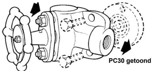
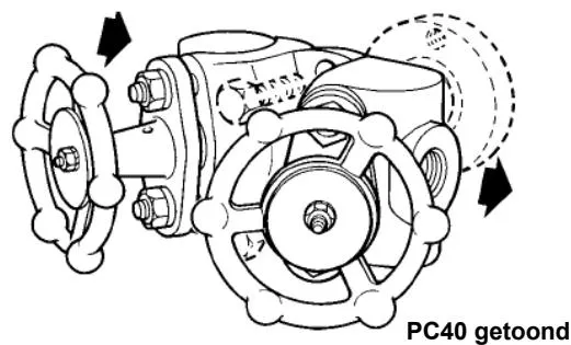
When installing PC3* and PC4*, the flow must follow the direction of the arrow on the body. The flow direction may be horizontal in either direction, vertical or inclined.
The connection face of the swivel connector steam trap must always be in a vertical plane.
Ensure that the handwheel is accessible for maintenance. After installation, insulating the pipe connector is recommended to minimize radiant heat loss and protect personnel from the risk of burns.
Note: Some types of steam trap must not be insulated.
The PC and steam trap are assembled with a spiral-wound gasket. It is important not to damage the sealing faces of the steam trap through welding, weld spatter, impact or other causes. Take particular care when installing the PC in the pipe network. It is recommended that the steam trap be installed as soon as the PC has been installed in the pipe network. Alternatively, the steam trap may be installed on the PC before the PC is installed in the pipe network.
3.2 Welding pipework for socket-weld versions (see Section 4)
It is difficult to specify a general welding procedure that meets the requirements of all national and international standards and codes, particularly with regard to the welding process, welding conditions (number of passes, filler-material dimensions, current, voltage and polarity), filler-material storage, and filler-material manufacturer/model, because many suitable welding-material suppliers are available. The following information is therefore provided only as guidance based on British Standards and as a basic requirement guide for welding socket-weld pipe connectors into pipework. The PC3* connector is designed for applications where the steam trap discharges directly to atmosphere only. If any backpressure exists, a separate stop valve and blowdown valve must be installed downstream. The PC4* connector is recommended for all applications in closed systems.
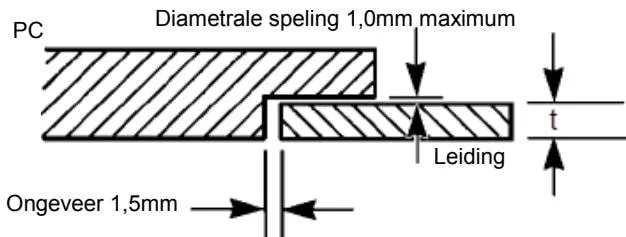
Reference: BS 2633: 1987: Section 3.1 and Figure 9
4. Welding the pipe connector
Note: The following information is provided only as guidance based on British Standards.
Weld DN15 and DN20 socket-weld pipe connectors to DN15 and DN20 Schedule 80 pipe.
Parent material
Description
PC3*, PC4* - Austenitic stainless steel, minimum tensile strength 485 N/mm²
Pipe - Carbon steel, minimum tensile strength 430 N/mm²
Specification
ASTM A182 F304L - PC3*, PC4*
ASTM A106 Gr B - Pipe
Material Group R - PC3*, PC4*, A1 - Pipe
Parent material dimensions
| DN15 | DN20 | |||
| PC | Pipe | PC | Pipe | |
| Thickness (mm) | 8.85 | 3.73 | 5.50 | 3.91 |
| Outside diameter (mm) | 39.00 | 21.30 | 39.00 | 26.70 |
Welding type
Socket-weld to BS 3799 Class 3000 lb
Welding process
Welding process: Manual metal arc welding (MMA)
Welding position: All positions, site welding
Welding preparation: As shown in the diagram
Filler material
Filler material:
Composition - Low carbon: 23% Cr: 12% Ni
Specification - BS 2926: 1984: 23-12 L BR
Shielding gas/flux: Not applicable
Preparation and cleaning
Socket: As supplied and cleaned with a wire brush
Pipe: Mechanically cut and cleaned with a wire brush
Additional information
The PC does not need to be dismantled before welding.
Use tack welding for assembly.
Parent material temperature
Preheat temperature
Preheating is required only when the ambient temperature is below 5 °C, followed by gentle heating.
Interpass temperature
Not applicable
Post-weld heat treatment
Not required
Welding sequence and completed weld dimensions
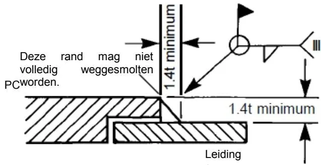
Reference: BS 806: 1990: Section 4: Clause 4.7.3
5. Maintenance
Note: Read the safety information at the end of this manual before starting any maintenance.
5.1 Introduction
All work must be carried out by suitably qualified and competent personnel. Before starting work, ensure that suitable tools are available. Use only Spirax Sarco spare parts.
5.2 Maintenance
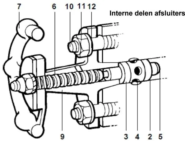
After the pipe connector is first put into service, or after replacing the sealing rings, gently tighten the valve cover nut (11) with the stop valve in the closed position. During tightening, ensure that the valve cover (9) remains straight and vertical, and operate the handwheel carefully. If there are signs of leakage, this procedure may be repeated. If a perfect seal cannot be achieved in this way, replace the stop valve seals according to the procedure below. The small-diameter hole in the valve cover initially prevents pressure from building up inside the valve cover. It also helps detect leakage from the upper sealing ring and is used to lubricate the stem (6) when the stop valve is closed.
5.3 Preparation for dismantling the stop valve
If maintenance is carried out while the pipe network is still at a high temperature, wear suitable protective clothing. If insulation is installed, remove it carefully. The steam trap does not need to be removed before dismantling the stop valve.
5.4 Dismantling the stop valve
Use the handwheel (7) to fully open the stop valve.
Remove the valve cover nut (11) and washer (12) from the bolts (10).
Carefully turn the handwheel in the closing direction so that the valve cover (9) rises.
Turn the valve cover (9) so that the flange bolt holes no longer align with the bolts (10).
Turn the handwheel in the opening direction to disengage the piston (5) from the sealing rings (2 and 3), and remove the piston/valve-cover assembly from the body (1).
The piston (5) is secured to the stem (6) by a ball or socket weld and must not be separated from it.
Check the piston (5) for scratches, corrosion or other signs that could prevent the stop valve from sealing perfectly.
Check the other components for wear or damage and replace them if necessary.
5.5 Resealing the stop valve
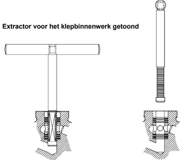
After dismantling the stop valve, pass the valve-internals extraction tool through the sealing rings (2 and 3) and guide sleeve (4).
Strike the tool firmly to ensure that it reaches the bottom, then turn the handle through one quarter turn and carefully remove the two sealing rings (2 and 3) and guide sleeve (4).
Thoroughly clean the sealing-ring housing and all internal components.
Install the new lower sealing ring (2), guide sleeve (4) and upper sealing ring (3), ensuring that they are fully seated. (Note: The lower and upper sealing rings are identical.)
Apply a thin film of graphite-based lubricant to the threads. Do not apply it to the internal components or piston.
5.6 Reassembling the stop valve
Take the piston/valve-cover assembly and turn the handwheel (7) in the opening direction until it reaches the stop.
Return the piston (5) into the upper sealing ring and press it down until the washer (12) can be installed. Screw the valve cover nut (11) onto the bolt (10) and tighten it by hand.
Fully close the stop valve, ensure that the valve cover (9) is straight and vertical, and gradually tighten the valve cover nut (11) to the recommended tightening torque of 10 Nm.
5.7 Replacing the steam trap and depressurizing the pipework
See Section 6
6. Depressurising the system
6.1 Operation of DV1 and DV2 fitted to PC33, PC34, PC35, PC43, PC44, PC46 and PC47 pipe connectors
| DV1 and DV2 depressurising valves are fitted to PC3_ or PC4_ series pipe connectors to provide safe and reliable depressurising/bypass of the steam trap. | |
| DV1 | Normally fitted to the upstream drain line and/or downstream test connection. (DV2 can be supplied where line drainage is required.) |
| DV2 | Always fitted to the upstream steam trap depressurising connection to ensure safe downward discharge. |
| For further details on operating the DV valves, see TI-P600-01 and IM-P600-02. Note: Always ensure that the discharge outlets of the DV1 and DV2 valves are piped to a safe location and that the correct safety precautions are taken when operating the valves. (See the "Safety information" section.) | |
Depressurising valves
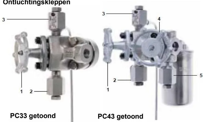
Upstream isolation valve
Upstream line drain valve (if fitted) - DV1 or DV2
Steam trap depressurising valve (if fitted) - DV1 or DV2
Downstream isolation valve
Downstream steam trap test valve - DV1 or DV2
6.2 Removing/replacing a steam trap fitted to PC30, PC33, PC34 or PC35 pipe connectors
Close the upstream isolation valve (1).
If fitted, open the line drain valve DV (2) and keep the steam line drained.
If installed in a system where direct discharge to atmosphere is not possible, ensure that all downstream pressure has been isolated and released before proceeding. Consider using a PC4_ connector.
If fitted, open the steam trap depressurising valve DV (3) to release the pressure. (Note: Under no circumstances should the adjusting screw be removed, as it prevents pressure release at the valve stem.)
If no DV valve is fitted, carefully remove the two steam trap bolts, ensuring that any residual steam/condensate can be safely released.
After removing the plastic protective sleeve from the new steam trap, replace the steam trap and tighten the bolts to the recommended torque.
Close DV valves (2) and (3), then slowly open the isolation valve (1) and check for leaks.
If no leakage is detected, fully open the isolation valve (1).
6.3 Removing/replacing a steam trap fitted to PC40, PC43, PC44, PC45, PC46 or PC47 pipe connectors
- Close the upstream and downstream isolation valves (1) and (4).
If fitted, open the line drain valve DV (2) and keep the upstream line drained.
If fitted, open the steam trap depressurising valve DV (3) and the steam trap test valve DV (5) to release the pressure. (Note: Under no circumstances should the adjusting screw be removed, as it prevents pressure release at the valve stem.)
If no DV valve is fitted, carefully remove the two steam trap bolts, ensuring that any residual steam/condensate can be safely released.
After removing the plastic protective sleeve from the new steam trap, replace the steam trap and tighten the bolts to the recommended torque.
Close DV valves (3) and (5), and close the line drain valve DV (2).
Fully open the isolation valve (4), then slowly open the isolation valve (1) and check for leaks.
If no leakage is detected, fully open the isolation valve (1).
6.4 Testing the steam trap
DV valve (5) (PC4_ series only) can be used to test the steam trap. Open the valve stem screw and observe the valve discharge to ensure that the steam trap is operating correctly. (Note: Under no circumstances should the adjusting screw be removed, as it prevents pressure release at the valve stem.) After observation is complete, close the screw and tighten it to the recommended torque.
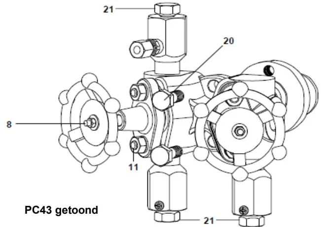
6.5 Recommended tightening torques
| Part | or mm | Nm | ||
| 11 | 14 UNC | 5/16" x 18 | 10 - 11 | |
| 8 | 10 | M6 | 0.1 | |
| 20 | 9/16" | 30 - 35 | ||
| 21 | 19 | 40 - 45 |
7. Available spare parts
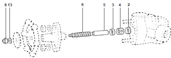
Available spare parts are shown in solid lines. Parts shown in broken lines are not available as spare parts. An extraction tool is provided to remove the seal rings for ease of replacement.
Available spare parts
| Seal ring set | 2, 3 | |
| Isolation valve internals, comprising: | Seal ring set | 2, 3 |
| Guide bush | 4 | |
| Plunger with spindle | 5, 6 | |
| Handwheel nut | 8 | |
| Washer | 13 | |
| Extraction tool | Not shown, see page 3 | |
How to order spare parts
Always order spare parts using the description in the “Available spare parts” table, stating the type and size of the material.
Example: 1 set of seal rings for a PC3_ pipe connector (DN15 socket weld connection) incorporating a plunger-type isolation valve.
Safety information
Avoiding risks when installing, using and maintaining Spirax Sarco products
Safe operation of these products can only be guaranteed when they are properly installed, commissioned and maintained by qualified personnel (see the “Permits to work” section below), in accordance with the installation and maintenance instructions. The general installation and safety instructions for pipeline and plant construction must also be complied with, and personnel must be fully familiar with the correct use of tools and safety equipment.
Intended use
Ensure that the product is suitable for its intended use by referring to the name-plate and technical information.
The products listed in the table below comply with the requirements of the European PED Directive 97/23/EC and carry the relevant marking, unless they fall within Article 3.3 of the Directive:
| Product | DN | Category | ||||
| Minimum | Maximum | Gases | Liquids | |||
| G1 | G2 | G1 | G2 | |||
| PC3_/PC4_ | 1/2" | 3/4" | - | Art.3.3 | - | Art.3.3 |
i) This product has been specifically designed for use with:
Steam
Water
Compressed air
Use with other fluids is possible, but must be agreed in advance with Spirax Sarco.
ii) Verify the suitability of the materials and the compatibility of the maximum and minimum allowable operating pressures and temperatures. If the maximum operating limits of the product are lower than those of the system in which it is installed, or if product failure could result in dangerous overpressure or overtemperature, the system must be fitted with suitable overpressure and/or overtemperature protection devices.
iii) Follow the installation instructions strictly, particularly with regard to installation and fluid direction and flow.
iv) Spirax Sarco products are not designed to withstand external loads that may be induced by the system in which they are installed. The installer must assess these external loads and take all necessary precautions to minimise them.
v) Remove all connection-end protective covers before installation.
Accessibility
Before installing the product in a pipeline system and/or working on an installed product, ensure safe accessibility and, where necessary, provide a suitable protected working platform.
Lighting
Ensure that adequate lighting is provided so that all details of the product and its surroundings can be clearly observed.
Hazardous gases and/or liquids in the pipeline
Check what substances are present or have previously been present in the pipeline. If the fluid could cause fire, explosion or a health hazard, take appropriate precautions.
Hazardous environments around the product
Check and assess the risks of explosion, the availability of sufficient breathing air (for example, in tanks and pits), the possible presence of toxic gases, extremely high ambient temperatures, hot surfaces (for example, resulting from welding), excessive noise and moving machinery.
The system
Check and assess the effect of installing the product on the complete system. Ensure that any operation on the product (for example, operating handwheels and/or handles, thermal insulation and electrical isolation) will not place any part of the system or any person at risk.
Exercise extra care when temporarily disabling alarm systems or shutting down exhaust and/or ventilation systems. Open and close isolation valves gradually to prevent system shock.
Pressure systems
Ensure that system pressure is completely released and that there is a sufficiently sized vent. Where possible, double-isolate the pressure-containing parts of the system. Lock isolation valves in the closed position and/or attach clear warning labels. Do not rely on pressure gauge readings indicating the absence of pressure.
Temperature
Allow sufficient time for the product to cool after isolation to avoid burns. Wear protective clothing and safety glasses.
Tools and spare parts
Before starting work, ensure that the required tools and spare parts are available. Use only genuine Spirax Sarco spare parts. Never reuse used seals.
Protective clothing
Check and assess whether protective clothing is required to protect against hazards such as chemicals, extremely high and/or low temperatures, radiation, noise, falling objects, and eye or facial injury.
Permits to work
All work must be carried out and/or supervised by suitably competent personnel. Installation and operating personnel should be trained in the correct use of the product in accordance with the installation and maintenance instructions. Where required, a permit to work must be applied for and issued. Permit-to-work procedures must be strictly followed. Where a permit to work is not required, it is recommended that a responsible person familiar with the installation be appointed and, where necessary, assisted by a safety officer. Warning notices should also be posted where necessary.
Handling
Manual handling of large and/or heavy products may cause injury. Lifting, pushing, pulling, carrying and/or supporting loads by bodily force is strenuous and may cause back injury. Assess the risk of injury by considering the nature of the work, the personnel, the load size and the working environment. Use a suitable method of handling for all these conditions.
Residual hazards
The surface of the product may remain hot for a considerable time after the product has been taken out of service. If these products are used at their maximum operating temperature, the surface temperature may reach 400 °C.
Please note that some products do not completely drain when they are dismantled, and hot liquid may remain inside (see the installation and maintenance instructions).
Risk of freezing
Provision must be made to protect products that are not completely drained against freezing during shutdown or periods of low load.
Disposal
Unless otherwise stated in the installation and maintenance instructions, these products are fully recyclable and can be safely disposed of through the recycling process without environmental contamination.
Returning products
Customers and distributors are reminded that, under environmental regulations, returned products must be accompanied by information concerning any hazardous residues that may be present in the products and the precautions to be taken. This information must be supplied in writing with the product and must include all necessary health and safety data for any hazardous or potentially hazardous substances.