
Contents
- Safety Information
- Product Overview
- Installation
- Commissioning
- Operation
- Maintenance
- Spare Parts
1. Safety Information
Safe operation of this product can only be guaranteed if it is properly installed, commissioned, operated and maintained by qualified personnel (see Section 1.11) in accordance with these Installation and Maintenance Instructions. General installation and safety requirements for pipeline and plant construction, as well as the correct use of tools and safety equipment, must also be observed.
1.1 Intended Use
Refer to these Installation and Maintenance Instructions, the product nameplate and the Technical Information Sheet to confirm that the product is suitable for the intended use or application.
The products listed in the table below comply with the requirements of the European Pressure Equipment Directive 2014/68/EU and are marked accordingly where required.
The Pressure Equipment Directive categories for these products are as follows:
| Product | Group 2 Gases | Group 2 Liquids |
| SCA Series | SEP | SEP |
i) This product has been specifically designed for use with steam, air or water/condensate, which are included in Group 2 of the above Pressure Equipment Directive. The product may be suitable for use with other fluids, but where this is considered, Spirax Sarco should be contacted to confirm the suitability of the product for the proposed application.
ii) Check material suitability and pressure and temperature limits, including maximum and minimum values. If the maximum operating limits of the product are lower than those of the system in which it is installed, or if product failure could result in dangerous overpressure or overtemperature, ensure that a safety device is installed in the system to prevent these limits from being exceeded.
iii) Determine the correct installation position and fluid flow direction.
iv) Spirax Sarco products are not designed to withstand external stresses imposed by the system to which they are connected. It is the installer’s responsibility to consider these stresses and take adequate precautions to minimise them.
v) Remove all protective covers from connection ports before installation.
1.2 Access
Before working on the product, ensure safe access is available. Where necessary, provide a safe working platform with suitable guarding. If lifting is required, suitable lifting equipment must be provided.
1.3 Lighting
Ensure adequate lighting, particularly where detailed or precise work is required.
1.4 Hazardous Liquids or Gases in the Pipeline
Consider what media may be or may have been present in the pipeline, for example: flammable materials, substances hazardous to health and extreme temperatures.
1.5 Hazardous Environment Around the Product
Consider: explosive atmospheres, oxygen-deficient environments such as tanks and pits, hazardous gases, extreme temperatures, hot surfaces, fire hazards such as during welding, excessive noise and moving machinery.
1.6 The System
Consider the effect of the proposed work on the complete system. Could any intended action, such as closing isolation valves or electrical isolation, put another part of the system or personnel at risk?
Hazards may include isolating vents or protective devices, or rendering controls or alarms ineffective. Isolation valves should be opened and closed gradually to avoid system shock.
1.7 Pressure Systems
Ensure that all pressure is isolated and safely vented to atmospheric pressure.
Consider double isolation, double block and bleed, and locking or tagging closed valves. Do not assume that a system has been depressurised even when the pressure gauge indicates zero.
1.8 Temperature
After isolation, allow sufficient time for the temperature to return to normal to avoid the risk of burns.
1.9 Tools and Consumables
Before starting work, ensure that suitable tools and/or consumables are available. Use only genuine Spirax Sarco spare parts.
1.10 Protective Clothing
Consider whether you and/or others in the vicinity require protective clothing to protect against hazards such as chemicals, high or low temperatures, radiation, noise, falling objects, and eye or face injuries.
1.11 Permit to Work
All work must be carried out by suitably competent persons or under their supervision.
Installation and operating personnel must be trained in the correct use of the product in accordance with these Installation and Maintenance Instructions.
Where a formal permit-to-work system is in force, it must be complied with. Where no such system exists, it is recommended that a responsible person is aware of the work being carried out and, where necessary, arranges for an assistant whose primary duty is safety supervision.
Post warning notices where necessary.
1.12 Handling
Manual handling of large and/or heavy products may result in injury. Lifting, pushing, pulling, carrying or supporting a load by physical effort can cause injury, particularly to the back. It is recommended that the risks associated with the task, personnel, load and working environment are assessed and that an appropriate handling method is used according to the circumstances of the work.
1.13 Residual Hazards
Under normal operating conditions, the external surface of the product may become very hot. When operated at the maximum permitted operating conditions, surface temperatures of some products may exceed 425 °C (797 °F).
Many products are not self-draining. Take care when dismantling or removing the product from an installation. Refer to the Maintenance Instructions.
1.14 Freezing
For products that are not self-draining, precautions must be taken to prevent freeze damage in environments where temperatures may fall below freezing point.
1.15 Disposal
Unless otherwise stated in these Installation and Maintenance Instructions, this product is recyclable and is not expected to present an ecological hazard when disposed of properly.
Visit the Spirax Sarco product compliance webpage https://www.spiraxsarco.com/productcompliance for the latest information on relevant substances that may be contained in this product. If no additional information is provided on that webpage, this product can be safely recycled and/or disposed of, provided it is handled correctly. Always check local recycling and disposal regulations.
1.16 Returning Products
Customers and distributors are reminded that, under EC Health, Safety and Environmental Law, when returning products to Spirax Sarco, they must provide hazard information and any precautions to be taken where residual contamination or mechanical damage could present a health, safety or environmental risk. This information must be provided in writing and include Health and Safety Data Sheets for any substances identified as hazardous or potentially hazardous.
1.17 Safe Use of Cast Iron Products in Steam and Condensate Systems
When installed correctly in accordance with good steam engineering practice, these products are safe to use.
However, due to their mechanical properties, they are more brittle than materials such as ductile iron or carbon steel. To prevent water hammer and ensure safe operating conditions in steam systems, the following good engineering practices should be observed.
Safe Handling
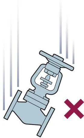
Cast iron is a brittle material. If the product is dropped during installation and there is a risk of damage, it must not be used unless it has been fully inspected and pressure tested by the manufacturer.
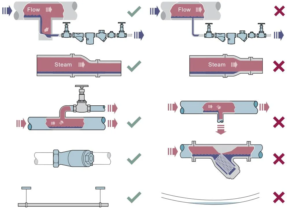
Prevention of Water Hammer
Steam main drainage:
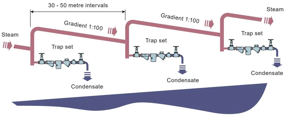
Steam main considerations:
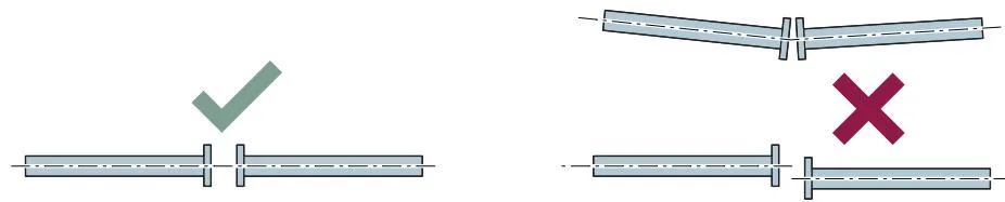
Prevention of Tensile Stress
Pipe misalignment:
Product installation or reassembly after maintenance:


Do not overtighten. Use the correct torque values.
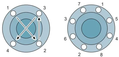
Flange bolts should be tightened progressively in a diametrically opposed sequence to ensure even loading and correct alignment.
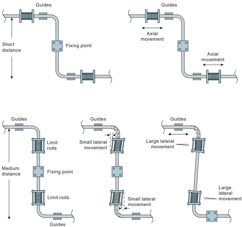
Thermal expansion:
2. Product overview
2.1 Product description
The Spirax Sarco SCA range comprises maintainable carbon steel inverted bucket steam traps with straight-through connections, suitable for a wide pressure range, and an integral strainer.
Note: For more information, see the Technical Data Sheet TI-P077-05.
2.2 Sizes and pipe connections
½”, ¾” and 1” threaded connections BSP T Rp (ISO 7-1) or NPT, and socket-weld ends to ANSI B16.11 Class 3000. DN15, DN20 and DN25 flanged connections to PN40, ANSI 150 and ANSI 300.
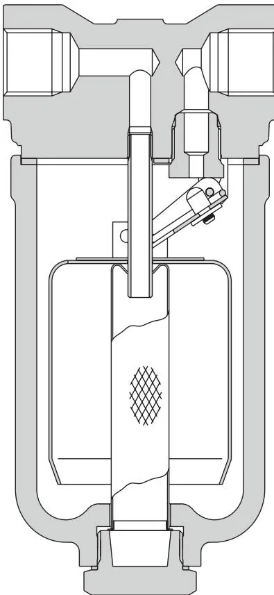
Figure 1: SCA range inverted bucket steam trap
2.3 Pressure/temperature limits (ISO 6552)
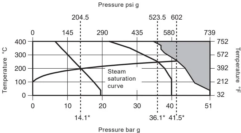
The product must not be used in this area.
*PMO is the recommended maximum operating pressure for saturated steam.
- A - B: Flanged ANSI 300, threaded and socket-weld
- A - C: Flanged BS 4504 PN40 (ISO 7005.1)
- A - D: Flanged ANSI 150
Maximum operating conditions depend on the orifice size.
| Body design conditions | ANSI/ASME 300 (PN50) | ||
| PMA | Maximum allowable pressure | 51 bar g | (739 psi g) |
| TMA | Maximum allowable temperature | 400 °C | (752 °F) |
| Maximum design cold water hydraulic test pressure | 78 bar g | (1 131 psi g) | |
The SCA30 has been verified as safe for use under full vacuum conditions.
DPMX - Maximum differential pressure
DPMX - Maximum differential pressure bar
| Size | 3 | 5 | 11 | 15 | 30 | 40 |
| DN15 1/2" | SCA3 | SCA5 | SCA11 | SCA15 | SCA30 | SCA40 |
| DN20 3/4" | ||||||
| DN25 1" |
SCA15, SCA30 and SCA40 are standard supply models; SCA3, SCA5 and SCA11 can be ordered on special request.
Note: The pressure limits of the specified flange must be higher than the pressure limits of the internal mechanism. The table below is for reference.
| Flange | Pressure (saturated) | Available mechanism |
| ANSI 150 | 14.1 bar g | SCA3, 5, 11 (SCA15 limited to 14.1 bar g) |
| ANSI 300 | 41.6 bar g | All models |
| PN40 | 36.1 bar g | SCA3, 5, 11, 15, 30 (SCA40 limited to 36.1 bar g) |
3. Installation
Note: Before carrying out any installation work, read Section 1, ‘Safety information’.
Refer to these installation and maintenance instructions, the product nameplate and the technical data sheet to confirm that the product is suitable for the proposed installation:
3.1 Check the materials, pressure and temperature and their maximum values. If the maximum operating limits of the product are lower than those of the system in which it is installed, ensure that safety devices are fitted in the system to prevent overpressure.
Determine the correct installation position and fluid flow direction.
Remove all protective caps from the connections.
3.4 The steam trap must be installed with the body vertical so that the bucket moves vertically. The inlet and outlet connections should be on the same horizontal plane, and the steam trap should be installed below the drainage point so that a water seal is maintained around the open end of the bucket. Inverted bucket steam traps cannot discharge air quickly. Particularly in process applications, this may result in slow warm-up and waterlogging of the steam space. A separate external air vent valve is therefore required in parallel to vent air efficiently. Any bypass should be installed above the steam trap. If the bypass is below and leaks or remains open, the water seal may be blown away, causing steam loss.
3.5 If the steam trap is installed in a superheated steam system, a check valve should be installed on the inlet side of the steam trap to prevent loss of the water seal. It may be necessary to prime the steam trap with water before commissioning.
3.6 When inverted bucket steam traps are installed in exposed locations, insulation can reduce the risk of freezing damage. Confirm that the required tools are available before starting installation.
3.7 Slowly open the isolation valve until normal operating conditions are reached.
3.8 Check for leaks and confirm correct operation.
Note: If the steam trap discharges to atmosphere, ensure that it discharges to a safe location; the temperature of the discharged fluid may reach 100 °C (212 °F).
4. Commissioning
After installation or maintenance, confirm that the system is functioning correctly. Test any alarms or protective devices.
5. Operation
Under most operating conditions, the steam trap discharges condensate in ‘intermittent bursts’. In low-load and/or low-pressure applications, discharge may tend to be a continuous dribble.
Condensate is discharged at steam temperature, so care must be taken to ensure the discharge location is safe.
6. Maintenance
Note: Before carrying out any maintenance procedure, read Section 1, ‘Safety information’.
Warning
The cover gasket contains a thin stainless steel support ring, which may cause personal injury if handled or disposed of incorrectly.
6.1 General information
Before carrying out any maintenance on the steam trap, it must be isolated from the steam supply and condensate return lines, the pressure safely vented to atmosphere, and the steam trap allowed to cool. When reassembling, ensure that all joint faces are clean.
6.2 How to install the valve and seat assembly
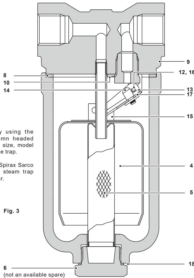
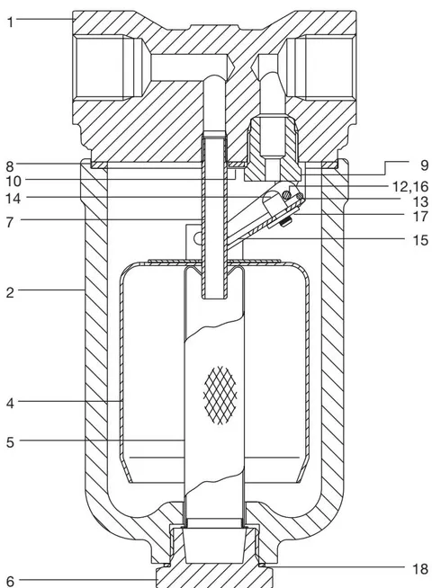
- Isolate the inverted bucket steam trap, loosen the cover bolts (3) and remove the cover.
- Loosen the two screws (11) and remove the complete bucket assembly.
- Remove the seat (9).
- Apply a small amount of sealant to the threads, confirm the joint faces are clean, then screw in the new seat to the recommended torque (see Table 1).
- Secure the new bucket assembly using the new screws (11) supplied in the spare parts kit, align the valve head with the orifice, and tighten the screws to the recommended torque (see Table 1).
- Using new gaskets, reassemble the body to the recommended torque (see Table 1) and reconnect the outlet line.
- Slowly open the isolation valve to allow pressure and temperature to increase in a controlled manner.
- Check for leaks.
Table 1 Recommended tightening torques
| Item | Part | Spanner A/F | Thread | N·m | (lbf·ft) |
| 3 * | Cover bolts | 14 A/F | M10 | 40 - 45 | 30 - 33 |
| 6 | Strainer cap | 32 A/F | M28 | 170 - 190 | 125 - 140 |
| 9 | Seat | 17 A/F | M16 | 35 - 40 | 26 - 30 |
| 11 * | Valve head guide plate screws | Posidrive | M4 x 6 | 2.5 - 3.0 | 2.0 - 2.5 |
6.3 How to clean/replace the strainer screen
- Unscrew the strainer cap (6).
- Remove the strainer screen (5).
- Clean or replace the strainer screen and reassemble using a new strainer cap gasket (18).
- Tighten the strainer cap (6) to the recommended torque (see Table 1).
- Slowly open the isolation valve to allow pressure and temperature to increase in a controlled manner.
- Check for leaks.
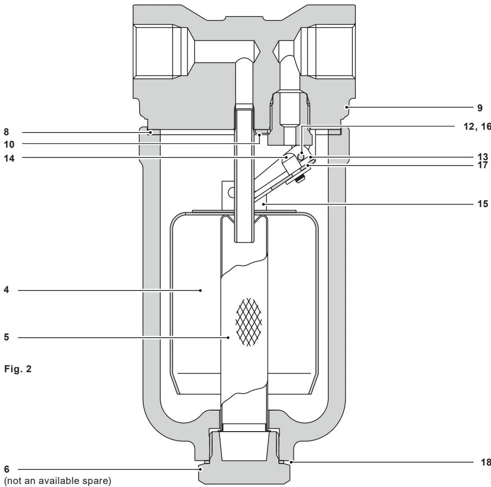
7. Spare parts
Spare parts are supplied as shown. Other parts are not available as spare parts.
Available spares
| Internal components (state pressure range) | 4, 8, 9, 10, 11 (2 pieces)*, 12, 13, 14, 15, 16 (2 pieces), 17 |
| Strainer assembly | 5, 18 |
| Cover and strainer gaskets (set of 3) | 8, 18 |
*Part 11 (valve head guide plate screws) is not shown.
Ordering spare parts
Always order spare parts as described in the ‘Available spares’ column and state the steam trap size, model and pressure rating.
Example: 1 - Internal components, for a Spirax Sarco DN20, SCA15 inverted bucket steam trap, pressure rating 15 bar.