
1. Safety Information
Compliance with the operating instructions, together with correct installation, commissioning and maintenance by qualified personnel, is the only guarantee of safe operation of this product (see Section 1.11). After installation, the installation and safety guidelines for the pipework and plant construction must be followed, and personnel must understand the correct use of tools and be equipped with the necessary safety equipment.
1.1 Intended Use
Refer to the Installation and Maintenance Instructions, name-plate and technical documentation to ensure that the product is suitable for the intended use. The products listed in the table below fully comply with the European Pressure Equipment Directive 97/23/EC and ATEX Directive 94/9/EC, and CE and ® markings can be supplied where required. The Pressure Equipment Directive classifications are as follows:
| Product | Specification | Group 1 gases | Group 2 gases | Group 1 liquids | Group 2 liquids |
|---|---|---|---|---|---|
| APT14 | - | 1 | - | SEP | |
| APT14HC | - | 2 | - | SEP | |
| APT14SHC | - | 2 | - | SEP | |
| DCV10 | DN40 PN25 | - | SEP | - | SEP |
| DCV10 | DN50 Class 300 | - | 1 | - | SEP |
| Motive steam strainer | DN15 | SEP | SEP | SEP | SEP |
The product label complies with ATEX Directive 94/9/EC x II 2G CT3.
I) The product is designed for Group 2 fluids under the Pressure Equipment Directive, including steam, air and water/condensate. For use with other fluids, consult Spirax Sarco. II) Ensure that the materials are suitable for the operating conditions and that the maximum and minimum system pressures and temperatures are within the product’s design range. If the product’s maximum operating range is lower than the system operating conditions, or if product failure could result in overpressure or overtemperature, install safety devices to address the hazard. III) Ensure that the product is installed correctly and that the inlet and outlet are not connected incorrectly. IV) Spirax Sarco products are not designed to withstand external stresses. The installer must prevent external forces in the system from acting on the product. V) Before installation, remove the protective covers from all product connections, including the cardboard flange covers.
1.2 Accessibility
After installation, ensure that there is sufficient access for operation. Where necessary, provide a safe working platform before operating the product. Lifting equipment should be provided where necessary.
1.3 Lighting
Ensure that adequate lighting is available, particularly when carrying out detailed or complex operations.
1.4 Hazardous Fluids or Gases in the Pipeline
Consider in advance what fluids are present, or may have been present, in the pipeline. Be aware of flammable substances, substances hazardous to health, and fluids at high or low temperatures.
1.5 Hazardous Working Environment
Hazards may include explosion risk, lack of oxygen, such as inside tanks or in low-lying areas, hazardous gases, high or low temperatures, hot surfaces, fire hazards, such as during welding, excessive noise and moving machinery.
1.6 The System
Understand the operation of the entire system. Before carrying out any operation, such as closing an isolation valve or operating an electrical switch, consider whether it could place other parts of the system or other personnel at risk.
Hazards include isolating ventilation ducts or protective devices and disabling control or alarm devices. Open and close isolation valves slowly to prevent system shock.
1.7 Pressure Systems
Ensure that system pressure is isolated or fully vented. Consider isolating the system with double isolation valves and locking or tagging closed valves. Do not assume that a pressure gauge reading of zero means that the system has been completely depressurized.
1.8 Temperature
After isolating the product, allow it to cool to room temperature to avoid burns.
1.9 Tools and Spare Parts
Before operation, ensure that suitable tools and spare parts are available. Use genuine Spirax Sarco spare parts only.
1.10 Protective Clothing
Consider whether operators or nearby personnel should wear protective clothing to prevent hazards caused by chemicals, high or low temperatures, radiation, noise, falling objects, or injury to the eyes and face.
1.11 Permits to Work
All work must be carried out by competent personnel or under their supervision. Installation and operating personnel must be trained in accordance with the product’s Installation and Maintenance Instructions so that they can use the product correctly.
Where a permit-to-work system is in operation, personnel must comply with it. Where such a system is not in operation, the person responsible must understand the nature of the work and, where necessary, assign a safety supervisor.
Where necessary, warning notices should be displayed.
1.12 Handling
Manual handling of large or heavy products may cause injury. Lifting, pushing, pulling, carrying or supporting heavy loads with the body can cause injury, particularly back injuries. It is recommended that the workload, individual capability, load and working environment be assessed, and that appropriate handling methods be adopted according to site conditions.
Please Note
For the product weight and internal mechanism, refer to Section 2.
Product-Specific Safe Lifting Information
Please note that the body of the Spirax Sarco APT14 pump has tapped or plain holes. Whether these holes can be used for lifting purposes is entirely the purchaser’s responsibility to determine.
The purchaser is responsible for selecting the correct lifting eye bolts or U-hook assemblies and for the lifting operation and the competence of the personnel carrying it out. Spirax Sarco ensures that the flat surface at the opening of each tapped hole is larger than the shoulder of a standard lifting eye bolt, allowing the lifting eye bolt to be screwed down to the shoulder. However, the shoulder dimensions alone cannot determine whether the lifting eye bolt is capable of lifting the product.
Spirax Sarco accepts no responsibility for possible product damage resulting from incorrect or inappropriate lifting.
Spirax Sarco ensures that the dimensions and thread form of the tapped holes are identified. Spirax Sarco also works with third-party organizations, and one sample from each product is selected for the relevant testing. Test details and certificates can be provided where required.
In addition, Spirax Sarco is not obliged to machine tapped or plain holes in every product. A disclaimer will be attached to the product stating that, in accordance with LOLER regulations, the purchaser is responsible for the safe unloading and lifting of the product at the plant.
1.13 Residual Heat
During normal use, the external surfaces of the product may become very hot. If operated at the maximum permitted operating temperature, the product surface temperature may reach 200°C (392°F).
The product is not self-draining. Care must be taken when removing or moving the product from its installed position (refer to the Maintenance Instructions).
1.14 Freezing
For non-self-draining products used at ambient temperatures below freezing, protection against frost must be provided.
1.15 Disposal
Unless otherwise stated in the Installation and Maintenance Instructions, this product is recyclable and presents no ecological hazard when disposed of properly.
1.16 Returning Products
In accordance with EC health, safety and environmental regulations, when returning products, customers and resellers must provide hazard information and carefully handle any residual contamination or mechanical damage that may present a health, safety or environmental hazard. Hazard information must be provided in writing, including health and safety data sheets, stating any identified or potential hazards.
2. Product Information
2.1 Description
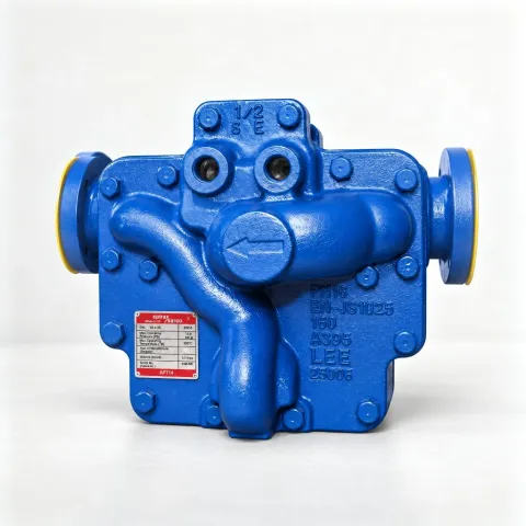
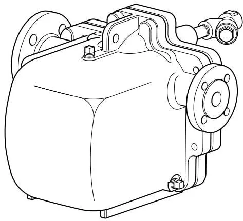
The Spirax Sarco automatic pump trap has a design pressure of PN16 and is available with threaded or flanged connections. The unit automatically drains or pumps condensate according to the operating conditions of the pipeline. Steam-driven, it removes condensate from equipment under all operating conditions, including vacuum.
The pump body is designed in accordance with AD-Merkblätter / ASME VIII standards.
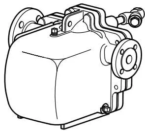
Figure 1 APT14
Options
The bodies and covers of the APT14 and APT14HC can be supplied with electroless nickel plating (ENP coating). For ENP coating, specify the product descriptions APT14 ENP and APT14HC ENP when ordering.
The bodies of the APT14, APT14HC and APT14SHC can be drilled and tapped for the installation of a sight glass.
Note: Specify the requirement for body drilling when ordering.
Sight glasses for the APT14, APT14HC and APT14SHC are supplied separately. For further details, contact Spirax Sarco.
Standards
The equipment complies with the European Pressure Equipment Directive 97/23/EC and the ATEX Directive 94/9/EC. CE and ® markings can be supplied where required.
Certificates
An EN 10204 3.1 certificate can be supplied for this product. Note: Specify the certificate requirement when ordering.
2.2 Sizes and Pipe Connections
| Model and pump body material | Inlet and outlet sizes and pipe connections | Motive steam inlet flange | Motive steam inlet thread | Motive steam/exhaust outlet |
|---|---|---|---|---|
| APT14 (ductile iron) | Flanged - DN40 inlet x DN25 outlet | EN 1092 PN16 | BSP or NPT | DN15 (1/2”) |
| APT14 (ductile iron) | Flanged - DN40 inlet x DN25 outlet | ANSI 150 B 16.5 | NPT | DN15 (1/2”) |
| APT14 (ductile iron) | Flanged - DN40 inlet x DN25 outlet | JIS 10 (JIS B 2210) | BSP | DN15 (1/2”) |
| APT14 (ductile iron) | Flanged - DN40 inlet x DN25 outlet | KS 10 (KS B 1511) | BSP | DN15 (1/2”) |
| APT14 (ductile iron) | Threaded - 1 1/2” inlet x 1” outlet | BSP (BS 21 parallel thread) | BSP | DN15 (1/2”) |
| APT14 (ductile iron) | Threaded - 1 1/2” inlet x 1” outlet | NPT | NPT | DN15 (1/2”) |
| APT14HC (ductile iron) | Flanged | EN 1092 PN16 | BSP | DN15 (1/2”) |
| APT14HC (ductile iron) | Flanged | ASME B 16.5 (ANSI) 150 | NPT | DN15 (1/2”) |
| APT14SHC (carbon steel) | Flanged - DN50 inlet x DN40 outlet | JIS 10 (JIS B 2210) | BSP | DN15 (1/2”) |
| APT14SHC (carbon steel) | Flanged - DN50 inlet x DN40 outlet | KS 10 (KS B 1511) | BSP | DN15 (1/2”) |
2.3 Pressure/Temperature Limits - APT14 and APT14HC (Ductile Iron)
See Section 2.4 for APT14SHC.
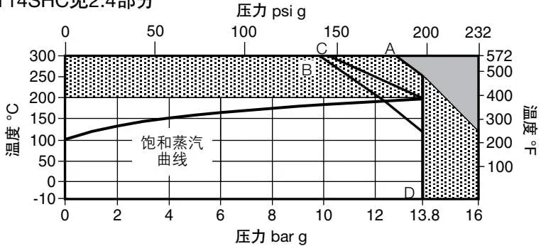

This product must not be used in this area.

This product must not be used in this area, otherwise damage to internal components may result.
A - D flanges PN16. B - D flanges JIS/KS 10. C - D flanges ANSI 150.
| Category | Parameter | Metric | Imperial |
|---|---|---|---|
| Pump body design conditions | PN16 | ||
| Maximum motive steam inlet pressure | 13.8 bar g | (200 psi g) | |
| PMA | Maximum allowable pressure | 16 bar g @ 120°C | (232 psi g @ 248°F) |
| TMA | Maximum allowable temperature | 300°C @ 12.8 bar g | (572°F @ 186 psi g) |
| Minimum allowable temperature | -10°C | (14°F) |
Note: Consult Spirax Sarco for lower operating temperatures.
| Parameter | Metric | Imperial |
|---|---|---|
| PMO maximum operating pressure for saturated steam | 13.8 bar g @ 198°C | (200 psi g @ 388°F) |
| Maximum backpressure - standard pump mode | 5 bar g | (72.5 psi g) |
| TMO maximum operating temperature for saturated steam | 198°C @ 13.8 bar g | (388°F @ 200 psi g) |
| Minimum operating temperature | -10°C | (14°F) |
Note: Consult Spirax Sarco for lower operating temperatures.
| Category | Parameter | Metric | Imperial |
|---|---|---|---|
| Temperature (ambient) | -10°C to 200°C | (14°F to 392°F) | |
| Design cold hydraulic test pressure | 24 bar g | (348 psi g) | |
| Recommended installation height (from pump base) | 0.3 m | (12”) | |
| Installation height | Recommended maximum installation height (from pump base); consult Spirax Sarco for greater installation heights | 1 m | (39”) |
| Minimum installation height (from pump base) | 0.2 m | (8”) |
2.4 Pressure/Temperature Limits
APT14SHC (Carbon Steel) - see Section 2.3 for APT14 and APT14HC.
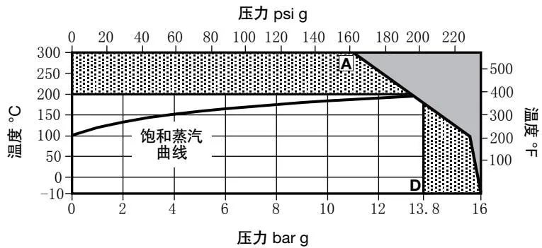
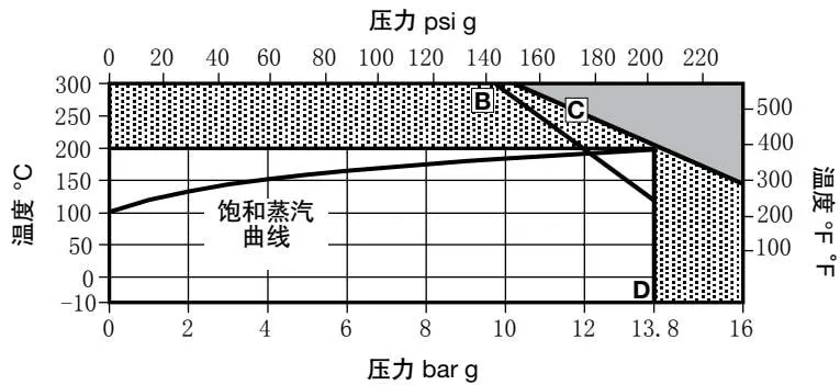

This product must not be used in this area.

This product must not be used in this area, otherwise damage to internal components may result.
A - D flanges PN16. B - D flanges JIS/KS 10. C - D flanges ANSI 150.
| Category | Parameter | Metric | Imperial |
|---|---|---|---|
| Pump body design conditions | PN16 | ||
| Maximum motive steam inlet pressure | 13.8 bar g | (200 psi g) | |
| PMA | Maximum allowable pressure | 16 bar g @ 120°C | (232 psi g @ 248°F) |
| TMA | Maximum allowable temperature | 300°C @ 12.8 bar g | (572°F @ 186 psi g) |
| Minimum allowable temperature | -10°C | (14°F) |
Note: Consult Spirax Sarco for lower operating temperatures.
| Parameter | Metric | Imperial |
|---|---|---|
| PMO maximum operating pressure for saturated steam | 13.8 bar g @ 198°C | (200 psi g @ 388°F) |
| Maximum backpressure - standard pump mode | 5 bar g | (72.5 psi g) |
| TMO maximum operating temperature for saturated steam | 198°C @ 13.8 bar g | (388°F @ 200 psi g) |
| Minimum operating temperature | -10°C | (14°F) |
Note: Consult Spirax Sarco for lower operating temperatures.
| Category | Parameter | Metric | Imperial |
|---|---|---|---|
| Temperature (ambient) | -10°C to 200°C | (14°F to 392°F) | |
| Design cold hydraulic test pressure | 24 bar g | (348 psi g) | |
| Recommended installation height (from pump base) | 0.3 m | (12”) | |
| Installation height | Recommended maximum installation height (from pump base); consult Spirax Sarco for greater installation heights | 1 m | (39”) |
| Minimum installation height (from pump base) | 0.2 m | (8”) |
2.5 Rated Capacity
Contact Spirax Sarco for the capacity required for a specific application. The following information is required for correct selection of the automatic pump-trap:
- Available installation height (m): the height from the base of the automatic pump-trap to the centre line of the condensate outlet from the heat exchanger or process equipment; if the outlet is vertically downward, this is the distance from the base of the pump-trap to the outlet face of the heat exchanger or process equipment.
- Available motive steam pressure (bar g).
- Total backpressure in the condensate return line (bar g), as detailed in the note below.
- Operating pressure of the heat exchanger at full load (bar g).
- Maximum steam load of the heat exchanger (kg/h).
- Minimum inlet temperature of the heated medium (°C).
- Maximum controlled temperature of the heated medium (°C).
| Item | APT14 | APT14HC |
|---|---|---|
| Pump capacity/cycle | 5 L (1.1 gallons) | 8 L (1.76 gallons) |
| Capacity in maximum condensate discharge mode at 1 m installation height, 5 bar g motive steam and 1 bar g backpressure | 4000 kg/h (8820 lb/h) | 9000 kg/h (19845 lb/h) |
| Capacity in maximum pumping mode at 1 m installation height, 5 bar g motive steam and 1 bar g backpressure | 1100 kg/h (2425 lb/h) | 2800 kg/h (6174 lb/h) |
Note
The table above shows the capacity achievable by the automatic pump-trap under the specified installation conditions. The specific installation conditions are given in the first column on the left.
The capacity of the automatic pump-trap will vary with different installation conditions and parameters. Consult Spirax Sarco for the capacity required for a specific application.
To achieve the rated capacity, the total lift or backpressure BP of the automatic pump-trap, comprising the static head and the pressure in the condensate pipe, must be lower than the motive steam pressure.
BP (backpressure) = (H × 0.0981) + (P) + (Pf)
That is: height (H) in m × 0.0981 + pressure in the condensate pipe (P) in bar g + flow friction resistance in the downstream pipe (Pf) in bar.
(The flow friction resistance Pf in the pipe may be ignored if the downstream pipe is less than 100 m long, the condensate pipe is not flooded, and the effect of flash steam at the maximum operating load of the heat exchanger has been considered when sizing the pipe.)
2.6 Dimensions/Weight
Metric (approx.) mm and kg
| Model | Connection | A | B | C | D | E | F | G | H | I | J | Weight |
|---|---|---|---|---|---|---|---|---|---|---|---|---|
| APT14 | Threaded | 350 | 198 | 246 | 385 | 304 | 258 | 57 | 250 | - | - | 198 |
| APT14 | Flanged | 389 | 198 | 246 | 385 | 304 | 258 | 57 | 250 | - | - | 198 |
| APT14HC | Flanged | 476 | 198 | 270 | 400 | 335 | 261 | 57 | 275 | 31.5 | 45 | 198 |
| APT14SHC | Flanged | 508 | 206 | 278 | 407 | 351 | 261 | 57 | 275 | 31.5 | 45 | 206 |
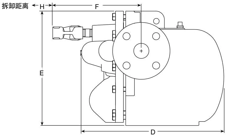
Note: A DCV10 check valve must be installed at the outlet of the APT14HC and APT14SHC.
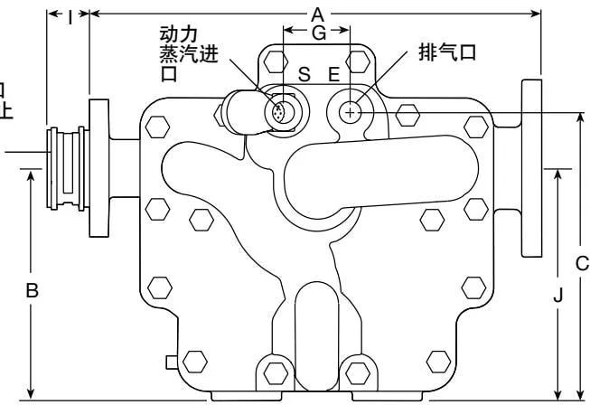
Figure 2 Imperial (approx.) inches and lbs
| Model | Connection | A | B | C | D | E | F | G | H | I | J | Weight |
|---|---|---|---|---|---|---|---|---|---|---|---|---|
| APT14 | Threaded | 13.78 | 7.8 | 9.69 | 15.16 | 11.97 | 10.16 | 2.24 | 9.84 | - | - | 7.80 / 99.26 |
| APT14 | Flanged | 15.31 | 7.8 | 9.69 | 15.16 | 11.97 | 10.16 | 2.24 | 9.84 | - | - | 7.80 / 99.26 |
| APT14HC | Flanged | 18.74 | 7.8 | 10.63 | 15.75 | 13.19 | 10.27 | 2.24 | 10.83 | 1.24 | 1.77 | 7.80 / 143.33 |
| APT14SHC | Flanged | 20.0 | 8.1 | 10.94 | 16.64 | 13.82 | 10.27 | 2.24 | 10.83 | 1.24 | 1.77 | 8.11 / 231.53 |
2.7 Materials
| No. | Component | Model | Material | Material Standard |
|---|---|---|---|---|
| 1 | Pump cover | APT14 | Ductile iron | EN JS 1025 or ASTM A395 |
| 1 | Pump cover | APT14HC | Ductile iron | EN JS 1025 or ASTM A395 |
| 1 | Pump cover | APT14SHC | Carbon steel | EN 1.0619+N or ASTM A216 WCB |
| 2 | Pump cover gasket | Laminated graphite with stainless steel reinforcement | ||
| 3 | Pump body | APT14 | Ductile iron | EN JS 1025 or ASTM A395 |
| 3 | Pump body | APT14HC | Ductile iron | EN JS 1025 or ASTM A395 |
| 3 | Pump body | APT14SHC | Carbon steel | EN 1.0619+N or ASTM A216 WCB |
| 4 | Pump cover bolts | Stainless steel | ISO 3506 Gr. A2 70 | |
| 4 | Locating pin (APT14SHC only) | Stainless steel | 304 | |
| 5 | Pump linkage | Stainless steel | BS 1449 304 S15 | |
| 6 | Float | Stainless steel | BS 1449 304 S15 | |
| 7 | Steam trap linkage | Stainless steel | BS 1449 304 S15 | |
| 8 | Second-stage steam trap | Stainless steel | ASTM A276 440 B | |
| 9 | Steam trap chamber | Stainless steel | BS 3146 ANC 2 | |
| 10 | Valve plug (APT14 only) | Stainless steel | ASTM A276 440 B | |
| 11 | Seat (inlet check valve) | Stainless steel | AISI 420 | |
| 12 | Disc (inlet check valve) | Stainless steel | BS 3146 ANC 4B | |
| 13 | Pump mechanism bracket | Stainless steel | BS 3146 ANC 4B | |
| 14 | Spring (pump) | Stainless steel | BS 2056 302 S26 Gr. 2 | |
| 15 | Split pin | Stainless steel | BS 1574 | |
| 16 | Exhaust valve seat | Stainless steel | BS 970 431 S29 or ASTM A276 431 | |
| 17 | Inlet valve plug and seat assembly | Stainless steel | ||
| 18 | Exhaust valve plug | Stainless steel | BS 3146 ANC 2 | |
| 19 | Valve seat gasket | Stainless steel | BS 1449 409 S19 | |
| 20 | Pump mechanism bolts | Stainless steel | ISO 3506 Gr. A2 70 | |
| 21 | Steam trap chamber bolts | Stainless steel | BS 6105 A4 80 | |
| 22 | First-stage steam trap | Stainless steel | BS 970 431 S29 or ASTM A276 431 | |
| 23 | O-ring | EPDM | ||
| 24 | Pushrod | Stainless steel | BS 3146 ANC 2 | |
| 25 | Nameplate | Stainless steel | BS 1449 304 S16 | |
| 26 | Drain plug | Steel | DIN 17440 1.4571 | |
| 27 | Inlet valve spring | Stainless steel | ||
| 28 | Inlet valve strainer | APT14 | Ductile iron | |
| 28 | Inlet valve strainer | APT14HC | Ductile iron | |
| 28 | Inlet valve strainer | APT14SHC | Carbon steel | |
| 29 | DCV10 check valve (APT14HC and APT14SHC) | Stainless steel | (Not shown) |
2.8 Disposal
This product contains no hazardous materials.
When disposing of materials, consider recycling or environmental protection. See Part 1, Safety Information.
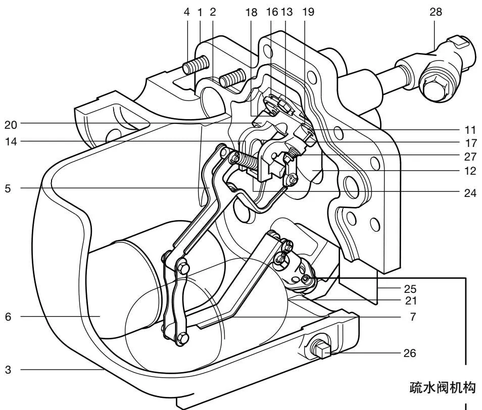
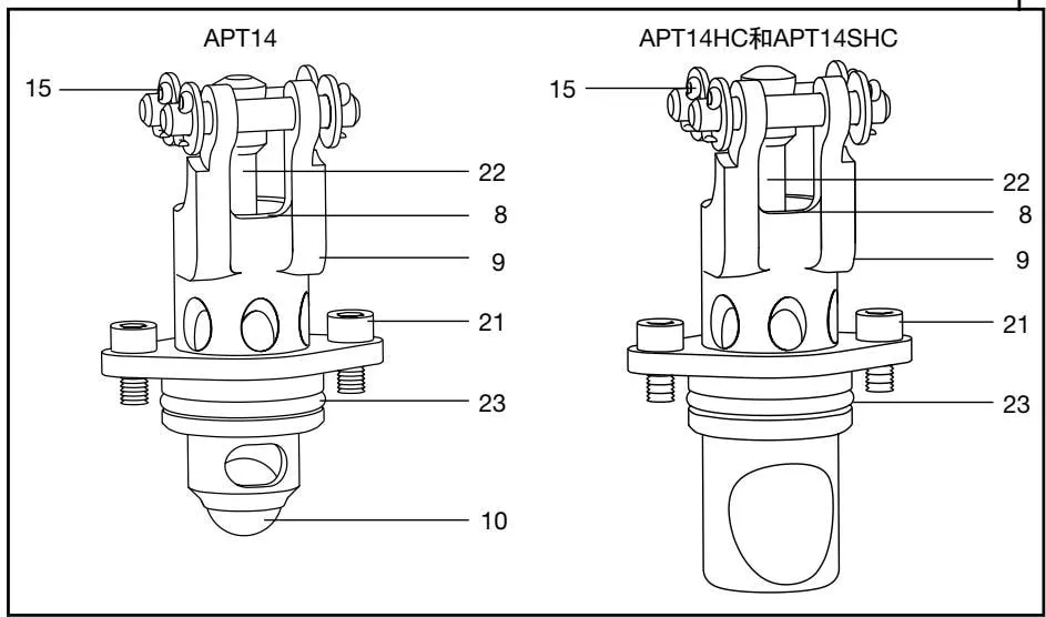
Figure 3
3. Operation
Step 1 (Figure 4)
The APT14, APT14HC and APT14SHC automatic pump traps operate on the positive displacement principle. Condensate enters the pump body through the swing check valve, causing the float to rise. The float is connected to the steam trap mechanism by a linkage shaft. When the upstream system pressure PS is sufficient to overcome the back pressure PB (Figure 4), the accumulated condensate is discharged through the open second-stage steam trap mechanism. Under these conditions, the float automatically responds to the amount of condensate entering the APT14 and controls the opening and closing of the steam trap.
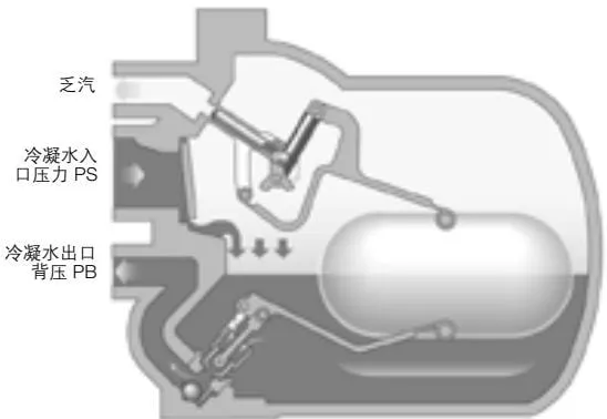
Figure 4 APT14
Step 2 (Figure 5)
With some temperature-controlled equipment, the system pressure PS may be lower than the back pressure PB (Figure 5).
In this situation, a standard steam trap cannot discharge the condensate, causing the equipment to become flooded.
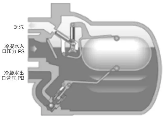
Figure 5 APT14
Step 3 (Figure 6)
With the APT14, APT14HC and APT14SHC, however, condensate fills the pump body and raises the float until it operates the changeover linkage, opening the motive steam inlet and closing the exhaust valve.
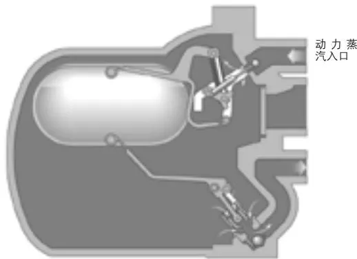
Figure 6 APT14
Step 4 (Figure 7)
The snap-action mechanism rapidly changes the operating mode from steam trap mode to power pump mode.
As the motive steam inlet valve opens, the pressure inside the APT14, APT14HC and APT14SHC rises above the back pressure, forcing condensate from the steam trap seat into the condensate recovery system.
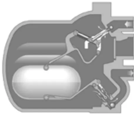
Motive steam inlet
Figure 7 APT14
Step 5 (Figure 8)
As the condensate level in the pump body falls, the float operates the changeover linkage again, closing the motive steam inlet and opening the exhaust valve.
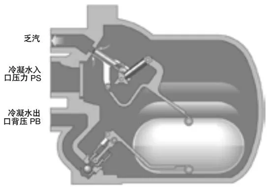
Figure 8 APT14
Step 6 (Figure 9)
When the exhaust valve opens, the pressure inside the APT14, APT14HC and APT14SHC balances with the condensate inlet pressure, and condensate re-enters through the inlet swing check valve. At the same time, the outlet ball check valve closes, preventing condensate from flowing back into the pump body. The steam trap and pumping cycle then recommences.
Note: The APT14HC and APT14SHC require a Spirax Sarco DN40 wafer check valve to be installed between the condensate outlet flanges.
Return to Step 1.
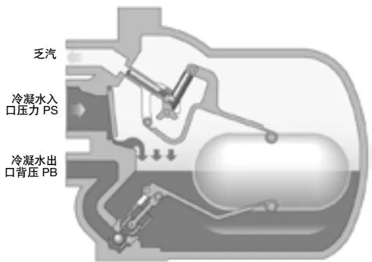
Figure 9 APT14
4. Installation
Important - Safety information
Before carrying out any installation or maintenance, read the instructions in Section 1.12 concerning the lifting of this product.
Before carrying out any installation or maintenance, ensure that all steam and condensate lines are isolated.
Ensure that any residual pressure in the product or connected pipework has been fully released, and that all hot components have cooled to prevent burns. Wear suitable protective clothing before carrying out any installation or maintenance work.
Note: If the pump handles an explosive medium, the motive gas must be inert and non-oxidising.
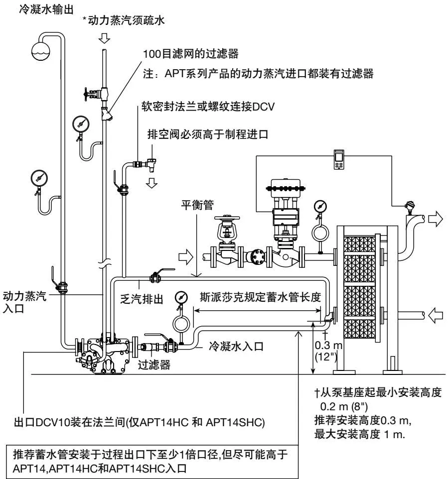
Figure 10
4.1 Inlet pipework
To prevent waterlogging of the equipment, the condensate volume generated by the pump during the draining cycle should be considered when selecting the inlet pipe size. Normally, a pipe length and diameter providing a condensate volume of 4 L (APT14) and 8 L (APT14HC and APT14SHC) is sufficient. It is recommended that the condensate collection pipe be positioned at least one pipe diameter below the process outlet, but as high as possible above the APT inlet. A Spirax Sarco Y-type strainer must be installed at the condensate inlet of the APT14, APT14HC and APT14SHC, as shown in Figure 11.
4.2 Recommended installation height
The recommended installation height is at least 0.3 m. The minimum installation height is 0.2 m, but the capacity will be reduced. The maximum installation height is 1 m.
Note: During cold start-up, liquid surging may occur at the inlet check valve. In this case, it is recommended that a throttling valve be installed to reduce the filling pressure.
4.3 Connections (see Figure 11)
The APT has four connections: the DN40 (1-1/2”) connection (APT14) or DN50 (2”) connection (APT14HC and APT14SHC) is connected to the equipment drain outlet; the DN25 (1”) connection (APT14) or DN40 (1-1/2”) connection (APT14HC and APT14SHC) is connected to the condensate recovery pipework. Flow direction arrows indicate the correct flow direction. The DN15 (1/2”) connection marked (S) is connected to the drained motive steam pipework. To ensure that this pipe remains drained at all times, a Spirax Sarco steam trap and a 100 mesh strainer must be installed (see Figure 10). The DN15 (1/2”) connection marked (E) is connected to the equipment condensate outlet through a balance pipe. The balance pipe should be connected as close as possible to the equipment condensate outlet and to the top of the condensate pipe, as shown in Figure 10.
Note: If a high-temperature shut-off device is installed on the heat exchanger to prevent overheating, it must be installed upstream of the control valve and the APT motive steam take-off point.
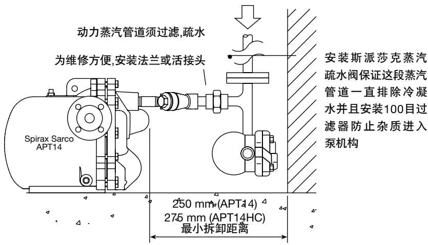
Figure 11 Recommended connection of motive steam and system pipework
4.4 Outlet pipework
Correct selection of the outlet pipe size is essential to prevent excessive backpressure in the APT14, APT14HC and APT14SHC. The selection must take into account the flash steam quantity when the heat exchanger is operating at full load, as well as the condensate discharged by other equipment into the same recovery pipe.
Note: For the APT14HC and APT14SHC, a Spirax Sarco DN40 DCV10 check valve must be installed between the pump body outlet flange and the pipe flange. Ensure that the DCV10 is installed centrally, that the flow direction arrow points in the correct direction, and that a gasket is installed on both sides of the check valve.
For detailed information, refer to IM-P601-32.
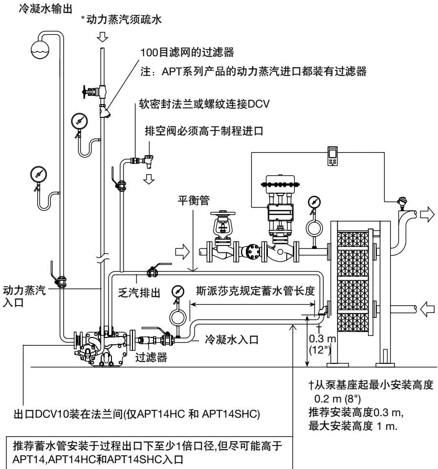
Figure 12