
- Safety information
- Product information
- Installation
- Commissioning
- Operation
- Maintenance
- Spare parts
1. Safety information
Correct installation, commissioning, and maintenance by professionally qualified personnel in accordance with the operating instructions are the only guarantees for safe operation of this product (see Section 1.11). After installation, the installation and safety guidelines for the piping system and plant construction, the correct use of tools, and the provision of necessary safety equipment must be observed.
1.1 Intended use
Refer to the Installation and Maintenance Instructions, nameplate, and technical documentation to ensure that the product is suitable for the intended application. This product complies with the requirements of the European Pressure Equipment Directive 97/23/EC and can be supplied with the CE mark where required.
i) The product is designed for Group2 fluids under the Pressure Equipment Directive, including steam, air, and water/condensate. For use with other fluids, consult Spirax Sarco.
ii) Ensure that the materials are suitable for the operating conditions and that the maximum/minimum system pressure and temperature are within the product’s design range. If the product’s maximum operating range is lower than the system operating conditions, or if product failure could result in overpressure or overheating, install safety devices to address the potential hazard.
iii) Ensure that the product is installed correctly and that the inlet and outlet are not reversed.
iv) Spirax Sarco products are not designed to withstand external stresses. Installers must ensure that external forces from the system do not act on the product.
v) Before installing the product in a steam or other high-temperature system, remove the protective covers from all product connections and the protective film from the nameplate.
1.2 Accessibility
After installation, ensure that there is sufficient operating space. Where necessary, prepare a safe working platform before operating the product. Provide lifting equipment where required.
1.3 Lighting
Ensure adequate lighting, particularly when carrying out detailed or complex work.
1.4 Hazardous fluids or gases in the pipeline
Consider in advance which fluids are present in the pipeline or may have been present in it. Take care with flammable substances, substances hazardous to health, and high- or low-temperature substances.
1.5 Hazardous working environment
Explosion risk, oxygen deficiency (for example, inside tanks or in low-lying areas), hazardous gases, high or low temperatures, hot surfaces, fire hazards (for example, during welding), excessive noise, and moving machinery.
1.6 The system
Understand the operation of the complete system. Before carrying out any operation (such as closing an isolation valve or operating an electrical switch), consider whether it could place other parts of the system or other personnel at risk.
Hazards include isolated ventilation ducts or protective devices and failed control or alarm devices. Open and close isolation valves slowly to prevent system shock.
1.7 Pressure systems
Ensure that system pressure is isolated or completely vented. Consider isolating the system with double isolation valves and locking or tagging the closed valves. Never assume that a pressure gauge reading of zero means that the system has been completely depressurized.
1.8 Temperature
After isolating the product, allow it to cool to room temperature to prevent burns.
1.9 Tools and spare parts
Before operation, ensure that suitable tools and spare parts are available. Only use genuine Spirax Sarco spare parts.
1.10 Protective clothing
Consider whether operators or nearby personnel should wear protective clothing to protect against hazards such as chemicals, high or low temperatures, radiation, noise, falling objects, and eye or facial injuries.
1.11 Permits to work
All work must be carried out by competent personnel or under their supervision. Installation and operating personnel must be trained in accordance with the product’s Installation and Maintenance Instructions so that they can use the product correctly.
Where a permit-to-work system is in operation, operators must comply with it. Where no such system is in operation, the person responsible must understand the nature of the work and provide a safety assistant where necessary.
Post warning notices where necessary.
1.12 Handling
Manual handling of large or heavy products presents a risk of injury. Lifting, pushing, pulling, carrying, or supporting heavy loads with the body can cause injury, particularly back injuries. It is recommended that the workload, individual capabilities, load, and working environment be considered, and that suitable handling methods be adopted according to site conditions.
1.13 Residual heat
During normal use, the external surfaces of this product may become very hot. When operated at the maximum permitted operating temperature, the product surface temperature may reach 300°C (572°F).
This product is not self-draining. Take care when removing or moving it from its installed position (refer to the Maintenance Instructions).
1.14 Freezing
For non-self-draining products used in ambient temperatures below freezing, suitable protection against frost must be provided.
1.15 Disposal
Unless otherwise stated in the Installation and Maintenance Instructions, this product is recyclable and presents no ecological hazard when disposed of properly.
1.16 Returning products
In accordance with EC health, safety, and environmental legislation, when returning products, customers and resellers must provide hazard information and carefully handle any residual contaminants or mechanical damage that could cause health, safety, or environmental hazards. Hazard information must be provided in writing, including safety data sheets identifying any known or potential hazards.
1.17 Safety precautions for cast iron products in steam systems
Cast iron products are widely used in steam and condensate systems. When installed and used in accordance with correct steam engineering practices, they are very safe. However, because of its mechanical properties, cast iron is more susceptible to deformation than other materials such as ductile iron and stainless steel. The following guidelines help prevent waterhammer and ensure safe operation of steam systems.
Safe operation
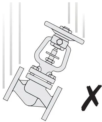
Cast iron is a brittle material. If a product is dropped from a height during installation, it must be fully inspected and pressure tested to confirm that there is no risk of damage before being returned to service.
Preventing waterhammer
Draining the steam main:
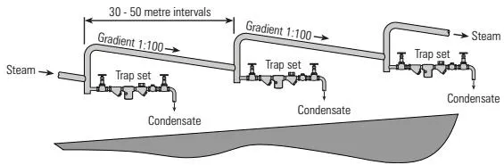
Steam main recommendations and restrictions: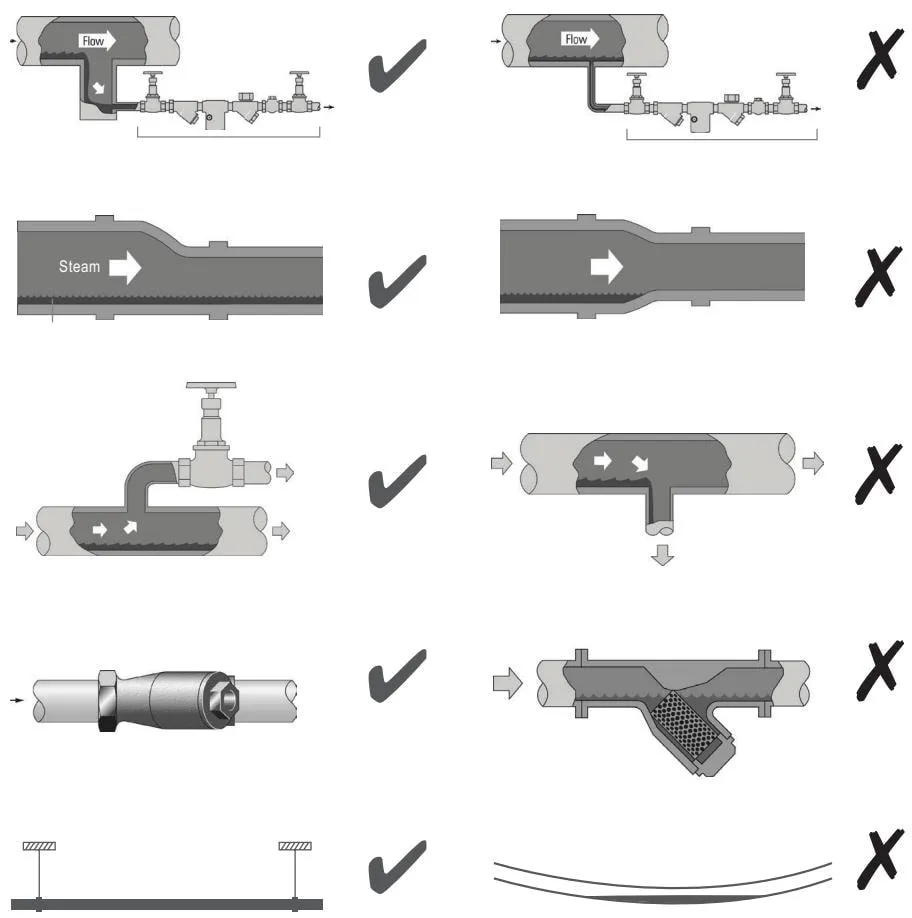
Preventing tensile stress
Incorrect pipe connection:
Reinstallation after initial installation or maintenance:


Avoid overtightening
Use the correct torque values
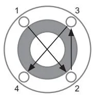
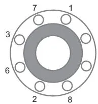
Flange connection bolts must be tightened in the sequence shown
to ensure balanced bolt loading and a tight connection
Thermal expansion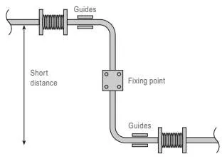
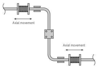
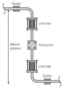
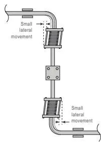
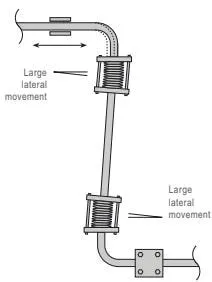
2. Product information
Introduction
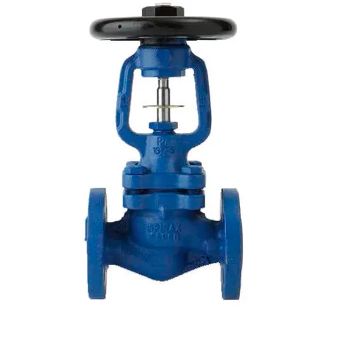
Bellows-sealed globe valves with PN16, PN25 and PN40 flanged connections, suitable for steam, gases, liquids, condensate and water systems.
Note: Throttling trim, soft seats (DN100 and below) and balanced trim (PN125 and above) are available for certain special applications.
Options
| Standard parabolic plug | Throttling plug and locking device | Balanced plug | Standard plug with R-PTFE soft seat | Throttling plug with R-PTFE soft seat | Bellows | |||
| Single bellows | Double bellows | |||||||
| BSA1 | ● | ● | ||||||
| BSA1T | ● | ● | ||||||
| BSA1RPTFE | ● | ● | ||||||
| BSAY1TRPTFE | ● | ● | ||||||
| BSA1B/D | ● | ● | ||||||
| BSA2 | PN16 | ● | ● | |||||
| PN25 | ●† | ● | ||||||
| BSA2T | PN16 | ● | ● | |||||
| PN25 | ● | ● | ||||||
| BSA2RPTFE | PN16 | ● | ● | |||||
| BSA2TRPTFE | PN16 | ● | ● | |||||
| PN25 | ● | ● | ||||||
| BSA2B/D | ● | ● | ||||||
| BSA3 | ●† | ● | ||||||
| BSA3T | ● | ● | ||||||
| BSA3RPTFE | ● | ● | ||||||
| BSA3TRPTFE | ● | ● | ||||||
| BSA3B/D | ● | ● | ||||||
†DN125 and above
Standards
This product complies with the European Pressure Equipment Directive 97/23/EC. A CE mark can be provided on request.
Certificates
EN 10204 2.2 certificates are available for BSA1 and BSA1T. EN 10204 3.1 certificates are available for BSA2, BSA2T, BSA3 and BSA3T.
Note: Please specify the required certificate when placing the order.
Note: For further information, refer to technical data sheets TI-P137-18 and TI-P137-19.
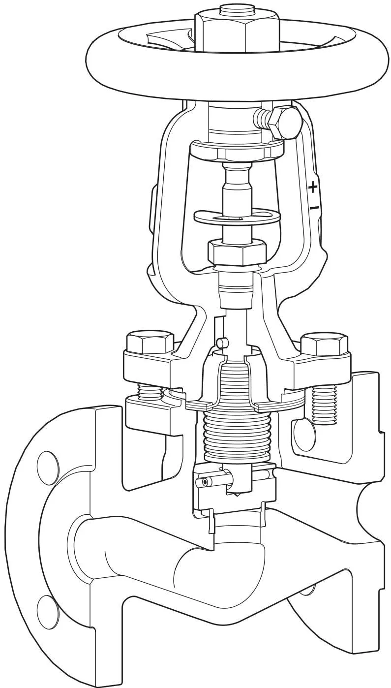
Figure 1 BSAT illustration
Throttling Plug Travel Limitation
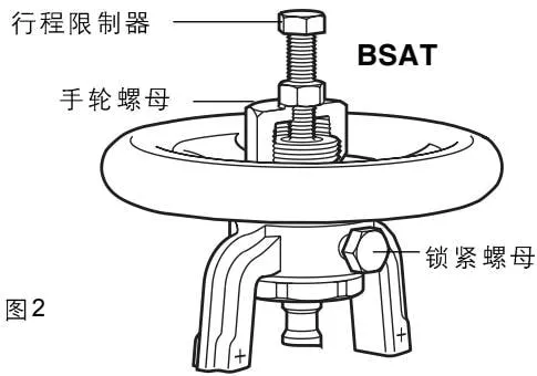
Figure 2
The handwheel nuts on BSA1T, BSA2T and BSA3T have a threaded hole for installing a travel limiter. Customers can select bolts according to the dimensions listed in the table below.
| Size | Hexagon bolt |
|---|---|
| DN15 - DN80 | M8 x 50 mm |
| DN100 - DN150 | M12 x 75 mm |
| DN200 - DN250 | M12 x 100 mm |
Flange Gasket Sealing Assembly Options
(Only applicable to BSA3 ANSI 1/2” - 4”)
Figure 3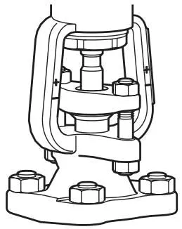
Balanced plug option
Figure 4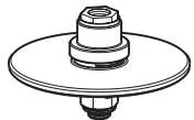
DN150 shown
| | | | | ----------- | ---------------- | --------------- | --- | | | colspan=“2” | 25 bar ΔP DN125 | | rowspan=“3” | For greater than | 17 bar ΔP DN150 | 6” | | | 10 bar ΔP DN200 | 8” | | | 6 bar ΔP DN250 | (BSA2 only) |
Soft plug option
Figure 5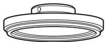
2.2 Size and Pipe Connections
2.2.1 BSA1 and BSA1T
DN15, 20, 25, 32, 40, 50, 65, 80, 100, 125, 150 and 200
Flanges 1092 / ISO 7005 PN16 and JIS B 2210 / KS B 1511 10K
Face-to-face dimensions EN 558
2.2.2 BSA2 and BSA2T
DN15, 20, 25, 32, 40, 50, 65, 80, 100, 125, 150, 200 and 250^* (PN25 only)
Flanges EN 1092 / ISO 7005 PN16 and PN25
Face-to-face dimensions EN 558
2.2.3 BSA3 and BSA3T (DIN)
DN15, 20, 25, 32, 40, 50, 65, 80, 100, 125, 150 and 200
Flanges EN 1092 / ISO 7005 PN40 (DN15 - DN150)
Flanges EN 1092 / ISO 7005 PN25 (DN200)
Face-to-face dimensions EN 558
2.2.4 BSA3 and BSA3T (ANSI)
Size 1/2 , 3/4 , 1”, 11/2 , 2”, 3”, 4”, 6” * and 8” * (*ANSI 300 only)
Flanges ANSI B 16.5 / BS 1560 Class 150 and 300 and JIS B 2210 / KS B 1511 20K
Face-to-face dimensions ANSI B 16.10
2.3 Product Limitations
See Section 2.4 for BSA1 and BSA1T.
See Section 2.6 for BSA3 and BSA3T (DIN).
See Section 2.5 for BSA2 and BSA2T.
See Section 2.7 for BSA3 and BSA3T (ANSI).
Note: Maximum permissible pressure drop when BSA-T models are used for throttling control.
| DN15 - DN80 | 2.0 bar | (29.00 psi) |
|---|---|---|
| DN100 - DN125 | 1.5 bar | (21.75 psi) |
| DN150 | 1.0 bar | (14.50 psi) |
| DN200 - DN250 | 0.8 bar | (11.60 psi) |
2.4 Operating Range - BSA1 and BSA1T
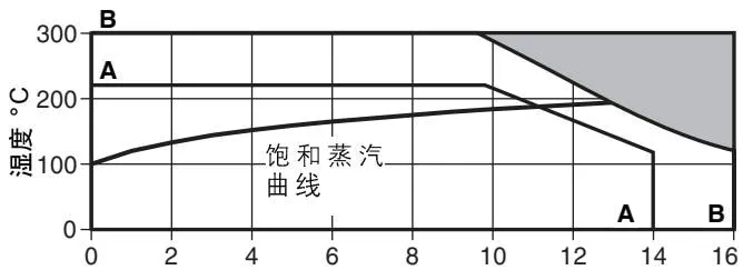
Pressure barg
This product must not be used in this area
A - A Flange connection JIS / KS 10K
B-B Flange connection PN16
| | | PN16 | JIS / KS 10K | | ----------------------- | ----------------------------------------------------- | ------------------- | ------------ | ----- | | colspan=“2” | Valve body design conditions | PN16 | JIS / KS 10K | | colspan=“2” | PMA - Maximum allowable pressure | 16 bar g | 14 bar g | | colspan=“2” | TMA - Maximum allowable temperature | 300°C | 220°C | | colspan=“2” | PMO - Maximum operating pressure with saturated steam | 12.9 bar g | 11 bar g | | rowspan=“2” | TMO - Maximum operating temperature | Soft seat | 230°C | 220°C | | | Metal seat | 300°C | 220°C | | colspan=“2” | Minimum operating temperature | -10°C | -10°C | | rowspan=“2” colspan=“2” | △PMX - Maximum allowable differential pressure | BSA1 | Same as PMO | | | BSA1T | Same as Section 2.3 | | | colspan=“2” | Design maximum cold hydraulic test pressure | 24 bar g | 20 bar g |
2.5 Operating Range - BSA2 and BSA2T
PN16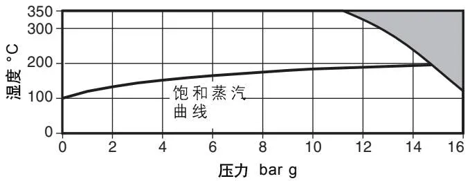
PN25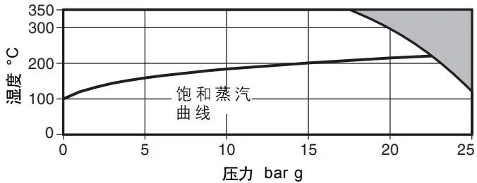

This product must not be used in this area
| | | PN16 | PN25 | | ----------------------- | ----------------------------------------------------- | ------------------- | ----------- | ----- | | colspan=“2” | Valve body design conditions | PN16 | PN25 | | colspan=“2” | PMA - Maximum allowable pressure | 16 bar g | 25 bar g | | colspan=“2” | TMA - Maximum allowable temperature | 350°C | 350°C | | colspan=“2” | PMO - Maximum operating pressure with saturated steam | 14.7 bar g | 22.3 bar g | | rowspan=“2” | TMO - Maximum operating temperature | Soft seat | 230°C | 230°C | | | Metal seat | 350°C | 350°C | | colspan=“2” | Minimum operating temperature | -10°C | -10°C | | rowspan=“2” colspan=“2” | △PMX | BSA2 | Same as PMO | | | BSA2T | Same as Section 2.3 | | | colspan=“2” | Design maximum cold hydraulic test pressure | 24 bar g | 38 bar g |
2.6 Operating Range - BSA3 and BSA3T (DIN)
PN25, DN200
PN40, DN15 - DN150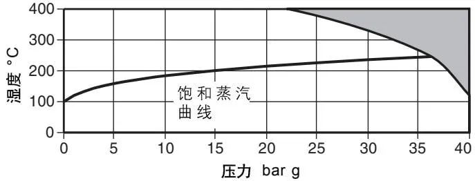

This product must not be used in this area
| | | PN25,PN200 | PN40,DN15-DN150 | | ----------------------- | ----------------------------------------------------- | ------------------- | --------------- | ----- | | colspan=“2” | Valve body design conditions | PN25,PN200 | PN40,DN15-DN150 | | colspan=“2” | PMA - Maximum allowable pressure | 25 bar g | 40 bar g | | colspan=“2” | TMA - Maximum allowable temperature | 400°C | 400°C | | colspan=“2” | PMO - Maximum operating pressure with saturated steam | 23.2 bar g | 27 bar g | | rowspan=“2” | TMO - Maximum operating temperature | Soft seat | 230°C | 230°C | | | Metal seat | 400°C | 400°C | | colspan=“2” | Minimum operating temperature | -10°C | -10°C | | rowspan=“2” colspan=“2” | △PMX - Maximum allowable differential pressure | BSA3 | Same as PMO | | | BSA3T | Same as Section 2.3 | | | colspan=“2” | Design maximum cold hydraulic test pressure | 38 bar g | 60 bar g |
2.7 Working Range - BSA3 and BSA3T (ANSI)
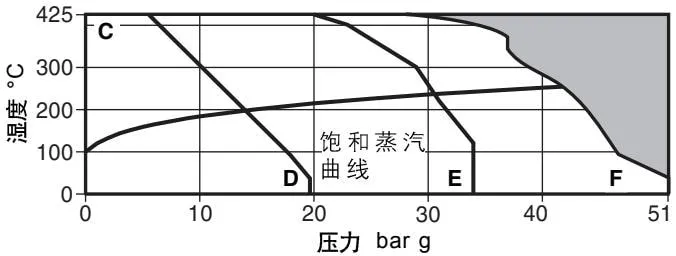

This product must not be used in these areas
C - D Flanged ANSI 150
C - E Flanged JIS / KS 20K
C - F Flanged ANSI 300
| Valve body design conditions | ANSI150 | ANSI300 | JIS/KS 20K | | ------------------------------------ | ---------------------------------------------------- | ----------------- | ------------------- | ----------- | | PMA - Maximum allowable pressure | 51 bar g | 51 bar g | 51 bar g | | TMA - Maximum allowable temperature | 425°C | 425°C | 425°C | | rowspan=“2” | PMO - Maximum operating pressure for saturated steam | Soft seat 14bar g | 27bar g | 27bar g | | | Metal seat 14 bar g | 30.7bar g | 41.6 bar g | | rowspan=“2” | TMO - Maximum operating temperature | Soft seat 230°C | 230°C | 230°C | | | Metal seat 425°C | 425°C | 425°C | | Minimum operating temperature | 0°C | 0°C | 0°C | | rowspan=“2” | △PMX - Maximum allowable differential pressure | | BSA3 | Same as PMO | | | | BSA3T | Same as Section 2.3 | | Maximum cold hydraulic test pressure | 31 bar g | 77 bar g | 50 bar g |
3. Installation
Note: Before installation, carefully read the safety information in Section 1.
Before installation, check the installation and maintenance instructions, name-plate and technical data to confirm that the product is suitable.
3.1 Check the materials, pressure and temperature, including their maximum values, to ensure that the maximum operating limits are not lower than the system conditions. The system should also include safety devices to prevent overpressure.
3.2 Remove the protective covers from the connections.
3.3 Install the isolation valve in the direction indicated by the arrow on the valve body. The valve stem should preferably be vertical. The valve can be installed in either a horizontal or vertical pipeline. (See Figure 7 on page 11 for details.)
3.4 Important: When a balance valve core is installed, the valve must be installed so that the upstream fluid enters the upper chamber of the valve body first, allowing the fluid pressure to act on the upper part of the balance valve core. This is opposite to the normal installation direction. If a balance valve core is replaced or installed on a standard valve, reverse the valve flow direction by 180° and mark a new flow arrow on the valve body to indicate the new flow direction.
The valve must not be installed upside down.
What is a balance valve core, and how does it work?
- The balance valve core is a two-stage switching system.
- (See Figure 6.) The small valve (A) acts as a pilot valve and opens first during operation, allowing fluid to enter the downstream side at a controlled rate. The pressure differential between the upstream and downstream sides of the valve gradually decreases, allowing the main valve to lift easily from its seat. To help the valve close, the fluid should first flow into the upper valve chamber, which is opposite to the normal flow direction.
3.6 Open the isolation valve slowly to prevent system vibration.
3.7 Note: When maintenance is carried out downstream of the isolation valve, two isolation valves should be installed, with a drain valve fitted between them, to ensure safety. If this valve is the last valve on the pipeline, a blind flange should be installed at the valve outlet for safety reasons.
- This arrangement is mainly used to assist the closing of large-size valves. For large-size isolation valves or isolation valves operating at a high differential pressure, the normal flow direction can make the valve difficult to close. Reversing the flow direction and installing a small valve (A) solves this problem.
For valves of different sizes, a balance valve core must be used when the upstream-to-downstream pressure differential exceeds the values listed in the table below; otherwise, the valve cannot close.
3.5 In steam system pipework, install a steam trap close to the valve on the upstream side to ensure that condensate in the pipework can drain properly when the valve is closed and to prevent water hammer from damaging the valve. A float or thermodynamic steam trap can be selected. The steam traps throughout the steam system pipework are equally important.
| Size | Differential pressure (bar) |
|---|---|
| DN125 | 25.0 |
| DN150 | 17.0 |
| DN175 | 13.0 |
| DN200 | 10.0 |
| DN250 | 6.0 |
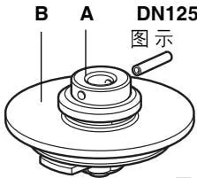
Figure 6
4. Commissioning
After installation or maintenance, ensure that the system functions correctly by first testing the alarm or protective devices.
5. Operation
5.1 Bellows-sealed globe valves eliminate the leakage commonly associated with stem packing seals, making an important contribution to energy conservation.
5.2 The valve is manually operated by the handwheel. During operation, pay close attention to the correct direction of stem movement.
To fully open the valve, turn the handwheel to raise the stem to its highest position (the valve position indicator on the stem aligns with the ”+” mark on the bonnet), then turn the handwheel clockwise by 1/8 to 1/4 turn to eliminate backlash. This also prevents damage to the stem, bellows, and other components caused by attempting to force the valve open when it is already fully open. All Spirax Sarco bellows-sealed globe valves (BSA&BSAT) have two position indicators on the stem (”+” indicates that the valve is fully open; ”-” indicates that the valve is fully closed).
5.3 When operating the valve with a handle, take care not to apply excessive force, as this may cause permanent damage to the valve.
5.4 BSAT models are fitted with a throttling trim for flow control. The number of handwheel turns affects the flow rate. Once the required flow rate has been achieved, tighten the locking screw and stroke limiter (see Fig. 8 on page 12). This reduces valve vibration. The relationship between the number of handwheel turns and the flow rate for each valve size is shown on page 12.
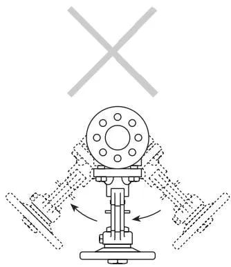
Fig. 7 Incorrect installation
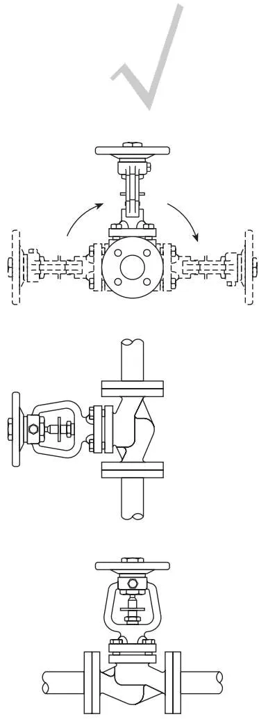
Correct installation
BSAT flow parameters
Flow parameters at different numbers of opening turns for each valve size
| Size | 15 | 20 | 25 | 32 | 40 | 50 | 65 | 80 | 100 | 125 | 150 | 200 | 250 |
|---|---|---|---|---|---|---|---|---|---|---|---|---|---|
| Handwheel turns | colspan=“13” | Kv values corresponding to the number of handwheel turns. Test standard EN 60534-2-3, water temperature 20°C | |||||||||||
| 0 | 0 | 0 | 0 | 0 | 0 | 0 | 0 | 0 | 0 | 0 | 0 | 0 | 0 |
| 0.5 | 1.2 | 1.2 | 1.4 | 2.2 | 4.4 | 4.1 | 5.6 | 10.4 | 12.0 | 21 | 28 | 66 | 110 |
| 1 | 1.7 | 1.7 | 2.0 | 3.7 | 5.0 | 5.0 | 7.0 | 11.5 | 14.3 | 23 | 30 | 81 | 140 |
| 1.5 | 2.7 | 2.9 | 2.9 | 5.0 | 5.5 | 6.0 | 9.2 | 13.6 | 24.5 | 26 | 33 | 97 | 150 |
| 2 | 3.6 | 4.0 | 4.6 | 7.9 | 7.6 | 7.2 | 11.6 | 16.3 | 34.1 | 42 | 46 | 111 | 165 |
| 2.5 | 4.4 | 5.3 | 6.4 | 10.6 | 11.0 | 9.7 | 12.4 | 18.5 | 59.6 | 67 | 65 | 149 | 190 |
| 3 | 5.4 | 6.6 | 8.5 | 13.8 | 14.7 | 14.1 | 13.0 | 21.1 | 86.2 | 94 | 90 | 199 | 225 |
| 4 | 10.6 | 17.0 | 22.6 | 24.4 | 25.2 | 24.5 | 123.0 | 140 | 152 | 302 | 330 | ||
| 4.5 | 11.2 | 18.3 | 24.4 | 29.4 | 32.5 | 29.0 | 139.0 | 181 | 177 | 355 | 451 | ||
| 5 | 11.9 | 19.6 | 27.2 | 37.0 | 43.6 | 39.1 | 164.1 | 185 | 216 | 403 | 460 | ||
| 6 | 28.9 | 46.2 | 60.2 | 61.0 | 179.0 | 220 | 264 | 455 | 600 | ||||
| 6.5 | 29.1 | 47.0 | 63.0 | 69.0 | 186.0 | 230 | 288 | 480 | 641 | ||||
| 6.7 | 29.3 | 47.2 | 64.3 | 73.0 | 235 | 293 | 487 | 656 | |||||
| 7 | 65.9 | 78.0 | 241 | 305 | 495 | 678 | |||||||
| 8 | 71.2 | 90.0 | 259 | 337 | 507 | 738 | |||||||
| 8.5 | 74.6 | 92.0 | 348 | 522 | 760 | ||||||||
| 9.5 | 99.0 | 369 | 793 | ||||||||||
| 10 | 101.6 | 805 | |||||||||||
| 10.7 | 827 |
The handwheels of BSA1T, BSA2T, and BSA3T throttling trims have a threaded hole for installing a stroke limiter. Customers can select the stroke limiter bolt according to the dimensions in the table below.
| Size | Hex bolt |
|---|---|
| DN15 - DN80 | M8 x 50 mm |
| DN100 - DN150 | M12 x 75 mm |
| DN200 - DN250 | M12 x 100 mm |
Note: The maximum allowable pressure drop during throttling control is
| DN15 - DN80 | 2.0 bar |
|---|---|
| DN100 - DN125 | 1.5 bar |
| DN150 | 1.0 bar |
| DN200 - DN250 | 0.8 bar |
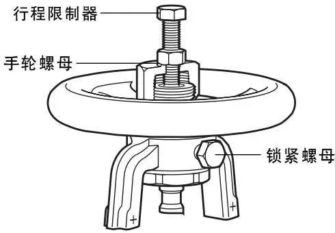
Fig. 8
6. Maintenance
All internal parts of the bellows-sealed stop valve are replaceable (see Section 7, Spare parts).
Note: Before carrying out maintenance, carefully read the safety information in Section 1.
Warning: The valve body gaskets (10a and 10b) contain thin stainless steel support rings, which may cause personal injury if handled carelessly.
6.1 Before carrying out any operation, confirm that the valve has been isolated from the pressurized system and that the pressure inside the valve has been fully released to atmosphere. Allow sufficient time for the valve to cool. When reassembling, ensure that all contact surfaces are clean.
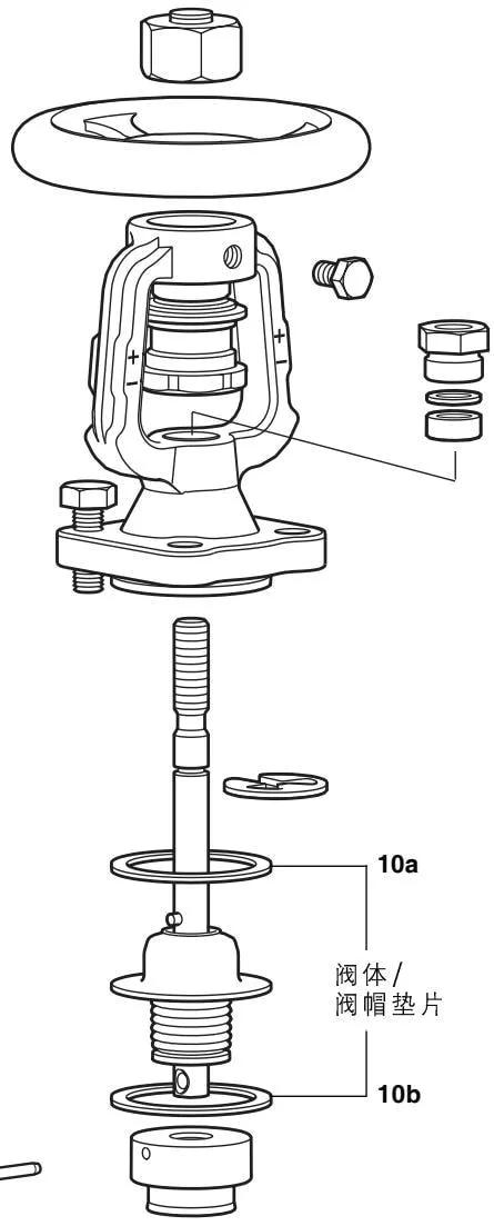
Figure 9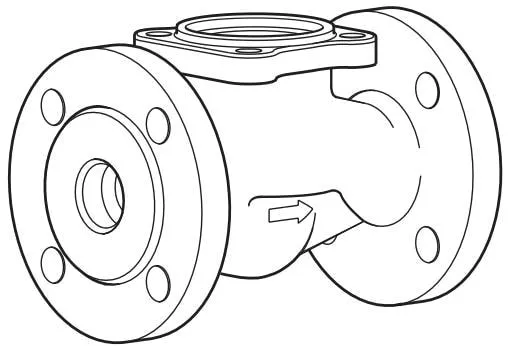
6.2 How to install the valve body/bonnet gaskets
The valve body/bonnet gaskets can be installed directly on the pipeline without removing the valve. Remove the bonnet (2) from the valve body (1) to access the valve body gasket (10b), which can then be replaced quickly. Ensure that the gasket surfaces are clean before replacement.
To replace the second gasket (10a), located between the bonnet and the stainless steel bellows support ring, first remove the valve position indicator. For BSAT models, remove the locking screw. Turn the handwheel (7) clockwise. This will push the main valve stem downward, creating a gap between the bellows support ring and the bonnet. If the support ring remains close to the bonnet (2), carefully prise up the collar, taking care not to damage it.
Do not stretch the bellows, as this will affect their service life.
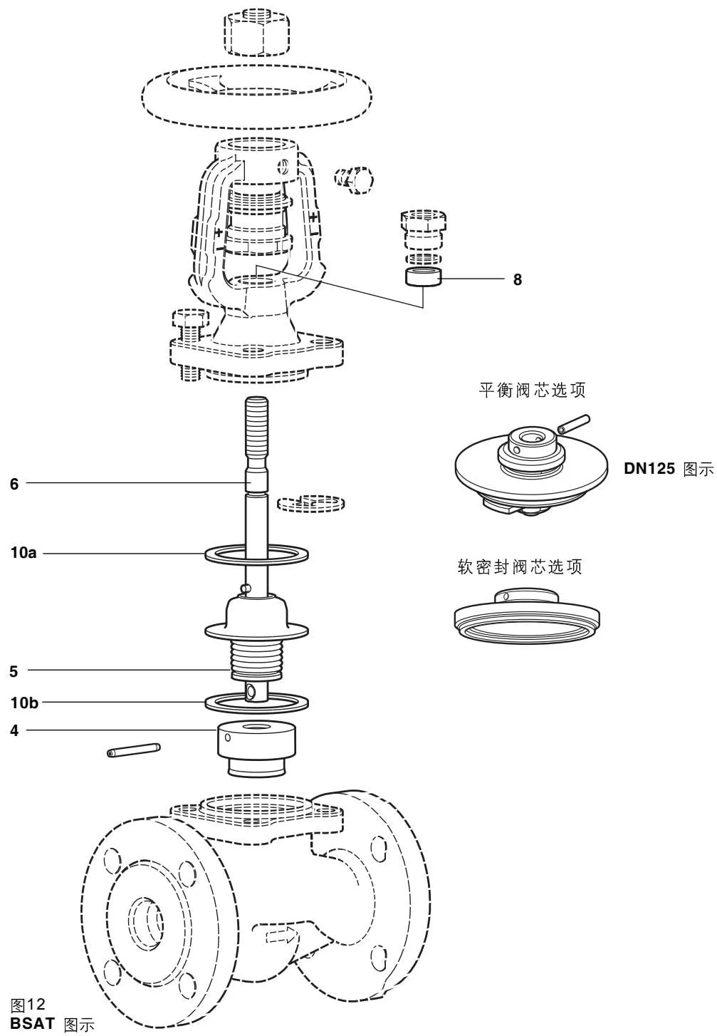
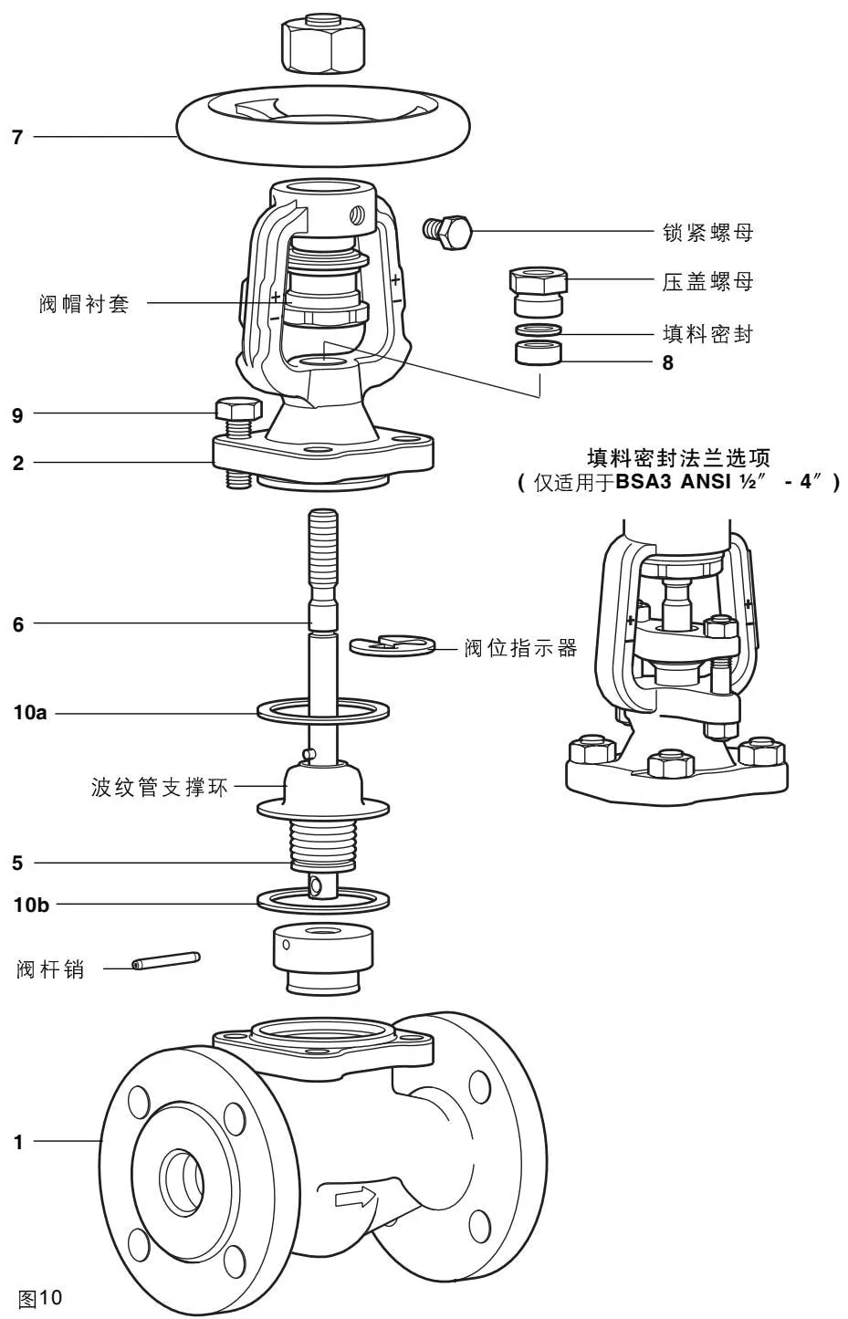
Continue turning the handwheel (7) clockwise until the stem unscrews from the bonnet bush. Once the stem has separated from the bonnet bush, remove the gland nut (or, for flanged versions, the gland flange) and gasket (or gland follower) and place them safely aside. These parts are not supplied as spare parts. The stem/bellows assembly (6, 5) can now be removed from the bonnet. Replace the second bellows gasket (10a), ensuring that the bellows support ring and bonnet surfaces are clean and that the gasket is positioned correctly. Replace the stem seal ring (8) when reassembling the stem/bellows assembly (6, 5) (see Section 6.3).
6.3 How to install the stem seal
Continue the procedure in Section 6.2. The stem seal ring (8) can now be replaced. Two seal rings are normally supplied, but only one is required for the actual application. Ensure that all old stem sealing material has been removed from the bonnet cavity and check that the surface is clean. Installation is the reverse of removal. Remember to place a new bellows sealing gasket between the bellows and the bonnet. Ensure that the stem pin (embedded in the stem) is aligned with the bonnet groove. Before screwing the end of the stem into the bonnet bush, remember to install a new stem seal ring (8). Take care not to damage the inner surface of the seal ring with the stem threads. Carefully slide the new seal ring over the stem into the recess at the bottom, then slide the gland gasket (or gland follower) onto the top of the seal ring. Remember to tighten the seal ring once the valve has been fully assembled.
6.4 How to install the stem/bellows assembly
Continue the procedure in Section 6.2 to replace the stem/bellows assembly (6, 5). Installation is the reverse of removal. Remember to install the second bellows gasket (10a) between the bellows collar and the bonnet, ensuring that the bellows sealing gasket (10a) is correctly positioned. Before installing the new stem/bellows assembly, apply a small amount of lubricant, such as GULF Sovereign lubricant, to the end of the stem retaining pin, which will be pressed into the stem. Carefully insert the stem into the bonnet. Before screwing the stem into the bonnet bush, remember to install a new stem seal ring (8) (see Section 6.3), the gland gasket and the gland nut. Take care not to damage the inner surface of the seal ring with the stem threads. Carefully slide the new seal ring over the stem into the recess at the bottom, then slide the gland gasket (or gland follower) onto the top of the seal ring. Remember to tighten the seal ring once the valve has been fully assembled.
6.5 How to install the valve disc
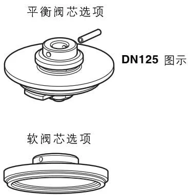
Continue the procedure in Section 6.2 to replace the valve disc. The valve disc (4), or balancing disc assembly, can be replaced simply by removing the old locating pin and inserting the new locating pin supplied into the new disc. If the disc is secured with a lock-nut and collet assembly, prise the skirt away from the lock-nut and collet so that the nut can rotate. Remove the collet and lock-nut, and keep them safely aside, as they are not supplied as spare parts. Installation is the reverse of removal. Apply a small amount of lubricant, such as molybdenum disulphide lubricant, to the collet and threads.
When installing a new disc, tighten the nut and then flatten the skirt beside the nut to secure it. If the original disc is reused, a new metal skirt must be fitted.
Important note
When a balancing disc is installed, the valve must be installed so that the upstream fluid first enters the upper chamber of the valve body, allowing the fluid pressure to act on the upper surface of the balancing disc. This is the opposite of the usual installation direction. If a standard disc is replaced with a balancing disc, the valve body must be rotated through 180° during installation, and a new flow arrow must be marked on the valve body to indicate the changed flow direction.
6.6 Final assembly
After ensuring that the bellows collar and gaskets (10a, 10b) are correctly positioned and aligned with the bonnet, complete the final installation of the valve body (1). Tighten the bonnet nuts and bolts (9) evenly.
Handwheel
The handwheel is not supplied as a spare part. Loosen the locking nut on the handwheel clockwise to remove the handwheel. Note: The thread on the handwheel nut is left-handed, so the nut must be loosened by turning it clockwise. Place a suitable spanner (Spirax Sarco provides detailed drawings) over the bonnet bush and remove the handwheel in the usual manner. Note: The handwheel may be secured to the bonnet bush (2). Reinstallation of the handwheel is the reverse of removal. Tighten the handwheel seat to a torque of 50 Nm (36 lbf ft). Remember to tighten the handwheel nut counterclockwise to a torque of 40 Nm (29 lbf ft).
Table 1 Recommended bonnet tightening torques Nm (lbf ft)
| Size | mm | BSA1 / BSA1TPN16JIS/KS 10K | BSA2 / BSA2TPN16 / PN25 | BSA3 / BSA3TPN40 | ANSI 150 / 300JIS/KS 20K |
|---|---|---|---|---|---|
| DN15 - DN32 | 17 A/F | 20 - 25(15 - 18) | 35 - 40(26 - 29) | 35 - 40(26 - 29) | 50 - 55(36 - 40) |
| DN40 - DN65 | 19 A/F | 40 - 45(29 - 33) | 55 - 60(40 - 44) | 55 - 60(40 - 44) | 85 - 90(63 - 66) |
| DN80 - DN150 | 24 A/F | 70 - 80(51 - 59) | 130 - 140(95 - 103) | 130 - 140(95 - 103) | 190 - 200(140 - 147) |
| DN200 | 30 A/F | 180 - 200(132 - 147) | 260 - 280(191 - 206) | 260 - 280(191 - 206) | 300 - 320(220 - 235) |
| DN250 | 36 A/F | 480 - 520(352 - 382) |
7. Spare parts
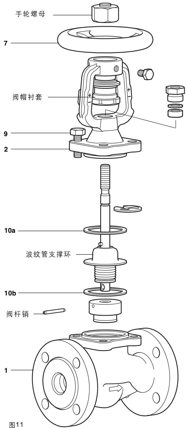
Parts shown with solid lines in the diagram are available as spare parts. Parts shown with dashed lines are not supplied.
Available spare parts
| Valve body/bonnet gaskets and stem seal | 10a, 10b, 8 (2 pieces) |
|---|---|
| Stem and bellows assembly (please specify model: BSA or BSAT) | 6, 5 |
| Disc (and optional disc) - please provide a detailed description | 4 |
Ordering spare parts
Order spare parts according to the descriptions in the spare parts table above, and specify the valve model and size.
Please note: For customer convenience, spare parts are supplied as kits to ensure that all parts required for maintenance are included. For example, when ordering a stem/bellows assembly, parts (10a and 10b), (8) and (6, 5) are also included.
Example: 1 - Spirax Sarco bellows-sealed stop valve BSA-DN15. PN16 valve body/bonnet gaskets and stem seal.
Note: The gaskets contain sharp-edged metal supports. Take care when handling them.