1. Safety information
Safe operation of the product can be guaranteed only when it is properly installed, commissioned, used and maintained by qualified personnel in accordance with these Installation and Maintenance Instructions. The general installation safety requirements for pipeline and plant construction, as well as the requirements for the correct use of tools and safety equipment, must also be observed.
1.1 Intended use
Before installation, verify that the product is suitable for the intended use and application conditions by referring to these Installation and Maintenance Instructions, the name-plate and the Technical Information Sheet.
BT6-B and BT6-B Food+ comply with the requirements of the European Pressure Equipment Directive 2014/68/EU and fall within SEP category. Products in this category are not CE marked as required by the Directive.
- This product is specifically designed for steam, air or water/condensate, which are Group 2 fluids under the Pressure Equipment Directive. If the product is intended for any other fluid, contact Spirax Sarco to confirm its suitability.
- Check material suitability, pressure and temperature, as well as the maximum and minimum operating values. If the product’s maximum operating limits are lower than the system limits, or if product failure could result in dangerous overpressure or overtemperature, install a safety device in the system.
- Determine the correct installation position and fluid flow direction.
- Spirax Sarco products are not designed to withstand external stresses generated by the connected system. The installer is responsible for assessing these stresses and taking appropriate measures to minimise their effects.
- Before installation in steam or other high-temperature applications, remove all connection protection covers and the protective film from the name-plate.
- BT6-B Food+ is suitable for systems that can operate an EC1935-compliant process. To reduce the risk of unintended additives in the system, the end user must perform an appropriate CIP cleaning cycle before first use in food-contact applications. The list of materials that may come into direct or indirect contact with food is provided in the product’s Declaration of Conformity.
1.2 Access, lighting and the surrounding area
Ensure safe access before operating the product. Where necessary, provide a protected working platform. If lifting is required, arrange suitable lifting equipment. Ensure adequate lighting at locations requiring detailed or complex work.
Also consider the current or historical contents of the pipeline, including flammable materials, substances hazardous to health and extreme temperatures. Areas around the product may contain explosion hazards, oxygen-deficient atmospheres such as tanks or pits, hazardous gases, extreme temperatures, hot surfaces, welding fire hazards, excessive noise or moving machinery.
1.3 The system, pressure and temperature
Before carrying out any work, consider the effect on the entire system. Operations such as closing isolation valves and switching off electrical isolation must not put other parts of the system or personnel at risk. Open and close isolation valves slowly to prevent system shock.
Confirm that pressure has been isolated and safely vented to atmospheric pressure. Consider double isolation, with two valves isolated and the intervening space vented, and lock or tag closed valves. Do not assume that the system is fully depressurised even when the pressure gauge indicates zero.
After isolation, allow sufficient time for the temperature to return to normal to avoid burns. If Viton components approach or exceed 315 °C (599 °F), they may decompose and form hydrofluoric acid. Avoid skin contact and inhalation of fumes. If PTFE components approach or exceed 260 °C (500 °F), they will release toxic fumes. Smoking must be prohibited in areas where PTFE is stored, handled or processed.
1.4 Tools, protective equipment, work permits and handling
Before starting work, prepare suitable tools and consumables, and use only genuine Spirax Sarco spare parts. Assess whether protective clothing is required to protect against chemicals, high or low temperatures, radiation, noise, falling objects, and eye or face hazards.
All work must be carried out or supervised by suitably competent personnel. Installation and operating personnel must be trained in the correct use of this product. Where a site operates a work permit system, the requirements of that system must be followed. Warning signs should be displayed where necessary.
Manual handling of large or heavy products may cause injury, particularly back injuries. Assess the risks associated with the task, personnel, load and working environment, and use an appropriate handling method.
1.5 Residual hazards, freezing, disposal and returns
During normal use, the external surface of the product may become very hot. Under maximum permitted operating conditions, the temperature of some product surfaces may exceed 177 °C (350 °F). Many products cannot drain completely by themselves. Take particular care when removing or dismantling them from an installation.
In environments where temperatures may fall below freezing, protect systems that cannot self-drain against frost damage. This product is recyclable and, when disposed of properly, generally presents no ecological hazard. Take care of the risk of high-temperature decomposition when disposing of Viton and PTFE components. Do not incinerate them. When returning products, provide information on the risks associated with contamination residues or mechanical damage in accordance with health, safety and environmental regulations, and include the relevant safety data sheets.
2. Product Information
2.1 Product Description
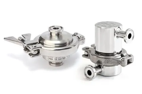
Spirax Sarco BT6-B sanitary balanced-pressure thermostatic steam trap is designed to discharge condensate from clean (chemical-free) and pure steam applications while minimising condensate retention. Typical applications include sterile steam barriers, isolation and vent installations, main steam line drainage, and CIP/SIP applications for vessels, reactors and process pipelines.
BT6-B is manufactured from 316L material. Its crevice-free body design, combined with a 15° inclined seat, ensures complete drainage. The standard temperature-sensing element is highly sensitive to changes in condensate temperature. Under typical operating conditions, when the pressure is below 2.4 bar g at a point 50 mm above the trap, the nominal opening point is 2 °C below the saturated steam temperature. Actual performance may be affected by operating pressure, installation and environmental conditions.
Each steam trap is individually packaged in an ISO CLASS 7 clean environment, fitted with protective end caps and sealed in a protective plastic bag.
BT6-B Food+ is suitable for steam and condensate applications and complies with the EC1935:2004 requirements for food contact materials, as well as the EC2023:2006 requirements for good manufacturing practice for food contact materials and articles.
Options
- High-capacity model.
- Model for main steam line drainage applications.
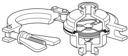
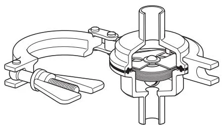
- Tube-ended or sanitary clamp-ended connections.
Standards
The standard BT6-B and BT6-B Food+ comply with ASME BPE and the European Pressure Equipment Directive 2014/68/EU. All seals comply with:
- FDA CFR Title 21, Paragraph 177.1550.
- USP Class VI Biological Reactivity Cytotoxicity Testing In-Vitro <87> and In-Vivo <88>, extracted for 1 hour at 121 °C.
- Animal-Derived Ingredient Free (ADI Free).
BT6-B Food+ also complies with:
- EC1935:2004 for food contact materials.
- EC2023:2006 for good manufacturing practice for food contact materials and articles.
2.2 Surface Finish and Certificates
The standard internal surface finish is below 0.6 μm Ra (25 micro-inch Ra), and the external surface finish is below 1.0 μm Ra (40 micro-inch Ra).
The following options are available when ordering:
- Electropolishing.
- Grease-free finish.
- Weld-end caps.
Available certificates include:
- EN 10204 3.1 material certificate.
- Typical internal surface finish certificate.
- FDA and USP Class VI test declaration and ADI Free certificate of conformity.
- TSE-BSE declaration.
- EC1935:2004 declaration of conformity (Food+ series only).
- BS EN ISO 14644-1:2015 Class 7 cleanroom declaration of conformity.
- Passivation certificate.
- Typical test report.
All certificate and inspection requirements must be specified when ordering and may incur additional charges depending on the certificate type. For further product data, refer to technical information TI-P180-30.
2.3 Sizes and Piping Connections
Sanitary clamp-ended connections:
| Standard | Version | Type | Size | ||||||
| ASME BPE | Type A | 1/2" | 3/4" | ||||||
| Type B | 1" | 1 1/2" | |||||||
| ISO1127 | 1997 | Series 1 | DN25 | DN40 | |||||
| ISO1127 | 1997 | Variations | DN15 | DN20 | |||||
| DIN32676 | 2001-02 | Series 2 | DN15 | DN20 | DN25 | DN40 | |||
| DIN32676 | 2009-05 | Series A | DN15 | DN20 | DN25 | DN40 | |||
| DIN32676 | 2009-05 | Series B | DN8 | DN10 | DN15 | DN20 | DN25 | DN32 | DN40 |
| DIN32676 | 2009-05 | Series C | 1/2" | 3/4" | 1" | 1 1/2" | |||
Tube-ended connections:
| Standard | Version | Type | Size | ||||||
| DIN11866 | 2016-11 | Series A | DN15 | DN20 | DN25 | DN40 | |||
| DIN11850 | 1999-01 | Series-2 | DN15 | DN20 | DN25 | DN40 | |||
| ISO1127 | 1997 | Series 1 | DN15 | DN20 | DN25 | DN40 | |||
Note: Available types should be checked against the SSP list. For other connection types, consult Spirax Sarco. ASME BPE connections are available for BT6-B Food+.
2.4 Pressure and Temperature Limits
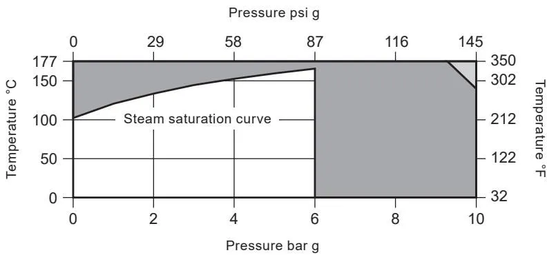
The product must not be used in the prohibited areas shown in the chart. Use should also be avoided in areas where internal components could be damaged. For sanitary clamp-ended connections, the maximum pressure or temperature may be limited by the gasket or sanitary clamp used. Consult Spirax Sarco for detailed information.
| Body design conditions | PN10 | ||
| PMA | Maximum allowable pressure | 10 bar g @ 140 °C | 145 psi g @ 284 °F |
| TMA | Maximum allowable temperature | 177 °C @ 9.2 bar g | 350 °F @ 133 psi g |
| Minimum allowable temperature | -10 °C | -14 °F | |
| PMO | Maximum operating pressure for saturated steam service | 6 bar g | 87 psi g |
| TMO | Maximum operating temperature | 165 °C @ 6 bar g | 329 °F @ 87 psi g |
| Minimum operating temperature | 0 °C | 32 °F | |
| The product can be safely used under full vacuum conditions | |||
| Maximum cold hydraulic test pressure | 15 bar g | 218 psi g | |
3. Installation
Before installation, read and comply with the safety information in Section 1. Confirm that the product is suitable for the intended installation conditions by referring to the installation and maintenance instructions, name-plate and technical information sheet.
- Check the materials, pressure and temperature, including their maximum values. If the product’s maximum operating limits are lower than the system limits, install a safety device in the system to prevent overpressure.
- Determine the correct installation position and fluid flow direction.
- Before installation in steam or other high-temperature applications, remove all connection protective caps and the name-plate protective film.
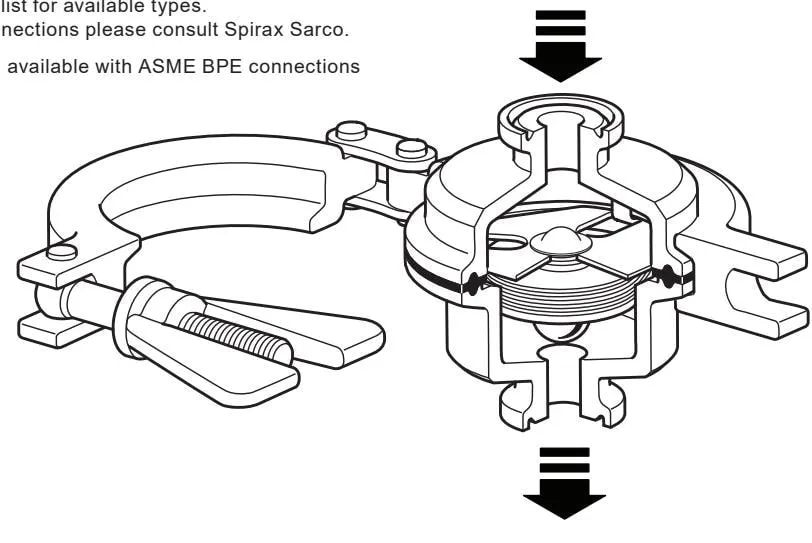
- The trap is designed for vertical downward-flowing pipelines to provide self-drainage. Check the flow direction arrow during installation. Fittings, clamps and gaskets required for tube-ended connections are not supplied with the product.
- Do not expose the temperature-sensing element to superheated conditions, as excessive expansion may cause damage. The installation should include a suitable cooling section to prevent condensate from flowing back into the process equipment under normal operating conditions.
Note: Do not overtighten the clamp. Overtightening may cause the seal to expand or extrude and interfere with the temperature-sensing element support. Normally, it is only necessary to eliminate looseness and then tighten the nut by no more than a further half turn.
If the trap is to undergo a hydraulic pressure test (maximum pressure 15 bar g), the internal components must be removed and the standard gasket replaced with a Viton gasket. After replacing the gasket or removing the internal components, the clamp must be retightened to 50 lbf.in (5.65 Nm).
Handle the body and temperature-sensing element carefully to avoid damaging machined surfaces. If the trap discharges to atmosphere, confirm that the discharge location is safe, as the discharge fluid temperature may reach 100 °C (212 °F).
4. Commissioning
After installation or maintenance, confirm that the system is fully functional and test all alarms or protective devices. As with all steam systems, raise the pressure slowly to avoid damaging sensitive equipment.
5. Operating Principle
BT6-B operates using a stainless-steel bellows filled with a WFI temperature-sensing liquid. When cold or during start-up, the bellows is fully open, allowing large quantities of air, condensate and/or CIP fluid to be discharged. As the system approaches steam temperature, the liquid inside the bellows expands and the valve closes the trap to prevent live steam loss. The closing point is very close to steam temperature, ensuring effective drainage of the system.
6. Spare Parts and Maintenance
Read and follow the safety information in Section 1 before carrying out maintenance.
6.1 Spare Parts
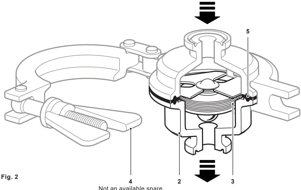
Available spare parts are shown with solid lines; components shown with grey lines are not available as spare parts.
| Liquid-filled temperature-sensing element assembly | 3 and 5 | |
| These items are available as spare parts. | Gasket | 5 |
| Other components are not available as spare parts. | Valve body (outlet), including valve seat | 2 |
When ordering spare parts, use the descriptions in the “Available spare parts” column and specify the trap size and type.
Example: 1 liquid-filled temperature-sensing element assembly for a 1/2” BT6-BH sanitary balanced-pressure thermostatic steam trap.
6.2 Maintenance Procedure
Before carrying out maintenance, isolate the trap from the steam supply and condensate return lines, and allow the pressure to return slowly to atmospheric pressure. The trap assembly should then be allowed to cool.
Note: Removing the body clamp before the trap has cooled to 60 °C or below may damage the liquid-filled temperature-sensing element assembly.
Handle the valve body and temperature-sensing element carefully to avoid damaging the machined surfaces. During maintenance, remove the sanitary clamps from the pipe connections and take the complete trap off the pipeline. After removing the body sanitary clamp (4), the trap inlet and outlet valve body (including valve seat) (2), gasket (5), and liquid-filled temperature-sensing element assembly (3) can be removed for cleaning or replacement.
When reassembling, use a new gasket and ensure that the valve head is positioned to close the valve seat orifice. Refit and tighten the sanitary clamp before returning the trap to service. Check for leaks and retighten as necessary.
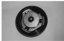
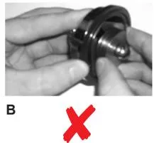
The gasket may sometimes be difficult to remove from the metal components, and the temperature-sensing element mounting plate may stick to the gasket. To avoid damage, do not separate the temperature-sensing element by prying or pulling on the welded capsule. Instead, gently lift the gasket from the valve body as shown below.
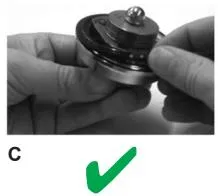
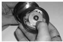
After cleaning or replacement, reassemble using a new gasket and position the valve head so that it can close the valve seat orifice. Refit and tighten the sanitary clamp before returning the trap to service. Check for leaks and retighten as necessary.