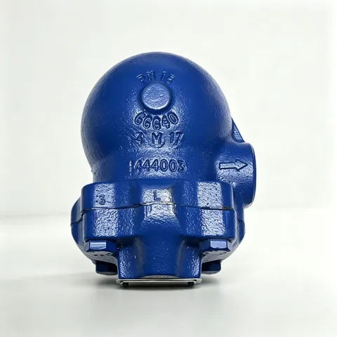

Description
The CA10S is a ball float automatic drain trap for air and gas systems. The cast iron body and stainless steel valve mechanism make it suitable for high-temperature applications or applications involving corrosive condensate.
Sizes and Pipe Connections
3/4” screwed BSP (BS 21 parallel thread) or NPT.
A 1/2” connection is provided for a balance pipe.
Optional Extras
Drain cock connection: The cover can be drilled and tapped 3/8” BSP or NPT for fitting a drain cock.
Limiting Conditions
| Parameter | Value |
|---|---|
| Body design conditions | PN16 |
| PMA - Maximum allowable pressure | 16 bar g |
| TMA - Maximum allowable temperature | 220°C |
| TMO - Maximum operating temperature | 220°C |
| ΔPMX - Maximum differential pressure | 14 bar |
| Cold hydraulic test pressure | 24 bar g |
Operating Range
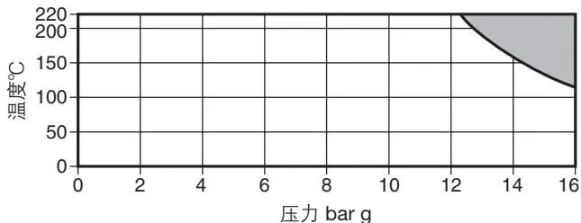

The product must not be used in this region.
ΔPMX maximum differential pressure
| Specific gravity | 1.0 | 0.9 | 0.8 | 0.7 | 0.6 |
|---|---|---|---|---|---|
| ΔPMX bar | 14.0 | 13.8 | 11.7 | 8.6 | 5.0 |
Materials
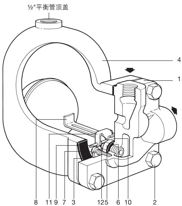
| No. | Part | Material | Material standard |
|---|---|---|---|
| 1 | Body | Cast iron | DIN 1691 GG 20 |
| 2 | Cover bolts | Steel | BS 3692 Gr. 8.8 |
| 3 | Cover gasket | Reinforced exfoliated graphite | |
| 4 | Cover | Cast iron | DIN 1691 GG 20 |
| 5 | Valve seat | Stainless steel | BS 970 431 S29 |
| 6 | Valve seat gasket | Stainless steel | BS 1449 304 S11 |
| 7 | Pivot frame assembly screws | Stainless steel | BS 6102 Gr. A2 Class 50 |
| 8 | Float and lever | Stainless steel | BS 1449 304 S16 |
| 9 | Pin | Stainless steel | B 970 431 529 |
| 10 | Support frame | Stainless steel | BS 1449 304 S16 |
| 11 | Pivot frame | Stainless steel | BS 1449 304 S16 |
| 12 | Valve cone+ | Stainless steel |
+The CA10S valve cone is permanently attached to the float and lever.
Certification
The body and cover are available with EN 10204 2.2 material certification.
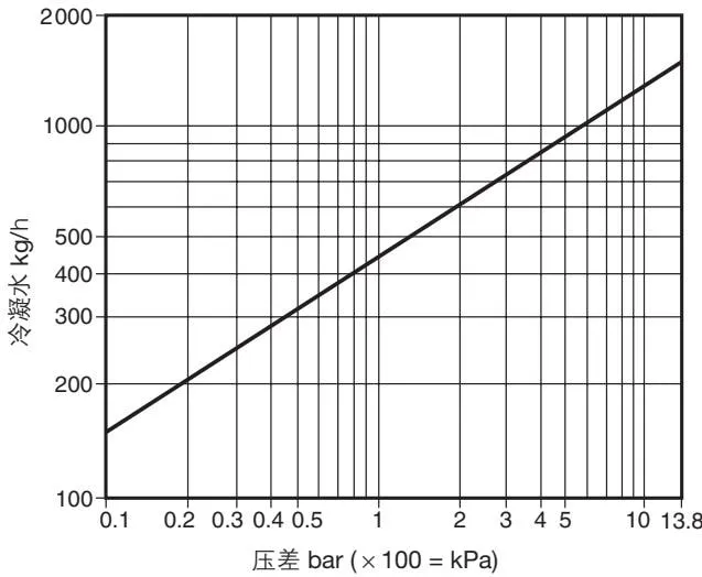
Capacity
Safety
Pressure
Before maintaining the trap, consider whether fluid may remain in the pipeline. Ensure that the upstream and downstream lines are isolated and vented to atmospheric pressure. This can be achieved by fitting a DV depressurization valve. Do not assume that the system is depressurized even when the pressure gauge indicates zero.
Temperature
Allow sufficient time for the unit to cool after isolation to avoid the risk of burns. Consider whether protective clothing, including safety glasses, is required.
Installation
The trap must be installed with the inlet at the top to ensure that the float mechanism moves vertically. A 1/2” connection is provided at the top of the cover for a balance pipe to ensure optimum operation. Connect the balance pipe upward from the high-level connection to the space being drained.
Maintenance
How to Fit the Main Valve Assembly
Close the upstream and downstream isolation valves, loosen the cover bolts, and remove the existing mechanism. Apply a small amount of jointing compound to the main valve thread and gasket, then fit the main valve to the body. Attach the support frame and pivot frame to the body using the assembly screws, but do not tighten them.
Connect the float arm to the pivot frame using the pin. Move the complete assembly to align the main valve with the valve seat bore. Hold the assembly in position and tighten the screws to the recommended torque. Move the float up and down several times to check for correct operation, and ensure that the valve cone is correctly aligned with the valve seat. Tighten the cover bolts evenly to the recommended torque. Slowly open the isolation valves.
Disposal
This product is recyclable and will not cause ecological problems if disposed of correctly.
Ordering Information
Example: 1 - 3/4” BSP CA10S trap with cast iron body and cover.
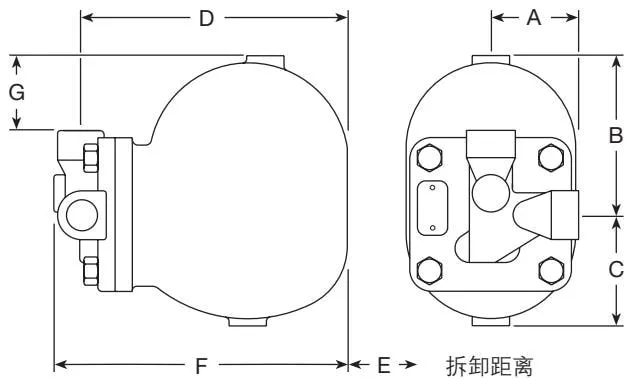
Dimensions/Weights (Approximate) mm and kg
| Size | A | B | C | D | E | F | G | Weight |
|---|---|---|---|---|---|---|---|---|
| 3/4” | 60 | 111 | 77 | 195 | 165 | 217 | 50 | 6.8 |
Spare Parts
Available spare parts are shown in solid lines. Parts shown in dashed lines are not available.
Available spare parts
| Spare part | Part numbers |
|---|---|
| Main valve assembly with float | 5,6,7,8+12,14,15,16 |
| Gasket set (3 sets) | 3,6 |
Ordering Spare Parts
Use the description given in the available spare parts list above and state the trap size and model. Example: 1 - main valve assembly for a 3/4” CA10S.