
1. Safety Information
Read the safety information guide supplied with the product and comply with relevant national or local regulations.
This product can only operate safely when it is correctly installed, commissioned, and maintained by qualified personnel in accordance with the operating instructions.
During installation, the installation and safety guidelines for piping and plant facilities must be followed, suitable tools must be used, and necessary safety equipment must be provided.
The product is designed and constructed to withstand the forces encountered in normal use. Misuse of the product, or incorrect installation that does not follow the installation and maintenance instructions, may damage the product, invalidate the CE marking, and cause personal injury.
This product contains PTFE material, which can release toxic fumes at excessive temperatures.
2. Product Information
2.1 Introduction
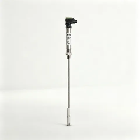
Sensors are available in a range of standard probe lengths and can be cut to the required length before installation. The CP30 sensor has a 3/8 in BSP taper thread connection (1/2 in NPT for the UL version) and can be installed on a Spirax Sarco sensor elbow, a threaded flange, or directly at a boiler connection.
The CP30 sensor can be used with BC3100, BC3200 or BC3210 controllers and includes a sensor cleaning function (UK Patent 2276943). This function loosens, makes porous, or dislodges scale on the probe, enabling the sensor to continue detecting at its initial calibration value.
Warning: This function is not a substitute for a suitable boiler water treatment system. If scale forms on the sensor probe, scale will also form inside the boiler; a qualified water treatment specialist must be consulted to avoid potential hazards.
The sensor is certified by Underwriters Laboratories (UL) for use with BC3100, BC3200 and BC3210 blowdown controllers. These controllers provide a low-voltage supply to the sensor, with UL electrical ratings of 20 Vdc and 14 Vac at 10 mA.
2.2 Application
The Spirax Sarco CP30 conductivity sensor is used with a controller to measure the conductivity (or TDS) of water, typically for blowdown monitoring and control of steam boilers. Each product is supplied with a DIN 43650 cable plug with a Pg11 cable gland; UL version sensors are additionally supplied with a 1/2 in NPT conduit thread adaptor and four flying leads.
2.3 Probe Lengths mm (inches)
Standard probe lengths: 300 mm (11.8 in), 500 mm (19.7 in), 1 000 mm (39.4 in) and 1 500 mm (59.0 in).
2.4 Limitations
| Item | Parameter |
|---|---|
| Maximum boiler pressure | 32 bar g (464 psi g) |
| Maximum temperature | 239°C (462°F) |
| Maximum ambient temperature | 70°C (158°F) |
| Minimum distance from boiler firetube to sensor | 20 mm (3/4 in) |
| Minimum insertion depth (vertically mounted sensor) | 100 mm (4 in) |
| Maximum cable length (sensor to controller) | 100 m (330 ft) |
| Minimum conductivity | 10 μS/cm or 10 ppm |
| Protection rating (cable plug) | IP65 |
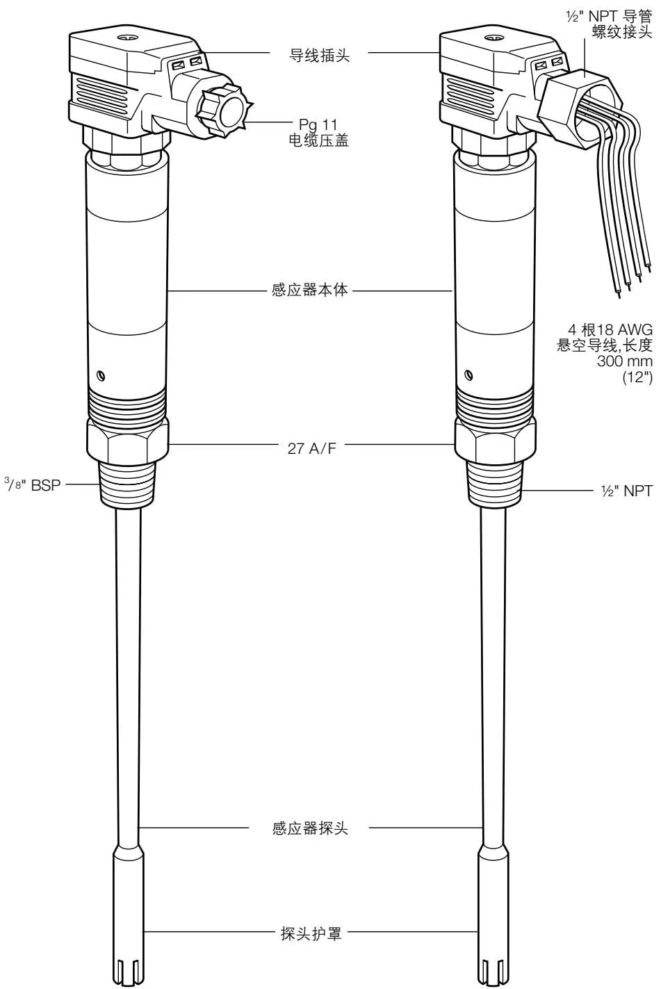
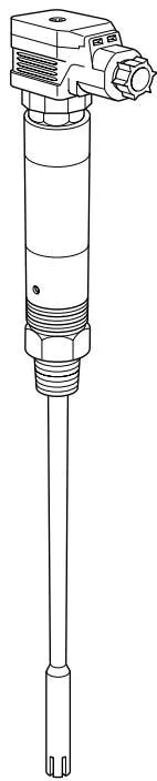
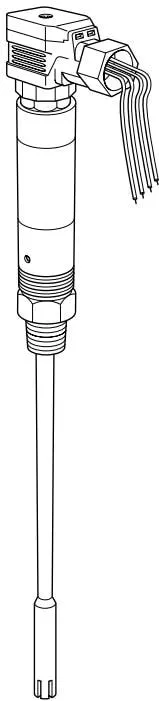
Figure 1 CP30 sensor standard version Figure 2 CP30 sensor UL version
3. Installation
Warning: When installing the sensor outdoors, weatherproof protection must be fitted.
Warning: The boiler must be depressurized and drained before installation. Where possible, consult the boiler manufacturer to determine the optimum sensor installation position and TDS range.
Note:
- Always remove the label from the probe shroud before installation.
Sensors with probe lengths up to 500 mm (20 in) may be installed horizontally or vertically; sensors with longer probes must be installed vertically. The sensor should be installed in a position where it can detect boiler water conductivity and as far away as possible from the boiler feedwater inlet. A minimum clearance of 20 mm (3/4 in) must be maintained between the sensor tip and the boiler firetube; when installed vertically, the probe must be immersed in water to a depth of at least 100 mm (4 in).
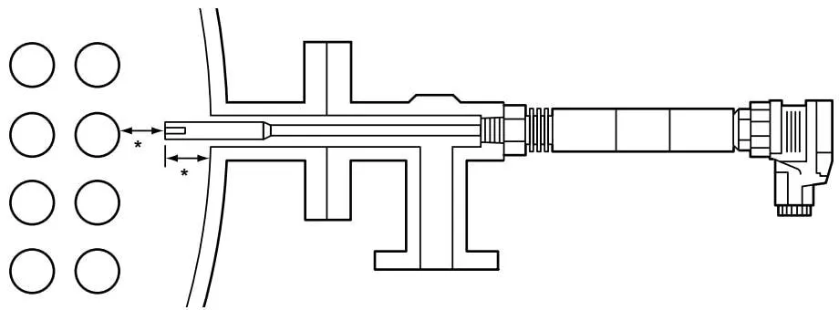
* 20 mm (3/4 in) minimum
Figure 3 Typical installation diagram, sensor fitted on a sensor elbow (3/8 in BSP only)
3.1 Cutting the Sensor Probe to the Required Length
Warning:
The PTFE probe shroud is secured to the sensor probe by an internal spring and can only rotate freely in one direction (clockwise or counterclockwise, depending on the spring installation direction). Forcing the shroud to rotate, or removing it while rotated, will damage the product.
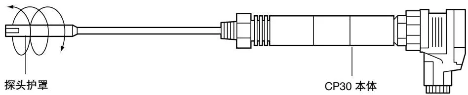
Figure 4 Removing the probe shroud
Rotate the probe shroud while pulling it off the sensing probe (see Figure 4).
Note:
- The shroud can only be rotated in one direction.
- Do not attempt to remove the spring from the sensor shroud.
Step 1
Cut the sensor to the required length and chamfer the end.

Figure 5
Step 2
Remove a 50 mm (2 in) length of PTFE protective sleeve from the end of the sensor (Figure 6).

Figure 6
Step 3
Screw the sensor into the probe shroud and spring (Figure 7).
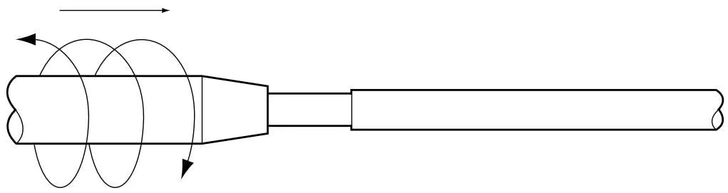
Figure 7
Step 4
Check that the end of the sensor probe is flush with the probe shroud. A certain amount of free clearance is normal.
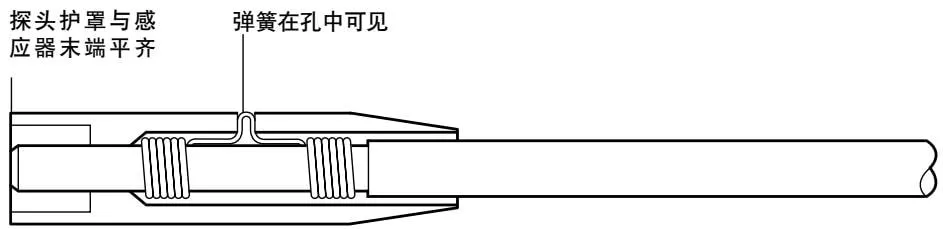
Figure 8
3.2 Installation Procedure
- Check that the internal and external threads are in good condition.
- Apply a maximum of three turns (no more) of PTFE thread sealing tape to the sensor threads.
Warning: Do not use excessive sealing tape or paste-type sealants.
- Install and tighten the sensor by hand first, then tighten with a suitable wrench. Never use a pipe wrench.
- Due to the nature of taper/parallel thread connections, a specific tightening torque is not recommended.
- Do not overtighten; threads should always remain visible on the sensor.
Note: The sensor threads should not be tightened “all the way” (i.e. until the hexagon nut on the sensor body contacts the female threaded connection surface), unless the threads are significantly worn or the female thread is outside permissible tolerance; in this case, the flange/connection should be replaced or remachined.
3.3 Removal
Warning: Before loosening or removing the sensor, ensure that the boiler or vessel has been depressurized and drained to atmospheric pressure.
- Use a correctly sized wrench; never use a pipe wrench.
- Check the internal and external threads for signs of damage. Overtightening may damage the threads, causing wear or localized cold welding (galling/burrs).
- If damage is found, replace the sensor.
- Ensure that drain/vent holes are clear and not covered.
4. Wiring Diagram
* Complete wiring information is given in the controller’s installation and maintenance guide.
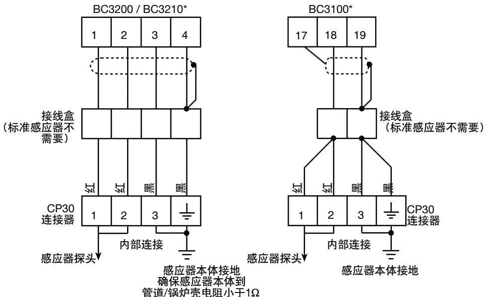
Figure 9
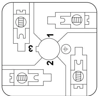
Figure 10 Connector view with wire plug removed
4.1 Wiring
Cable installation must comply with BS-6739 Process control instrumentation systems: installation design and implementation, or the local equivalent. For installations in the United States and Canada, wiring must comply with the National Electrical Code (NEC) or the Canadian Electrical Code (CEC).
The wire cover contains an 8-way terminal block to facilitate wiring. Use 2-core or 4-core high-temperature shielded cable with a cross-sectional area of 1 mm² and a maximum length of 100 m (330 ft). Pirelli FP 200 or Delta Crompton Firetuf OHLS cable is suitable for standard CP30 sensors; for UL model sensors, Class 1 shielded cable rated at not less than 75°C (167°F) must be used to connect the terminal box and controller.
Allow sufficient cable length to permit removal of the wire plug and to ensure that no deforming force is applied to the sensor.
Remove the central screw to withdraw the wire plug.
Note: To protect the sensor, a gasket must be fitted between the wire plug and the sensor connector. When reconnecting the wire plug, ensure that the gasket is in place and that all contact surfaces are clean and undamaged.
Remove the central screw and open the hinged outer cover to access the connector module inside the wire plug.
The connector module on the standard CP30 conductivity sensor can be rotated by 90° to facilitate wiring:
- Remove the fixing screw and hinged outer cover, and withdraw the plug;
- Remove the connector module and reposition it as required.
The connector module on UL model sensors cannot be rotated.
4.2 Additional Wiring Information for UL Model Sensors
The plug is fitted with four color-coded flying leads, 18 AWG and 300 mm (12 in) long, which can be cut as required and connected to a suitable metal terminal box. A suitable length of flexible metal conduit must be installed between the sensor and the terminal box to provide environmental protection and electrical connection; the wire plug is therefore fitted with a 1/2 in NPT threaded conduit fitting.
Warning: The sensor flying leads are rated at 221°F (105°C) and this temperature must not be exceeded in use.
The flexible conduit and terminal box for the leads must not be shared with other control wiring, otherwise product performance may be impaired or reduced.
Unlike the standard CP30, the wire plug on UL models cannot be rotated by 90°, otherwise the internal wiring will be damaged.
Ensure that any condensate that may form in the conduit does not accumulate in the sensor wire connector or terminal box.
5. Maintenance
The sensor does not require frequent maintenance.
If the sensor probe becomes scaled, the boiler will also have scaled internally; immediate boiler water treatment is recommended. Some Spirax Sarco controllers offer a sensor adjustment option (UK Patent No. 2276943) to minimize the effects of scaling, but this is not a substitute for proper boiler water treatment.
- Remove the sensor once a year and take off the probe shroud (see Section 3.1).
- Clean the sensor probe with a high-quality emery cloth.
- Clean the PTFE probe shroud and probe sleeve with a cloth or bristle brush.
- Before refitting, ensure that the probe shroud is flush with the end of the sensor probe.
6. Troubleshooting
Most installation problems are caused by incorrect wiring. A thorough check of all wiring is recommended, including, where necessary, the connections to the controller.
The condition of an installed sensor can be assessed by measuring its AC resistance using a Spirax Sarco MS1 conductivity meter and extension leads (see separate literature).
When carrying out a continuity check, measure from the sensor probe to terminals 1 and 2, and from the sensor body to terminal 3 and the earth point.
7. Spare Parts
A spare probe shroud and spring assembly is available, part number 4031580.
To fit the probe shroud, proceed as follows:
- Clean and chamfer the end of the sensor.
- Insert the sensor into the probe shroud/spring assembly while rotating the shroud until the end of the sensor is flush with the shroud.
- The probe shroud/spring assembly can only rotate freely in one direction.
A certain amount of free play is normal.
Related Products
See the CP30 conductivity sensor for a product introduction, technical specifications, and associated documentation.