
1. Safety Information
Correct installation, commissioning, and maintenance by competent, qualified personnel in accordance with the operating instructions are the only guarantee of safe operation of this product (see Section 1.1). During installation, the installation and safety guidelines for pipework and plant facilities must be observed, suitable tools must be used, and the necessary safety equipment must be provided.
Do not install the sensor outdoors unless a protective device is fitted.
Drain/vent holes must be kept clear and must not be covered.
1.1 Preparation Before Use
Before installation, refer to the installation and maintenance guide, nameplate, and technical data to confirm that this product is suitable for the application. This product complies with the European Pressure Equipment Directive and falls under the SEP (Sound Engineering Practice) category; as required by the Directive, such products do not carry the CE marking.
i) This product is designed for steam, compressed air, and inert industrial gases, all of which are Group 2 fluids under the Pressure Equipment Directive. If it is intended for use with other fluids, contact Spirax Sarco first to confirm the suitability of this product for that application. ii) Check material suitability and the maximum/minimum pressure and temperature values. If the maximum allowable values of the product are lower than the system requirements, or if a product failure could cause overpressure or overtemperature, safety devices must be fitted in the system to prevent the limits from being exceeded. iii) Determine the correct installation location and fluid flow direction. iv) Spirax Sarco products cannot withstand external stresses imposed by the installation system. The installing party is responsible for assessing these stresses and taking adequate measures to minimize them. v) For steam or other high-temperature applications, remove all protective caps from connections and protective film from nameplates before installation.
1.2 Access
Ensure safe access to the equipment. Before work, provide a safe working platform; if necessary, arrange suitable lifting equipment.
1.3 Lighting
Ensure adequate lighting, especially when performing complex operations.
1.4 Hazardous Liquids or Gases in Pipework
Consider the media that may be present in the pipework and their condition, including flammable substances, substances hazardous to health, and substances at extreme temperatures.
1.5 Hazardous Environment Around the Product
Be aware of explosion hazards, oxygen-deficient atmospheres (e.g., tanks, pits), extreme temperatures, hot surfaces, fire hazards (e.g., welding), excessive noise, and moving machinery.
1.6 System
Before work, consider the effect on the overall system: could any operation (e.g., closing an isolation valve, electrical isolation) place other parts of the system or personnel at risk? Hazards may arise from vents or protective devices being isolated, or from control or alarm failure. Isolation valves should be opened/closed slowly to avoid system oscillations.
1.7 Pressure Systems
Ensure the system has been isolated from all pressure sources and safely vented to atmosphere. Consider double isolation (two shutoffs and venting); closed valves should be locked or tagged. A pressure gauge reading zero is not proof that the system is fully depressurized.
1.8 Temperature
After isolation, allow the equipment to cool sufficiently to ambient temperature to avoid burns.
1.9 Tools and Spare Parts
Before starting work, ensure suitable tools and consumable parts are available. Use only genuine Spirax Sarco spare parts.
1.10 Protective Clothing
Assess whether protective clothing is required to prevent injury from, for example, chemicals, high/low temperatures, noise, falling objects, and conditions that may injure the eyes and face.
1.11 Permits to Work
All work must be carried out or supervised by qualified personnel. Installation and maintenance personnel should be trained to perform the correct procedures in accordance with these instructions. A formal permit-to-work system should be operated; where no such system exists, the responsible person should be aware of the work and, where necessary, assign someone responsible for safety. Post safety warnings where necessary.
1.12 Handling
Manual handling of Spirax Sarco products carries a risk of injury. Lifting, pushing, pulling, carrying, or supporting loads with the body can cause injury, particularly to the back. A risk assessment of the task, individual, load, and working environment is recommended, together with correct handling methods.
1.13 Residual Heat
In normal use, the external surfaces of the product may be very hot. At the maximum allowable working temperature, the surface temperature of some products can reach 350°C (662°F). Many products are not self-draining; take particular care when removing or dismantling products from pipework (see Maintenance Guide).
1.14 Freezing
For products that are not self-draining, freeze protection must be provided if the ambient temperature may fall below freezing.
1.15 Disposal
This product is recyclable and, if disposed of properly, will not harm the environment. The following exceptions apply:
- PTFE must be disposed of only by approved methods; incineration is prohibited;
- PTFE should be kept in a separate container, not mixed with other waste, and consigned to a waste disposal site.
1.16 Returned Products
When users and distributors return products to Spirax Sarco, they must comply with UK and EU health, safety, and environmental regulations. For contaminated residues or mechanical damage that could endanger health, safety, or the environment, information on the relevant hazards and precautions must be provided, including material data for all substances identified as relevant to health and safety.
2. Product Information
2.1 Application
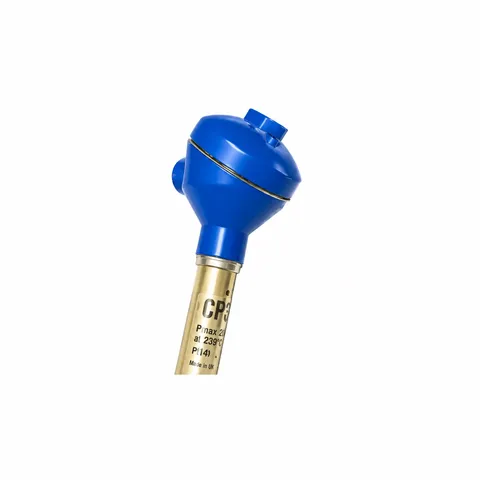
The Spirax Sarco CP32 conductivity sensor is used with a controller to measure water conductivity (related to TDS), typically for blowdown monitoring and control of steam boilers.
2.2 Introduction
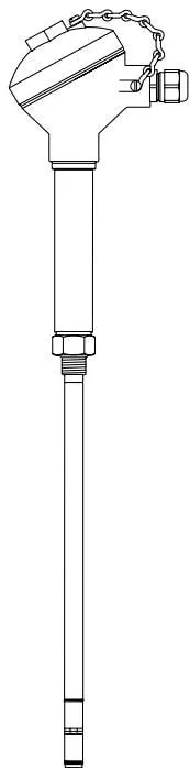
The CP32 is available in three standard probe lengths, with 3/8 in BSP threads (1/2 in NPT must be specified separately), and can be mounted in a Spirax Sarco sensor elbow, a threaded flange, or directly at the boiler connection.
The CP32 has an integral temperature sensor. When used with a BC3200 or BC3210 controller, it can detect scale formation (UK Patent No. 2297843) and automatically perform a probe cleaning cycle (UK Patent No. 2276943).
This cleaning cycle causes scale on the sensor to become loose, porous, or to flake off, so that the sensor continues to provide conductivity measurements at its original calibration. Warning: This function is not a substitute for water treatment. If scale appears on the sensor, scale will also be present inside the boiler, and water treatment must be improved to avoid hazards.
2.3 Available Lengths, mm (in)
Standard probe lengths: 300 mm (11.8 in), 500 mm (19.7 in), and 1 000 mm (39.4 in).
Note: The 1 000 mm sensor can only be installed vertically.
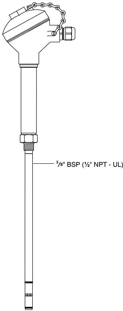
Figure 1
2.4 Limitations
| Item | Parameter |
|---|---|
| Maximum boiler pressure | 32 bar g (464 psi g) |
| Maximum temperature | 239°C (462°F) |
| Maximum ambient temperature | 55°C (131°F) |
2.5 Technical Data
| Item | Parameter |
|---|---|
| Protection rating (terminal/cable gland) | IP65 |
| Minimum distance from boiler firetube to sensor | 10 mm (3/8 in) |
| Minimum insertion depth (vertically mounted sensor) | 100 mm (4 in) |
| Maximum cable length (sensor to controller) | 100 m (330 ft) |
| Minimum conductivity | 10 μS/cm or 10 ppm |
3. Installation
The CP32 sensor is available in three standard probe lengths: 300, 500, or 1 000 mm (11.8, 19.7, and 39.4 in). The probe must not be cut.
The 300 mm and 500 mm models can be installed vertically or horizontally; the 1 000 mm model can only be installed vertically.
Warning: Before installation, the boiler must be depressurized and drained. Where possible, consult the boiler manufacturer to determine the best sensor installation location and TDS range.
3.1 Installation Location
- Install the sensor in a location where it can detect boiler water conductivity.
- Keep it as far as possible from the boiler feedwater inlet.
- Keep it as close as possible to the boiler centerline to reduce the risk of the sensor being in the upper steam bubble area or the lower high-concentration suspended solids area of the boiler.
Note: The probe must be at least 10 mm (3/8 in) from the boiler tube wall and inserted at least 55 mm (2 1/8 in) into the boiler. Allowance should be made during installation to obtain good measurement results. For vertical installation, the sensor must be immersed to a depth of at least 100 mm (4 in).
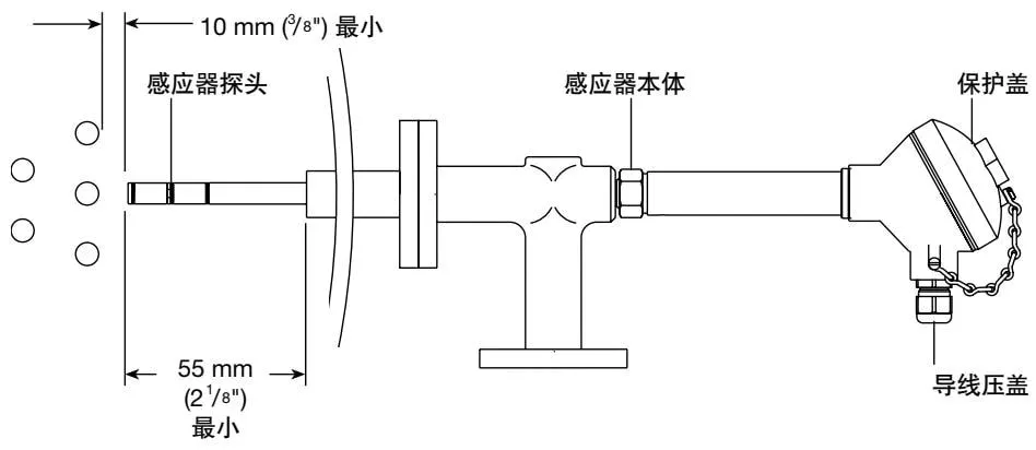
Figure 2 Installation Diagram
3.2 Installation Procedure
- Check that the internal and external threads are in good condition.
- Apply a maximum of three turns (no more) of PTFE thread sealing tape to the sensor threads.
Warning: Do not use excessive sealing tape or paste-type sealants.
- Install and tighten the sensor by hand first, then tighten with a suitable wrench.
- Due to the nature of tapered/parallel threaded connections, a specified tightening torque is not recommended.
- Do not overtighten; threads should always remain visible on the sensor.
Note: The sensor threads should not be bottomed out (i.e., the hex nut on the sensor body contacting the surface of the female threaded connection), unless the threads are clearly excessively worn or the female threads are outside the permitted tolerance, in which case the flange/connection should be replaced or re-machined.
3.3 Removal
Warning: Before loosening or removing the sensor, ensure the boiler or vessel has been depressurized and drained to atmospheric pressure.
- Use a correctly sized wrench.
- Check the internal and external threads for signs of damage. Overtightening can damage threads, causing wear or localized cold welding (galling/burrs).
- If damage is found, replace the sensor.
- Check the sensor insulation for tears or damage.
4. Wiring Diagram
Cable installation must comply with BS-6739, Process Control Instrumentation Systems: Installation Design and Implementation, or the local equivalent. For installations in the United States and Canada, wiring must comply with the National Electrical Code (NEC) or the Canadian Electrical Code (CEC).
The 8-way terminal inside the wiring cover facilitates wiring. Use a high-temperature shielded cable with 7 cores and a cross-sectional area of 1 mm² (18-16 AWG), with a maximum length from sensor to controller of 100 m (330 ft). Pirelli FP 200 or Delta Crompton Firetuf OHLS cable is suitable for the standard CP32 sensor; for installations in the United States and Canada, use a Class 1 shielded cable rated at not less than 75°C (167°F). Connect the wires and shield as shown in the diagram below.
Warning: Do not connect any wiring to the smaller (five-way) terminal box. This terminal box can only accommodate the five sensor wires; additional wiring can easily cause damage.
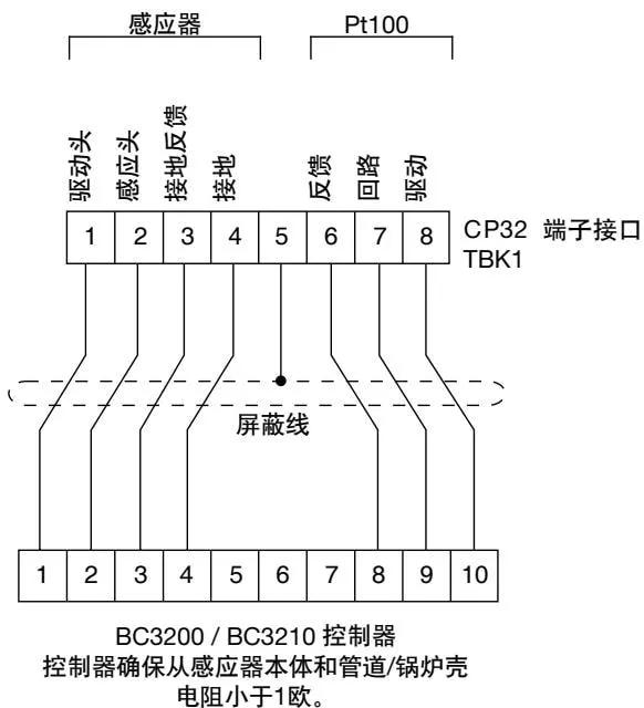
Figure 3 Wiring Diagram
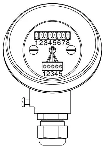
Wiring Arrangement Diagram
5. Maintenance
The sensor requires no routine maintenance, but annual removal, inspection, and cleaning are recommended. In addition, if the controller continuously indicates a fault for more than 12 hours, the sensor should be removed for inspection and cleaning.
If the sensor begins to scale, the automatic control system will descale it and restore conductivity sensing. However, this system is not a substitute for proper water treatment; under extremely severe conditions, the sensor may still require additional cleaning.
Manual Sensor Cleaning
Caution: The sensor has no serviceable parts; dismantling the sensor will cause permanent damage.
Remove the sensor, clean the probe with a damp cloth, and remove hard scale with high-grade wet/dry abrasive paper (maximum 600 grit). Do not sand the insulation. If the probe is severely corroded, replace the sensor.
Use PTFE sealing tape when reinstalling; do not use paste-type sealants (see Section 3).
6. Spare Parts
Only the following spare parts are available:
- Sealing O-ring;
- Eight-way plug-in terminal block.
Ordering Spare Parts
Order by the spare part names above and specify the product model.
Example: 1 sealing O-ring for Spirax Sarco CP32 sensor.
7. Troubleshooting
Problems encountered during commissioning are usually caused by wiring errors or incorrect settings. Therefore, a thorough check is recommended first.
Checking the sensor using the cell constant
The BC3200 / BC3210 controllers can check the drive head condition without removing the sensor: the sensor condition is determined by calculating the cell constant.
When operating normally and with little scaling, the drive head cell constant should be between 0.2 and 0.6 (see the Troubleshooting section in the BC3200 / BC3210 controller Installation and Maintenance Guide). This method is not suitable for checking the sensing head.
Checking the sensor using the MS1
The installed sensor can be checked using a Spirax Sarco MS1 conductivity meter and extension leads (see the CP32 internal wiring diagram).
Drive head
- Connect the MS1 extension leads between terminals 1 and 3.
- Calculate the drive head cell constant from the reading as described in the MS1 manual.
A reading between 0.2 and 0.6 indicates that the sensor is operating correctly; a higher value indicates scaling on the sensor.
Sensing head
- As in the drive head check, connect the MS1 between terminals 2 and 3.
The sensing head cell constant is normal between 0.2 and 0.6; values up to 0.8 are also acceptable.
Pt100 resistance check
- The power supply must be isolated before testing.
- Measure the resistance between terminals 7 and 8 on TBK1 (a standard ohmmeter may be used). The resistance should be between 100 and 168 Ω. If it is not, check the internal wiring against the wiring diagram.
- Terminal 3 should be grounded to the sensor body.
Related Products
See the CP32 dual-probe conductivity sensor for product overview, technical specifications, and supporting documentation.