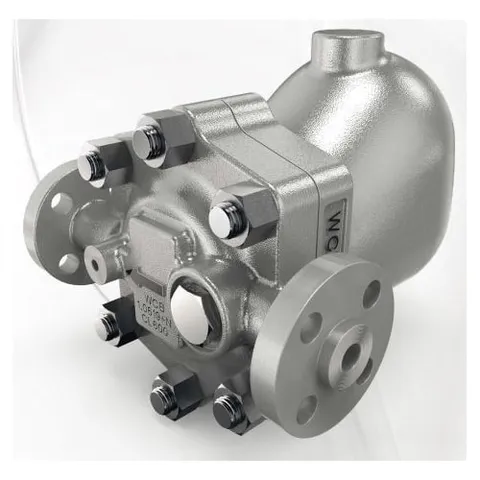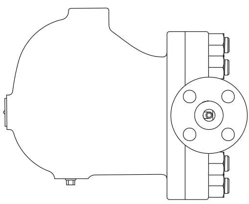
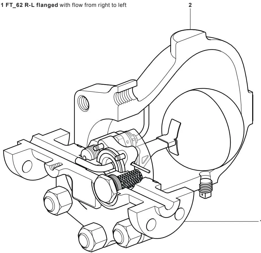
The illustration shows the flanged FT_62 series.
1. Safety information
Safe operation of this product can only be guaranteed if it is properly installed, commissioned, used and maintained by qualified personnel in accordance with these installation and maintenance instructions (see Section 1.11). The general installation and safety requirements for pipework and plant construction, together with the requirements for the correct use of tools and safety equipment, must also be complied with.
1.1 Intended use
Refer to these installation and maintenance instructions, the product nameplate and the technical information sheet to confirm that the product is suitable for the intended use or application. FTC62 and FTS62 comply with the requirements of the Pressure Equipment Directive (PED).
It should be noted that, as required by the Directive, products of this type must bear this mark.
| Product | Group 2 gases | Group 2 liquids | |
| FTC62 and FTS62 | DN15, DN20 and DN25 | 2 | SEP |
i) These products have been specifically designed for use with steam, air or condensate/water, which are within Group 2 of the Pressure Equipment Directive (PED) referred to above. The products can also be used with other fluids, but if this is contemplated, Spirax Sarco should be contacted to confirm the suitability of the product for the proposed application.
ii) Check the suitability of the materials, and the maximum and minimum pressure and temperature values. If the maximum operating limits of the product are lower than those of the system in which it is being installed, or if product malfunction could result in a dangerous overpressure or overtemperature, ensure that a safety device is included in the system to prevent these limits from being exceeded.
iii) Determine the correct installation location and the direction of fluid flow.
iv) Spirax Sarco products are not designed to withstand external stresses that may be induced by any system to which they are connected. It is the responsibility of the installer to consider these stresses and take adequate precautions to minimise them.
v) Before installation in a steam or other high-temperature application, remove all protective covers from the connections and, where applicable, the protective film from all nameplates.
1.2 Access
Ensure safe access before working on the product and, if necessary, provide a safe working platform with suitable protection. Arrange suitable lifting equipment if required.
1.3 Lighting
Ensure that adequate lighting is provided, particularly where detailed or complex work is required.
1.4 Hazardous liquids or gases in the pipeline
Consider what is currently in the pipeline or what may have been in the pipeline previously. Consider: flammable materials, substances hazardous to health and extreme temperatures.
1.5 Hazardous environment around the product
Consider: areas at risk of explosion, oxygen-deficient environments (for example, tanks and pits), hazardous gases, extreme temperatures, hot surfaces, fire hazards (for example, during welding), excessive noise and moving machinery.
1.6 The system
Consider the effect of the proposed work on the complete system. Could any proposed action (for example, closing isolation valves or switching off electrical isolation) put any other part of the system or personnel at risk? Hazards may include isolation of vents or protective devices, or the disabling of controls or alarms. Isolation valves should be opened and closed slowly to avoid system shocks.
1.7 Pressure systems
Ensure that all pressure is isolated and safely vented to atmospheric pressure. Consider double isolation (double block and bleed) and lock or tag closed valves. Do not assume that the system has depressurised completely just because the pressure gauge reads zero.
1.8 Temperature
Allow sufficient time for the temperature to return to normal after isolation to avoid the risk of burns.
1.9 Tools and consumables
Before starting work, ensure that suitable tools and/or consumables are available. Use only genuine Spirax Sarco replacement parts.
1.10 Protective clothing
Consider whether you and others in the vicinity require protective clothing to protect against hazards from chemicals, high and low temperatures, radiation, noise, falling objects, and risks to the eyes and face.
1.11 Work permits
All work must be carried out or supervised by a suitably competent person. Installation and operating personnel should be trained in the correct use of the product according to these installation and maintenance instructions.
Where a formal “work permit” system is in force, it must be complied with. Where no such system exists, it is recommended that a responsible person knows what work is being carried out and, where necessary, arranges for an assistant whose primary responsibility is safety.
Display “warning notices” where necessary.
1.12 Handling
Manual handling of large and/or heavy products may present a risk of injury. Lifting, pushing, pulling, carrying or supporting loads by bodily force can cause injury, particularly to the back. It is recommended that the risk be assessed according to the task, the individual, the load and the working environment, and that appropriate handling methods be adopted accordingly.
1.13 Residual hazards
The product’s external surfaces may become very hot during normal operation. At the maximum permitted operating conditions, the surface temperature may exceed 425 °C (797 °F). Many products are not self-draining. Take particular care when dismantling or removing the product from an installation (refer to the maintenance instructions).
1.14 Freezing
For products that are not self-draining, precautions must be taken to protect them against frost damage if they may be exposed to temperatures below freezing point.
1.15 Disposal
Unless otherwise stated in these installation and maintenance instructions, this product is recyclable. No ecological hazard is anticipated provided that appropriate care is taken during disposal.
1.16 Returning products
Customers and stockists are reminded that, under European health, safety and environmental laws, when returning products to Spirax Sarco they must provide information about any hazards and the precautions required due to health, safety or environmental risks that may result from contamination residues or mechanical damage. This information must be provided in writing, including health and safety data sheets relating to any substances identified as hazardous or potentially hazardous.
1.17 Safe working with cast iron products in steam systems
Cast iron products are commonly used in steam and condensate systems. They are completely safe when correctly installed in accordance with good steam engineering practice. However, because of its mechanical properties, cast iron has less tolerance than other materials such as ductile iron or carbon steel. The following good engineering practices are required to prevent waterhammer and ensure safe working conditions in steam systems.
Safe handling
Cast iron is a brittle material. If the product is dropped during installation and there is a risk of damage, the product must not be used unless it has been fully inspected and pressure tested by the manufacturer.
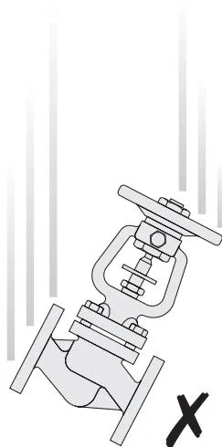
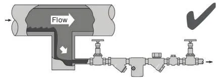
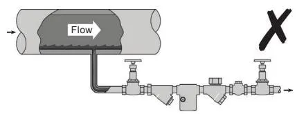
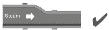
Preventing waterhammer - condensate drainage from steam mains
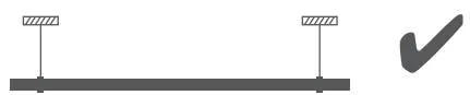
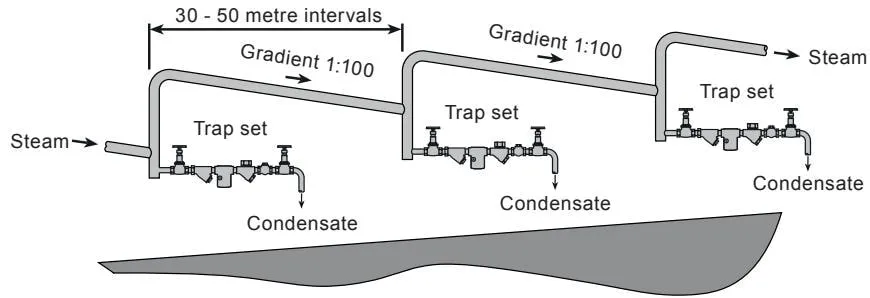
Steam mains - do’s and don’ts
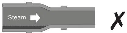
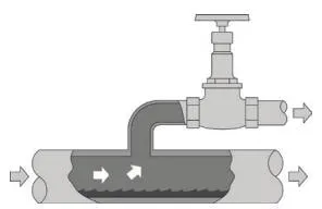

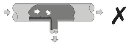
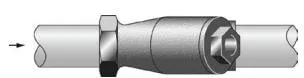

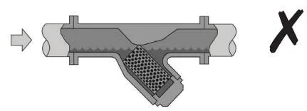
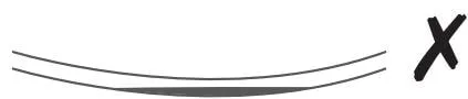

When installing the product or reassembling it after maintenance:
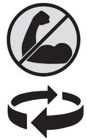
Do not overtighten. Use the correct torque values.
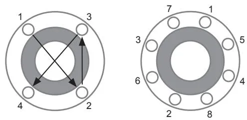
Flange bolts should be tightened gradually and evenly in a diagonal sequence to ensure uniform loading and alignment.
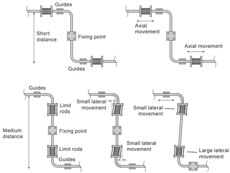
Thermal expansion:
2. Product information
2.1 Overview
The FT_62 series float steam traps feature an integral automatic air vent.
FT_62 series:
| Available models | Model | Body and cover | Optional accessories |
| FTC62 | Carbon steel body, stainless steel internals | On request, the cover (2) can be drilled and tapped for the installation of a balance pipe. This option is available only when specified at the time of order. | |
| FTS62 | Stainless steel body, stainless steel internals | ||
| Flow direction options when facing the body | L-R | Flow direction from left to right | |
| R-L | Flow direction from right to left | ||
Standards
These products fully comply with the requirements of the Pressure Equipment Directive (PED) and carry the relevant mark.
Certificates
Certificates complying with EN 10204 3.1 are available for these products.
Note: All certificate and inspection requirements must be specified at the time of order.
Note: For further product information, refer to the following technical information sheets:
FTC62 TI-P179-13
and
FTS62 TI-P179-14
2.2 Sizes and pipe connections
| 1/2", 3/4" and 1" | BSP or NPT threads |
| 1/2", 3/4" and 1" | Socket-weld ends to BS 3799 and Class 3000 lbs |
| Standard flanges: | |
| DN15, DN20 and DN25 | EN 1092-1 PN100 flanges. Note: For PN100 models, the material used for the welded flanges of the FTC62 is carbon steel 1.0460, while that of the FTS62 is stainless steel 1.4301. For all models, the stud and nut materials are: studs = ASTM A193 B7, nuts = ASTM A194 Gr. 4 (in accordance with EN 10269) |
| 1/2", 3/4" and 1" | ASME B 16.5 Class 600 flanges |
2.3 Pressure/temperature limits (ISO 6552)
| FTC62 | Threaded | |
| Socket-weld | See section 2.4, page 9 | |
| ASME Class 600 flanges | ||
| EN 1092 PN100 flanges | See section 2.5, page 10 | |
| FTS62 | Threaded | |
| Socket-weld | See section 2.6, page 11 | |
| ASME Class 600 flanges | ||
| EN 1092 PN100 flanges | See section 2.7, page 12 | |
2.4 FTC62 pressure/temperature limits (ISO 6552)
Threaded, socket-weld and ASME Class 600 flanges
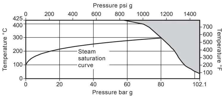
The product must not be used in the shaded or prohibited areas shown in the diagram, nor must the PMA or TMA parameters for the relevant end connection be exceeded.
| Body design conditions | ASME Class 600 | ||
| PMA | Maximum allowable pressure | 102.1 bar g @ 38 °C | 1480 psi g @ 100 °F |
| TMA | Maximum allowable temperature | 425 °C @ 57.5 bar g | 797 °F @ 834 psi g |
| Minimum allowable temperature | -29 °C | -20 °F | |
| PMO | Maximum operating pressure under saturated steam conditions | 80 bar g @ 296 °C | 1160 psi g @ 565 °F |
| TMO | Maximum operating temperature | 425 °C @ 57.5 bar g | 797 °F @ 834 psi g |
| Minimum operating temperature. Note: For lower operating temperatures, consult Spirax Sarco. | 0 °C | 32 °F | |
| Minimum operating differential pressure | 0.1 bar g | 1.45 psi g | |
| ΔPMX | Maximum differential pressure | FTC62-46 | 46 bar |
| FTC62-62 | 62 bar | ||
| Maximum designed cold hydraulic test pressure: | 153.2 bar g | 2222 psi g | |
2.5 FTC62 pressure/temperature limits (ISO 6552)
EN 1092 PN100 flanges
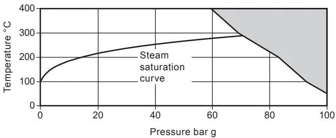
The product must not be used in the shaded or prohibited areas shown in the diagram, nor must the PMA or TMA parameters for the relevant end connection be exceeded.
| Body design conditions | PN100 | ||
| PMA | Maximum allowable pressure | 100 bar g @ 50 °C | |
| TMA | Maximum allowable temperature | 400 °C @ 59.5 bar g | |
| Minimum allowable temperature | -10 °C | ||
| PMO | Maximum operating pressure under saturated steam conditions | 70.8 bar g @ 287 °C | |
| TMO | Maximum operating temperature | 400 °C @ 59.5 bar g | |
| Minimum operating temperature. Note: For lower operating temperatures, consult Spirax Sarco. | 0 °C | ||
| Minimum operating differential pressure | 0.1 bar g | ||
| ΔPMX | Maximum differential pressure | FTC62-46 | 46 bar |
| FTC62-62 | 62 bar | ||
| Maximum designed cold hydraulic test pressure: | 150 bar g | ||
2.6 FTS62 pressure/temperature limits (ISO 6552)
Threaded, socket-weld and ASME Class 600 flanges
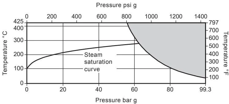
The product must not be used in the shaded or prohibited areas shown in the diagram, nor must the PMA or TMA parameters for the relevant end connection be exceeded.
| Body design conditions | ASME Class 600 | ||
| PMA | Maximum allowable pressure | 99.3 bar g @ 38 °C | 1440 psi g @ 100 °F |
| TMA | Maximum allowable temperature | 425 °C @ 56 bar g | 797 °F @ 812 psi g |
| Minimum allowable temperature | -29 °C | -20 °F | |
| PMO | Maximum operating pressure under saturated steam conditions | 63.1 bar g @ 280 °C | 915 psi g @ 536 °F |
| TMO | Maximum operating temperature | 425 °C @ 56 bar g | 797 °F @ 812 psi g |
| Minimum operating temperature. Note: For lower operating temperatures, consult Spirax Sarco. | 0 °C | 32 °F | |
| Minimum operating differential pressure | 0.1 bar g | 1.45 psi g | |
| ΔPMX | Maximum differential pressure | FTS62-46 | 46 bar |
| FTS62-62 | 62 bar | ||
| Maximum designed cold hydraulic test pressure: | 149 bar g | 2161 psi g | |
2.7 FTS62 pressure/temperature limits (ISO 6552)
EN 1092 PN100 flanges
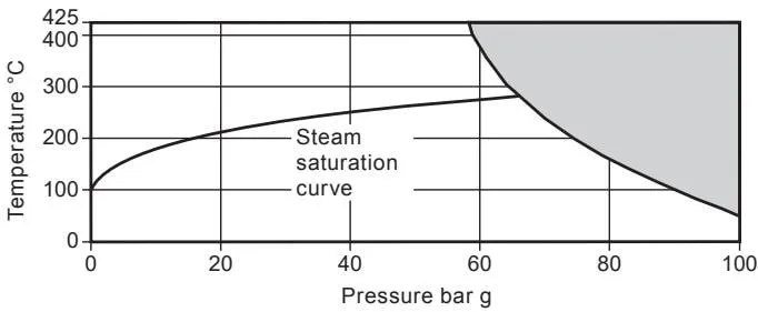
The product must not be used in the shaded or prohibited areas shown in the diagram, nor must the PMA or TMA parameters for the relevant end connection be exceeded.
| Body design conditions | PN100 | ||
| PMA | Maximum allowable pressure | 100 bar g @ 50 °C | |
| TMA | Maximum allowable temperature | 425 °C @ 58.9 bar g | |
| Minimum allowable temperature | -29 °C | ||
| PMO | Maximum operating pressure under saturated steam conditions | 65.8 bar g @ 283 °C | |
| TMO | Maximum operating temperature | 425 °C @ 58.9 bar g | |
| Minimum operating temperature. Note: For lower operating temperatures, consult Spirax Sarco. | 0 °C | ||
| Minimum operating differential pressure | 0.1 bar g | ||
| ΔPMX | Maximum differential pressure | FTS62-46 | 46 bar |
| FTS62-62 | 62 bar | ||
| Maximum designed cold hydraulic test pressure: | 150 bar g | ||
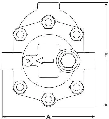
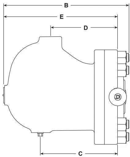
2.8 Flanged - dimensions/weights (approximate): mm and kg
Note: 1. Face-to-face dimensions for PN100 EN 1092-1 and ASME 600 B 16.5 flanges
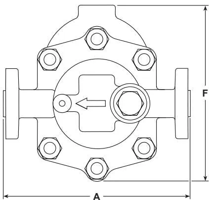
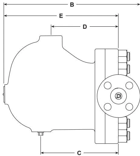
Figure 2
| Size | Flanges | Common dimensions | ||||||||
| PN100 | ASME 600 | |||||||||
| A | B | Weight | A | B | Weight | C | D | E | F | |
| DN15 | 300 | 304.0 | 25.0 | 261 | 299 | 24.0 | 172.5 | 148 | 251.5 | 239 |
| DN20 | 300 | 316.5 | 26.0 | 271 | 309 | 25.5 | 172.5 | 148 | 251.5 | 239 |
| DN25 | 300 | 321.5 | 28.0 | 291 | 314 | 27.0 | 172.5 | 148 | 251.5 | 239 |
2.9 Threaded and socket-weld - dimensions/weights (approximate): mm and kg
Note: 1. Face-to-face dimensions for PN100 EN 1092-1 and ASME 600 B 16.5 flanges
Figure 3
| Size | Threaded and socket-weld | Common dimensions | |||||
| A | B | Weight | C | D | E | F | |
| DN15 | 190 | 287.5 | 22.0 | 172.5 | 148 | 251.5 | 239 |
| DN20 | 190 | 287.5 | 22.0 | 172.5 | 148 | 251.5 | 239 |
| DN25 | 190 | 287.5 | 22.0 | 172.5 | 148 | 251.5 | 239 |
2.10 Capacities
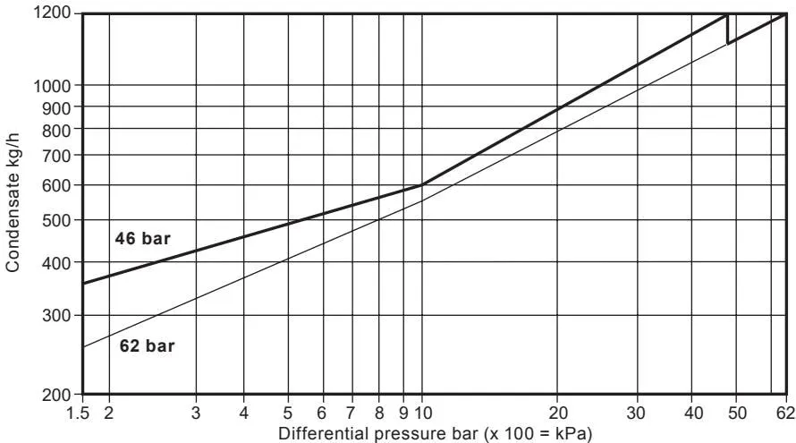
The capacities shown above are based on condensate at saturation temperature. When subcooled condensate is discharged, the air vent provides additional capacity. During start-up, when the condensate is cold, the integral bimetallic air vent opens and provides additional capacity through the main valve. The table below shows the minimum additional cold-water capacity provided by the air vent for all sizes.
Note: Air vent closing temperature range = 120 °C to 135 °C
For differential pressures below 1.5 bar g, the additional cold-water capacity is small.
| ΔP (bar) | 1.5 | 10 | 30 | 46 | 62 |
| FTC62 | Minimum additional cold-water capacity (kg/h) | ||||
| 46 bar models | 20 | 426 | 536 | 800 | |
| 62 bar models | 20 | 350 | 440 | 930 | 800 |
3. Installation
Note: Before carrying out any installation work, first read Section 1, “Safety information”.
Warning
Note 1: FT62 must be installed according to the flow direction indicated on the body. Ensure that the float arm is in a horizontal plane so that it can move vertically.
Note 2: It is recommended that a strainer be installed upstream of the steam trap. Follow good engineering practice and perform regular system maintenance to ensure that steam quality complies with industry standards.
Note 3: When installing the steam trap, the selected nuts, bolts and gaskets must comply with industry standards.
Nuts and bolts should be tightened to the torque specified by the applicable industry standards.
Fig. 4
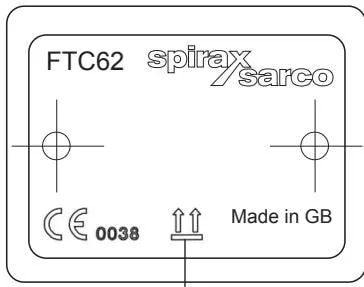
The nameplate indicates “This Way Up”.
Refer to these Installation and Maintenance Instructions, the product nameplate and the technical information sheet to confirm that the product is suitable for the intended installation conditions:
3.1 Check the materials and maximum pressure/temperature ratings. If the maximum operating limits of the product are lower than the operating limits of the system, ensure that safety devices are installed in the system to prevent overpressure.
3.2 Determine the correct installation position and fluid flow direction. Note that the flow direction is not the same for all FT_62 steam trap models or sizes. The flow direction is clearly marked on the body.
3.3 Before installation in steam or other high-temperature applications, remove all protective covers from the connections and, where applicable, remove any protective film from the nameplates.
3.4 The steam trap must be installed with the float arm in a horizontal plane so that it can move vertically. Note: The correct orientation of the steam trap can be visually checked by reading the text displayed on the body, cover and nameplate. When correctly installed, the text will be visible in the correct orientation.
3.5 The steam trap should be installed below the outlet of the steam system, with a short length of downpipe, typically 150 mm (6”), installed upstream of the trap. Without a downpipe, steam may pass over the condensate at the bottom of the pipe and reach the trap, particularly under low-load conditions.
3.6 If the steam trap is installed in an exposed location, it should be insulated or drained through a separate small thermostatic trap, such as Spirax Sarco No.8 or Bydrain.
3.7 Any steam trap discharging into a condensate return line subject to backpressure should have a check valve installed downstream. This is not normally caused by a rising condensate line. When the inlet pressure falls or the steam is shut off, the check valve prevents the steam space from becoming flooded with water.
3.8 Provide sufficient clearance to remove the cover from the body for maintenance. The maximum withdrawal distance for removing the cover is 250 mm (10”).
Note: If the steam trap discharges to atmosphere, ensure that the discharge is directed to a safe location. The discharge fluid temperature may reach 100 °C (212 °F).
4. Commissioning
After installation and maintenance, ensure that the system is fully functional. Test all alarm or protective devices.
After installation or maintenance, always open the isolation valve slowly to relieve system shock and check for leakage. Ensure that the system is fully functional and test all alarm or protective devices. The steam trap may be subjected to a cold hydraulic pressure test up to 1.5 times the PMA in accordance with Section 2, without removing any internal components. Pressures exceeding this limit may cause permanent damage to the float and result in steam trap failure.
5. Operation
The float steam trap is a continuous-discharge device that discharges condensate as soon as it forms. During start-up, the thermostatic air vent allows air to bypass the main valve, preventing air locking in the system. Hot condensate closes the air vent tightly, but once it enters the main chamber of the trap, the float rises and the connected lever mechanism opens the main valve, keeping the system free of condensate at all times. When steam reaches the trap, the float falls and closes the main valve. Float steam traps are known for their high start-up load-handling capacity, clean and tight shut-off, and resistance to waterhammer and vibration.
6. Spare Parts and Maintenance
Note: Before carrying out any maintenance procedure, read Section 1, “Safety information”.
Warning
The cover gasket contains a thin stainless steel support ring which may cause personal injury if handled or disposed of incorrectly.
Recommended tightening torques
| Item | Part | [inches or mm] | [Nm] | lbf ft | |
| 3 | 3/8" NPT square-head plug | 11 mm A/F | 3/8" NPT | As required | |
| 4 | 3/4" UNF hexagon nut | 1.125" A/F | 3/4" UNF | 252-260 | 186-192 |
| 6 | Strainer cap | 32 mm A/F | M28 x 1.5 | 170-190 | 125-140 |
| 9 | Air vent assembly | 32 mm A/F | M22 x 1.5 | 80-88 | 59-65 |
| 10 | Air vent pipe assembly | 11 mm A/F | M10 x 1.5 | 10-12 | 7-9 |
| 12 | M6 x 30 socket head cap screw | 5 mm A/F (hexagon key) | M6 | 14-16 | 10-12 |
6.1 Spare Parts
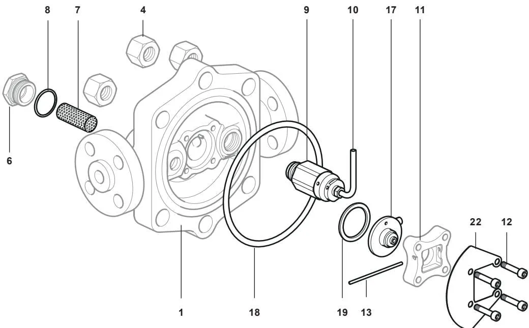
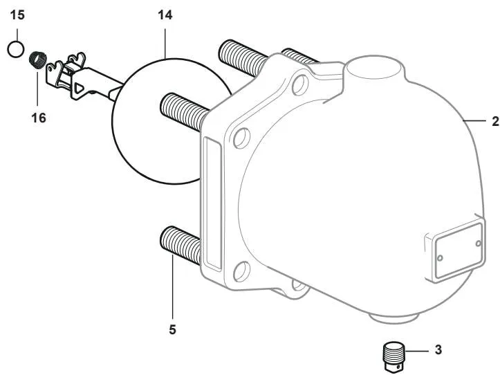
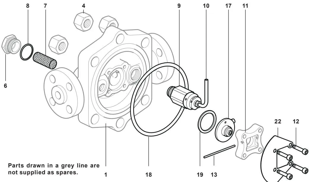
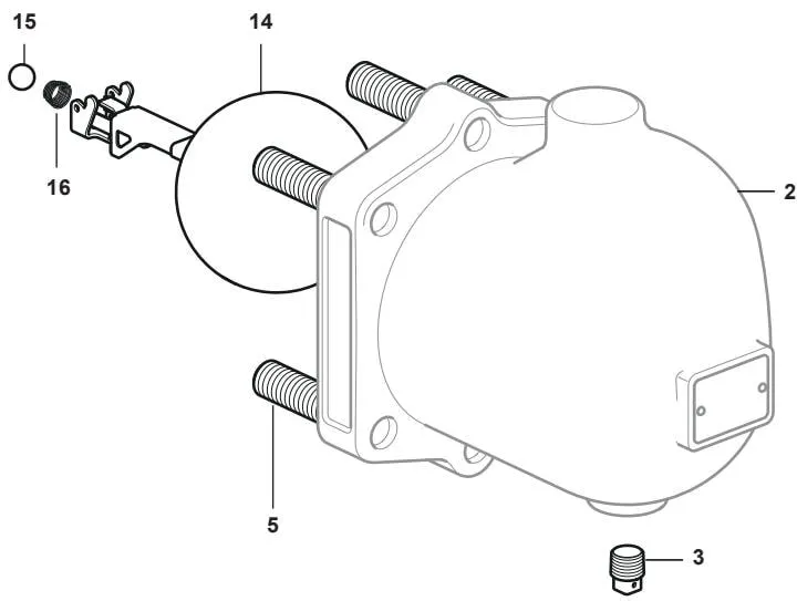
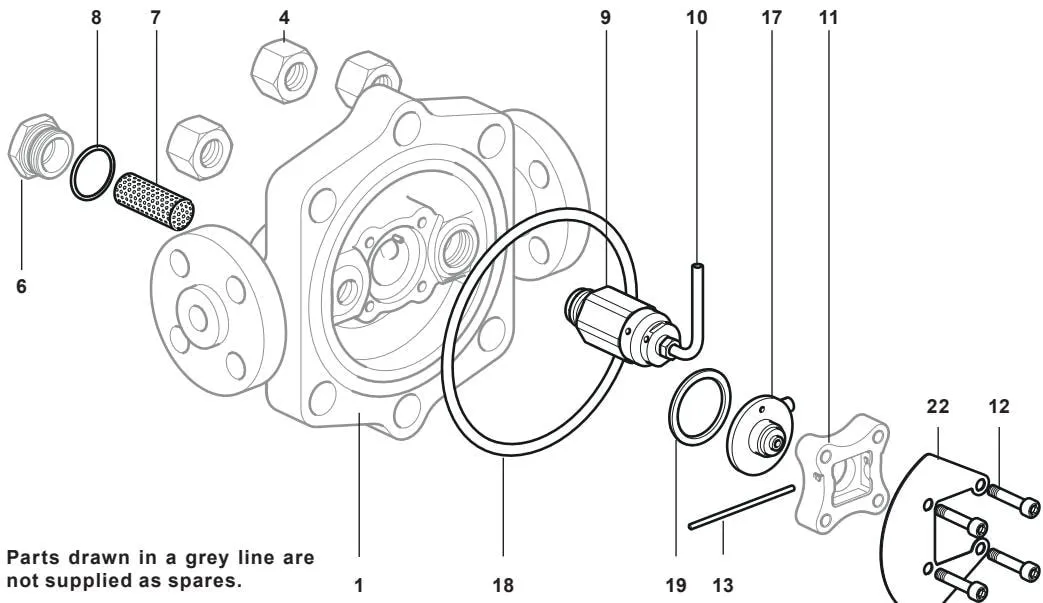
Available spare parts are shown with solid outlines. Components shown with grey lines are not supplied as spare parts.
Available Spare Parts
| Body/cover gasket set | ||
| Air vent assembly + air vent pipe | 9 and 10 | |
| Strainer screen + 'S' gasket | 7 and 8 | |
| Maintenance kit | 3/8" NPT taper plug | 3 |
| M6 x 30 long socket head cap screw (x 4) | 12 | |
| Pivot pin | 13 | |
| Float assembly | 14 | |
| 1/2" ∅ steel ball | 15 | |
| Taper spring | 16 | |
| Valve seat and discharge pipe assembly | 17 | |
| 'S' gasket + spiral-wound gasket | 8, 18 and 19 | |
| Baffle | 22 | |
| Overhaul kit | 3, 7, 8, 9, 10, 12, 13, 14, 15, 16, 17, 18, 19 and 22 | |
How to Order Spare Parts
When ordering spare parts, always use the description given in the “Available spare parts” column and specify the size and model of the steam trap, including the pressure range.
Example: 1 maintenance kit for a Spirax Sarco DN25 FTC62-62 float steam trap.
6.2 Maintenance
General safety information:
With suitable isolation in place, maintenance can be carried out with the trap in the pipeline.
- When reassembling, ensure that all mating surfaces are clean.
The trap can be serviced with the float in the pipeline or securely held in a vice.
Recommended tightening torques
| Item | Part | [inches or mm] | N m | lbf ft | |
| 3 | 3/8" NPT square-head plug | 11 mm A/F | 3/8" NPT | As required | |
| 4 | 3/4" UNF hexagon nut | 1.125" A/F | 3/4" UNF | 252-260 | 186-192 |
| 6 | Strainer cap | 32 mm A/F | M28 x 1.5 | 170-190 | 125-140 |
| 9 | Air vent assembly | 32 mm A/F | M22 x 1.5 | 80-88 | 59-65 |
| 10 | Air vent pipe assembly | 11 mm A/F | M10 x 1.5 | 10-12 | 7-9 |
| 12 | M6 x 30 socket head cap screw | 5 mm A/F (hexagon key) | M6 | 14-16 | 10-12 |
6.2.1 Main Valve Preassembly
- Hold the lever arm and float vertically, with the float facing downwards.
Place the taper spring (16) in the recess at the end of the lever arm, with the small end of the taper spring facing upwards, and place the steel ball (15) on top of the spring.
Insert the pin (13).
The pin holds the components in position until the preassembled unit is installed in the trap.
6.2.2 Valve Seat and Discharge Assembly
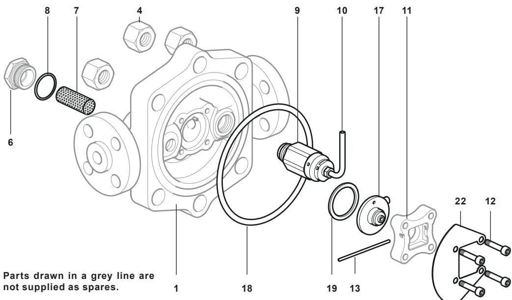
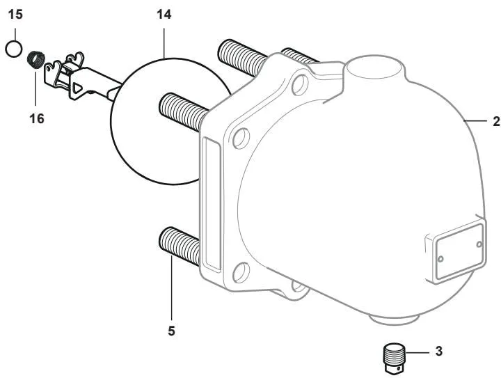
Unscrew the six 3/4” UNF (4) nuts securing the cover and remove the cover (2) to access the internal components.
Withdraw the pin (13) and remove the float assembly (14), stainless steel ball (15) and taper spring (16).
Unscrew the four M6 screws (12) and remove the seat retainer (11), thereby removing the valve seat and discharge pipe assembly (17) and baffle (22).
Replace the old parts with new ones and reassemble in the reverse order, tightening the screws (12), cover nuts and studs to the torques shown in the table. The tightening sequence for the 3/4” UNF (4) nuts and M6 (12) screws is given in Section 6.2.5.
Note: Ensure that the arrow on the seat retainer (11) points upwards.
6.2.3 Replacing the Air Vent Assembly
Unscrew the six 3/4” UNF (4) nuts securing the cover and remove the cover (2) to access the internal components.
- Then remove the air vent assembly (9) and air vent pipe (10).
Apply a small amount of anti-seize compound to the threads of the new air vent assembly (9) and its preassembled air vent pipe (10), and tighten to the torque specified in the table.
Note 1: The air vent pipe must be aligned with and point in the same direction as the directional arrow on the seat retainer (11).
Note 2: After the internal components have been assembled, the pin (13) may appear too long when fully inserted and contacting the air vent assembly. Do not cut it. It is intentionally long to prevent movement caused by vibration and therefore cannot become loose.
Recommended tightening torques
| Item | Part |  | inches or mm | N m | lbf ft | |
| 3 | 3/8" NPT square-head plug | 11 mm A/F | 3/8" NPT | As required | ||
| 4 | 3/4" UNF hexagon nut | 1.125" A/F | 3/4" UNF | 252-260 | 186-192 | |
| 6 | Strainer cap | 32 mm A/F | M28 x 1.5 | 170-190 | 125-140 | |
| 9 | Air vent assembly | 32 mm A/F | M22 x 1.5 | 80-88 | 59-65 | |
| 10 | Air vent pipe assembly | 11 mm A/F | M10 x 1.5 | 10-12 | 7-9 | |
| 12 | M6 x 30 socket head cap screw | 5 mm A/F (hexagon key) | M6 | 14-16 | 10-12 | |
6.2.4 How to Clean or Replace the Strainer Screen
Remove the strainer cap (6) to access the strainer screen.
Remove the strainer screen (7) and gasket (8).
Fit the new or cleaned strainer screen into the recess in the cap (6).
A new gasket (8) must always be fitted. Screw the cap (6) into the body and tighten to the recommended torque (170-190 Nm).
Note: A suitable anti-seize thread lubricant must be used.
6.2.5 General Notes
Apply a suitable anti-seize compound, such as FUCHS PCB or ROCOL J166, to the studs (5) and to both ends of the threads on components (6), (9) and (12), ensuring that the compound does not contact any sealing surface.
Apply anti-seize compound to the contact surfaces of the 3/4” UNF nuts (4) as well.
When fitting the 3/4” UNF nuts (4), the side marked with the heat number must face outwards.
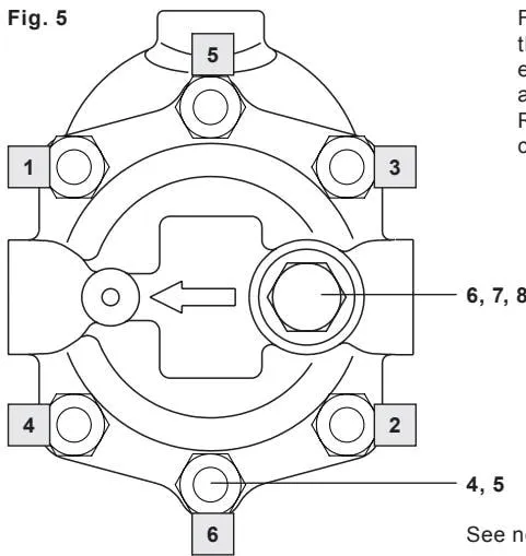
Tighten the 3/4” UNF nuts (4) in three stages: first to 60% of the final torque, then 80%, and finally to the value in the torque table. Follow the sequence shown in Figure 5 and repeat each stage at least twice to ensure even gasket loading.
Tighten the M6 cap screws (12) in three stages in the same way: first to 60% of the final torque, then 80%, and finally to the value in the torque table. Follow the sequence shown in Figure 6 on the facing page.
- Apply jointing sealant to the threads of item 3. Do not use PTFE tape.
Recommended tightening torques
| Item | Part | N m | lbf ft | ||
| inches or mm | |||||
| 3 | 3/8" NPT square-head plug | 11 mm A/F | 3/8" NPT | As required | |
| 4 | 3/4" UNF hexagon nut | 1.125" A/F | 3/4" UNF | 252-260 | 186-192 |
| 6 | Strainer cap | 32 mm A/F | M28 x 1.5 | 170-190 | 125-140 |
| 9 | Air vent assembly | 32 mm A/F | M22 x 1.5 | 80-88 | 59-65 |
| 10 | Air vent pipe assembly | 11 mm A/F | M10 x 1.5 | 10-12 | 7-9 |
| 12 | M6 x 30 socket head cap screw | 5 mm A/F (hexagon key) | M6 | 14-16 | 10-12 |
For the left-to-right option, rotate the body (1) through 180°. Regardless of the direction of flow, the open end of the air vent pipe assembly (10) must always point upwards.
Regardless of the direction of flow, the arrow on the seat retainer (11) must always point upwards.
See the notes on the torque tightening procedure.
See the notes on the torque tightening procedure.
Figure 6
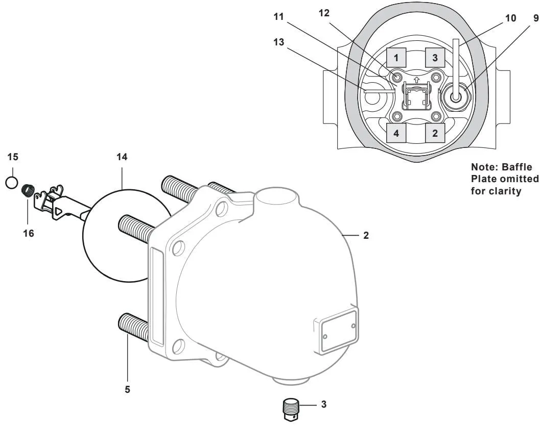
Note: The baffle has been omitted for clarity.