

- Safety Information
- Product Information
- Installation
- Commissioning
- Operation
- Maintenance
- Spare Parts
1. Safety Information
Safe operation of this product can only be guaranteed if it is properly installed, commissioned, and maintained by suitably qualified personnel in accordance with the operating instructions (see Section 1.11). Installation must comply with the installation and safety guidelines for pipework and plant construction, including the correct use of tools and the provision of necessary safety equipment.
1.1 Intended Use
Refer to the installation and maintenance instructions, nameplate, and technical documentation to ensure that the product is suitable for the intended application. This product complies with the requirements of the European Pressure Equipment Directive 97/23/EC. Marking is available if required. The Pressure Equipment Directive classification of the product is as follows:
| Product | Group 1 Gases | Group 2 Gases | Group 1 Liquids | Group 2 Liquids |
| SMC32 | - | SEP | - | SEP |
| SMC32F | - | SEP | - | SEP |
| SMC32Y | - | SEP | - | SEP |
| SMC32YF | - | SEP | - | SEP |
I) The product is designed for use with Pressure Equipment Directive Category 2 fluids, including steam, air, and water/condensate. For use with other fluids, consult Spirax Sarco.
II) Ensure that the product materials are suitable for the operating conditions and that the system maximum/minimum pressure and temperature are within the product design limits. If the product’s maximum operating limits are below the system operating conditions, or if product failure could result in overpressure or overtemperature, install a safety device to prevent hazardous conditions.
III) Ensure that the product is installed correctly and that the inlet and outlet are not reversed.
IV) Spirax Sarco products are not designed to withstand external loads. The installer must prevent external forces within the system from acting on this product.
V) Before installation in steam or other high-temperature systems, remove the protective covers from all product connections and the protective film from the nameplate.
1.2 Accessibility
Ensure that sufficient operating space is available after installation. Where necessary, provide a safe working platform before operating the product. Provide lifting equipment where required.
1.3 Lighting
Ensure adequate lighting, particularly for detailed or complex operations.
1.4 Hazardous Liquids or Gases in Pipework
Consider the fluids present in the pipework, or those that may have been present. Beware of flammable substances, substances hazardous to health, and high- or low-temperature substances.
1.5 Hazardous Working Environment
Consider the risks of explosion, oxygen deficiency (for example, inside tanks or in low-lying areas), hazardous gases, high or low temperatures, hot surfaces, fire hazards (for example, during welding), excessive noise, and moving mechanical equipment.
1.6 The System
Understand how the complete system operates. Before carrying out any work, such as closing isolation valves or operating electrical switches, consider whether this could put other parts of the system or other personnel at risk.
Hazards may include isolation of vents or protective devices, or the disabling of controls or alarms. Open and close isolation valves slowly to avoid system shock.
1.7 Pressure Systems
Ensure that system pressure is isolated or fully vented. Consider double block isolation and locking or tagging closed valves. Never assume that a system is fully depressurized because the pressure gauge indicates zero.
1.8 Temperature
After isolation, allow the product to cool to ambient temperature to prevent burns.
1.9 Tools and Spare Parts
Before commencing work, ensure that suitable tools and spare parts are available. Use only genuine Spirax Sarco spare parts.
1.10 Protective Clothing
Consider whether operators or personnel nearby require protective clothing to protect against hazards such as chemicals, high or low temperatures, radiation, noise, falling objects, and injuries to the eyes or face.
1.11 Permits to Work
All work must be carried out by competent persons or under their supervision. Installation and operating personnel must be trained in accordance with the product installation and maintenance instructions to enable correct use of the product.
Where a permit-to-work system is in operation, personnel must comply with the system. Where no such system exists, the responsible person should be aware of the nature of the work and, where necessary, appoint an assistant with responsibility for safety.
Where necessary, display warning notices.
1.12 Handling
Manual handling of large or heavy products may present a risk of injury. Lifting, pushing, pulling, carrying, or supporting a load using bodily force can cause injury, particularly back injuries. Consider the task, the individual, the load, and the working environment, and use appropriate handling methods according to site conditions.
1.13 Residual Hazards
Under normal operating conditions, the external surface of this product may become very hot. When used at the maximum permitted operating temperature, the product surface temperature may reach 400°C (752°F).
This product is not self-draining. Exercise caution when removing or relocating the product from its installation position. Refer to the “Maintenance Instructions”.
1.14 Freezing
For non-self-draining products used at ambient temperatures below freezing, frost protection is required.
1.15 Disposal
Unless otherwise stated in the installation and maintenance instructions, this product is recyclable and no ecological hazard is anticipated when disposed of properly.
1.16 Return of Products
In accordance with EC health, safety, and environmental legislation, customers and retailers must provide hazard information when returning products and handle with care any residual contaminants or mechanical damage that may pose health, safety, or environmental hazards. Hazard information must be provided in writing, including health and safety data sheets identifying any known or potential hazards.
2. Product Information
2.1 Description
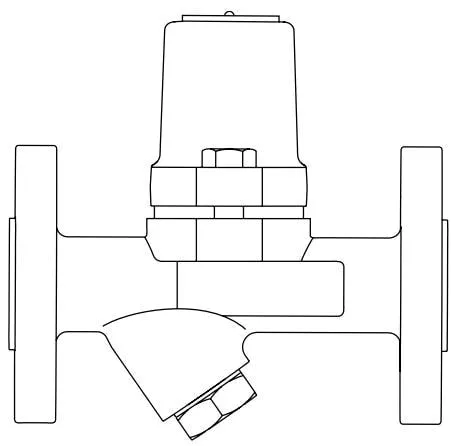
SMC32, SMC32F, SMC32Y and SMC32YF are inline, maintainable carbon steel bimetallic steam traps.
SMC32 and SMC32F incorporate flat strainers, while SMC32Y and SMC32YF incorporate cylindrical Y-type strainers.
SMC32F has an inline connection, where the letter “F” denotes integral flanges.
All pressure-bearing components are supplied by TÜV-certified suppliers, and their manufacturing processes comply with AD-Merkblatt WO/TRD100.
Standards:
This product complies with the European Pressure Equipment Directive 97/23/EC.
Certification:
This product is available with an EN 10204 3.1 certificate. Note: Please specify this requirement when ordering.
Note: For further information, see the following technical documents.
| SMC32 and SMC32Y | TI-P076-10 |
| SMC32F and SMC32YF | TI-P076-17 |
2.2 Sizes and Pipe Connections
½”, ¾” and 1” threaded BSP or NPT connections
½”, ¾” and 1” socket weld connections to BS 3799
½”, ¾” and 1” butt weld connections to EN 12 627
DN15, DN20 and DN25 flanged connections to EN 1092 PN40,
ASME B 16.5 Class 150, ASME B 16.5 Class 300, JIS / KS 10K and JIS / KS 20K.
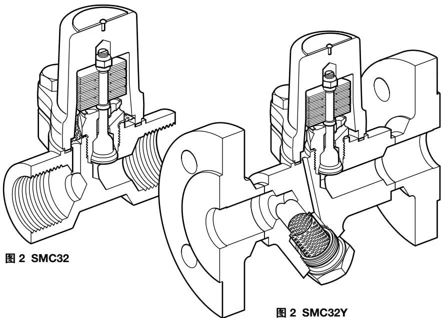
Figure 2 SMC32
Figure 2 SMC32Y
2.3 SMC32 and SMC32Y - Operating Range (ISO 6552)
Pressure psi g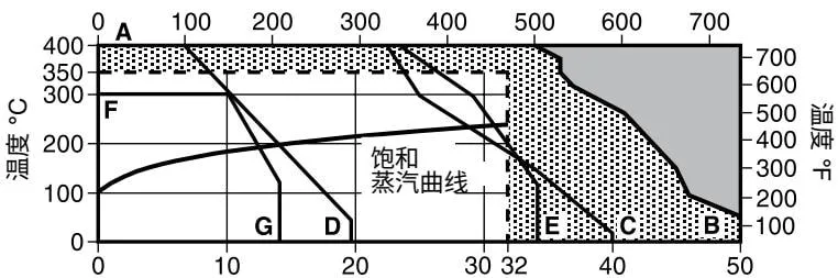
Pressure bar g

This product must not be used in this region.

Use of this product in this region may cause damage to internal components.
A - B Threaded, socket weld, butt weld and ASME 300 flanged
A - C EN 1092 PN40 flanged
A - D ASME 150 flanged
A - E JIS/KS 20K flanged
F - G JIS/KS 10K flanged
| Body design conditions | PN40 | ||
| PMA | Maximum allowable pressure | 50 bar g @ 50 °C | (725 psi g @ 122 °F) |
| TMA | Maximum allowable temperature | 400 °C @ 35 bar g | (752 °F @ 507 psi g) |
| Minimum allowable temperature | -60 °C | (-76 °F) | |
| PMO | Maximum operating pressure for saturated steam | 32 bar g | (464 psi g) |
| TMO | Maximum operating temperature | 350 °C @ 32 bar g | (662 °F @ 464 psi g) |
| Minimum operating temperature | 0 °C | (32 °F) | |
| Note: For applications at lower temperatures, please contact Spirax Sarco. | |||
| Maximum design cold hydraulic test pressure: | 75 bar g | (1088 psi g) | |
2.4 SMC32F and SMC32YF - Operating Range (ISO 6552)
Pressure psi g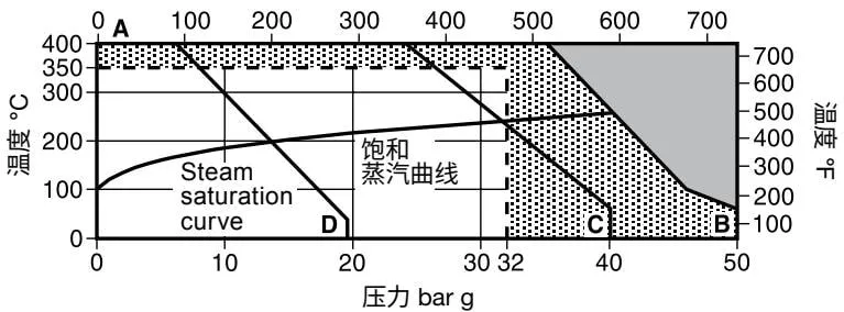

This product must not be used in this region.

Use of this product in this region may cause damage to internal components.
A - B ASME 300 flanged
A - C EN 1092 PN40 flanged
A - D ASME 150 flanged
| Body design conditions | ASME 300 | ||
| PMA | Maximum allowable pressure | 50 bar g @ 50°C | (725 psi g @ 122°F) |
| TMA | Maximum allowable temperature | 400°C @ 35 bar g | (752°F @ 507 psi g) |
| Minimum allowable temperature | -60°C | (-76°F) | |
| PMO | Maximum operating pressure for saturated steam | 32 bar g | (464 psi g) |
| TMO | Maximum operating temperature | 350°C @ 32 bar g | (662°F @ 464 psi g) |
| Minimum operating temperature | 0°C | (32°F) | |
| Note: For applications at lower temperatures, please contact Spirax Sarco. | |||
| Maximum design cold hydraulic test pressure: | 75 bar g | (1088 psi g) | |
3. Installation
Note: Read the safety information in Section 1 carefully before installation.
Before installation, check the installation and maintenance instructions, nameplate and technical documentation to ensure that this product is suitable for the site conditions.
3.1 Check the materials, pressure and temperature ratings, including their maximum allowable values. If the maximum allowable values are lower than those of the system, ensure that a safety device is installed to prevent overpressure.
3.2 Select the correct installation location and flow direction.
3.3 Before installing on steam or other high-temperature fluid pipelines, remove all protective covers from the connections and the protective tape from the nameplate.
3.4 This steam trap can be installed in any orientation, either horizontal or vertical, but preferably with a drop leg, typically 150 mm, upstream of the trap. See Figure 3.
Note: Without a drop leg, steam may reach the trap above the condensate in the pipeline at low loads.
Bimetallic steam traps are recommended for applications where subcooled condensate discharge is acceptable. Therefore, if immediate condensate removal is required, install a suitable uninsulated cooling section upstream of the trap. The cooling section must be at least 1 - 2 m (3 - 6 ft) long.
3.5 When condensate is discharged into a pressurized condensate return system, always install a check valve at the trap outlet. This is common in rising condensate lines. The check valve prevents condensate backflow when the system pressure drops or the system shuts down. As shown in Figure 3, use a Spirax Sarco DCV41 check valve.
3.6 Open the isolation valve slowly until system pressure is reached.
3.7 Check for leakage and correct operation.
3.8 Ensure sufficient clearance is available to remove the cover and strainer for maintenance. A minimum clearance of 51 mm is required to remove the cover, and 28 mm is required to remove the strainer on SMC32Y and SMC32YF.
3.9 When the steam trap discharges into a pressurized condensate return system, the discharge temperature will be reduced. For further information, contact Spirax Sarco.
3.10 Welding to the pipeline - the bimetallic element does not need to be removed from the steam trap during electric welding. For detailed welding procedures, refer to applicable national and international welding standards.
Note: If the steam trap discharges to atmosphere, ensure that discharge is directed to a safe location, as the discharged condensate may be at 100°C (212°F).
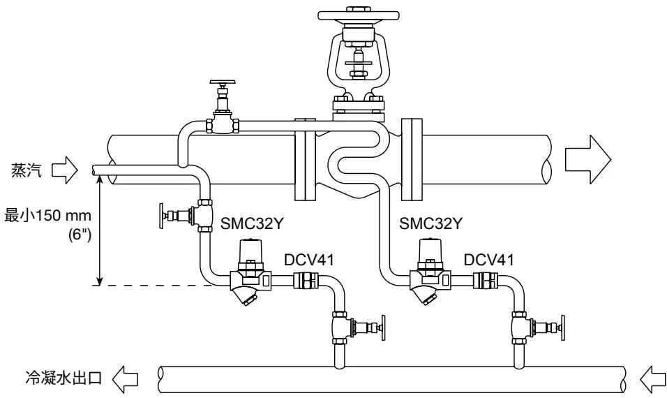
Figure 3 Non-critical tracing
4. Commissioning
After installation or maintenance, ensure that the system functions correctly by testing the alarm or protective devices first.
5. Operation
The operating principle of SMC bimetallic steam traps is based on two opposing forces acting on the valve: the opening force generated by system pressure and the closing force generated by condensate temperature acting on the bimetallic element. During operation, SMC traps do not leak steam and automatically discharge air, non-condensable gases and large quantities of condensate rapidly during system start-up.
6. Maintenance
Note: Carefully read the safety information in Section 1 before performing maintenance.
Warning: The cover gasket contains a very thin stainless steel support ring. Careless handling may result in injury.
6.1 General Information
Before servicing the steam trap, isolate the valves upstream and downstream of the trap and safely reduce the pressure to atmospheric pressure. Allow sufficient time for the trap to cool down gradually. When reassembling the steam trap, ensure that all mating surfaces are clean. Provided that the safety procedures are observed, the steam trap can be serviced while installed in the pipeline. It is recommended to replace gaskets and spare parts during every maintenance operation. Ensure that the correct tools and necessary protective equipment are used at all times. Upon completion of maintenance, slowly open the isolation valves and check for leakage.
6.2 Replacing the Bimetallic Element
Do not remove the locking nut or dismantle the bimetallic assembly, as this will affect steam trap operation.
- Loosen the two cover bolts (9) and remove the cover (1) from the body (8).
- Remove the complete bimetallic element assembly from the valve seat (3).
- Clean or replace the strainer (5) as required (SMC32 and SMC32F only).
- Replace the bimetallic element and tighten the valve seat (3) to the recommended torque (see Table 1).
- It is recommended to fit a new cover gasket (7), then refit the cover (1).
Note: Always tighten the cover bolts (9) to the recommended torque (see Table 1).
6.3 Cleaning and Replacing the Y-Type Strainer Screen (SMC32Y and SMC32YF):
- Remove the strainer cap (10) and take out the strainer screen (5).
- Clean or replace the strainer screen as required. It is recommended to fit a new strainer cap gasket (11), then install the strainer cap (10) on the body (8), ensuring that the strainer screen is properly aligned during installation.
- Apply a small amount of high-temperature anti-seize compound to the threads and tighten the cap to the torque specified in Table 1.
6.4 Cleaning and Replacing the Strainer Screen (SMC32 and SMC32F):
- Loosen the two cover bolts (9) and remove the cover (1) from the body (8).
- Remove the complete bimetallic element assembly from the valve seat (3).
- Clean or replace the strainer screen (5) as required.
- Replace the bimetallic element and tighten the valve seat (3) to the recommended torque (see Table 1).
- It is recommended to fit a new cover gasket (7), then refit the cover (1).
Note: Always tighten the cover bolts (9) to the recommended torque (see Table 1).
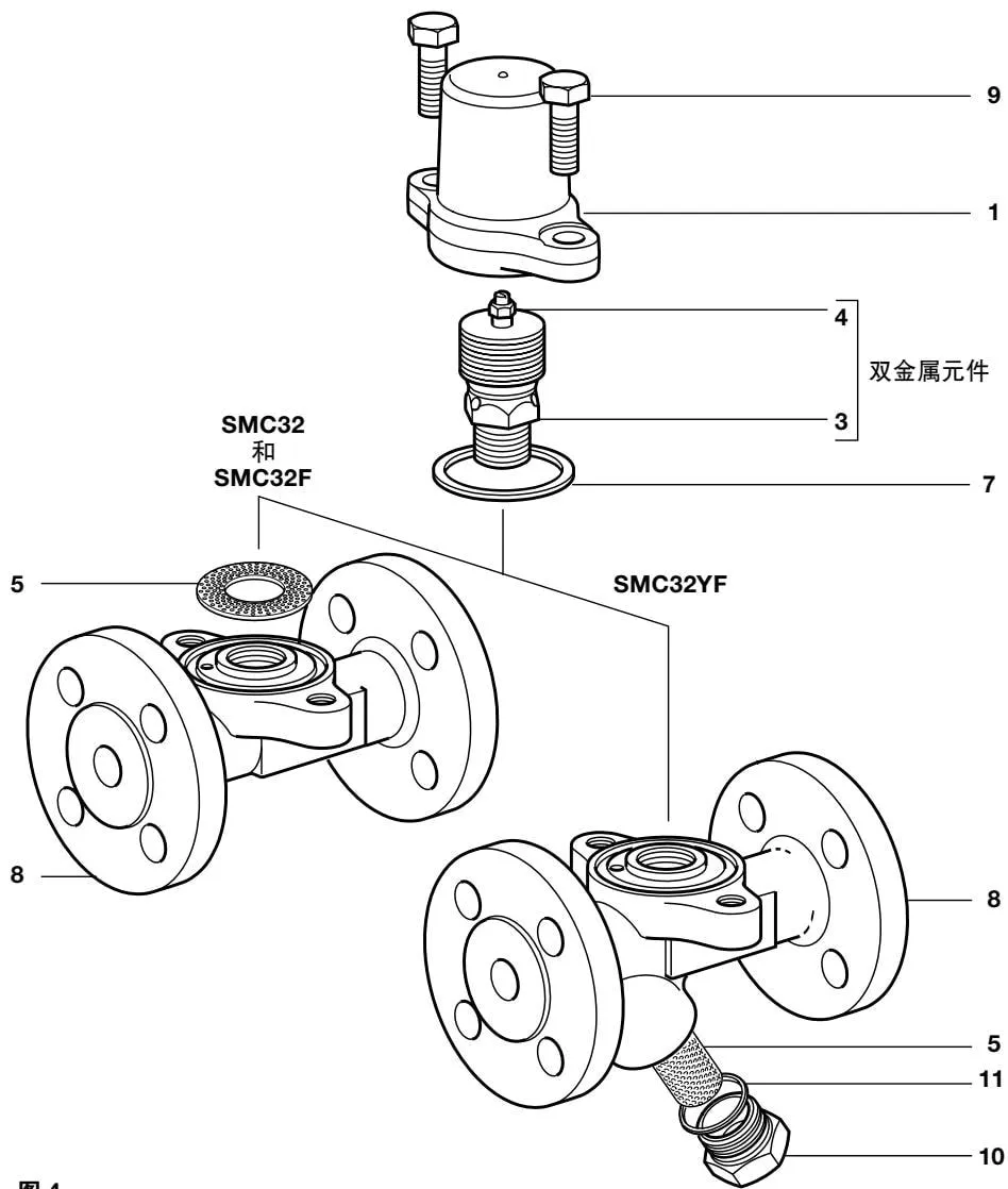
Figure 4
7. Spare Parts
Available spare parts are shown in solid lines. Parts shown in dashed lines are not available as spare parts.
Available Spare Parts
| Bimetallic element | 2,3,4,6 | ||
| Strainer screen | SMC32 and SMC32F | (3 pieces) | 5 |
| Strainer screen and gasket | SMC32Y and SMC32YF | (1 of each) | 5,11 |
| Cover gasket set | (3 pieces) | 7 | |
| Strainer cap gasket | (3 pieces) | 11 |
Ordering Spare Parts
Order spare parts using the available spare parts list above, and specify the steam trap model and size.
Warning: Do not remove the locking nut or dismantle the bimetallic assembly, as this will affect steam trap operation.
Example:
1 - ½” SMC32 bimetallic
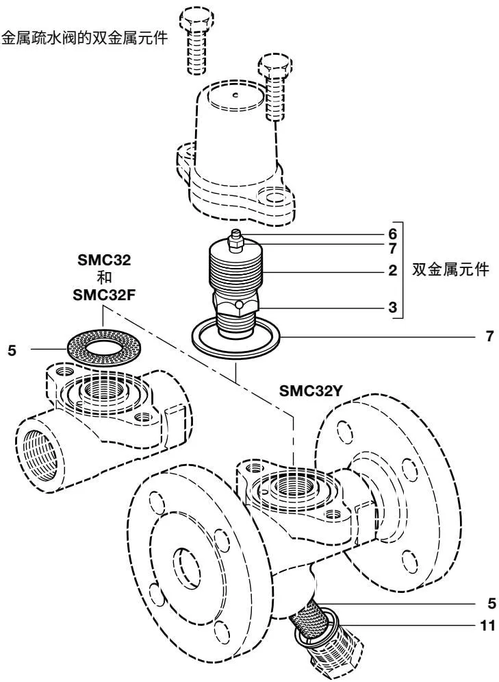
Figure 5