

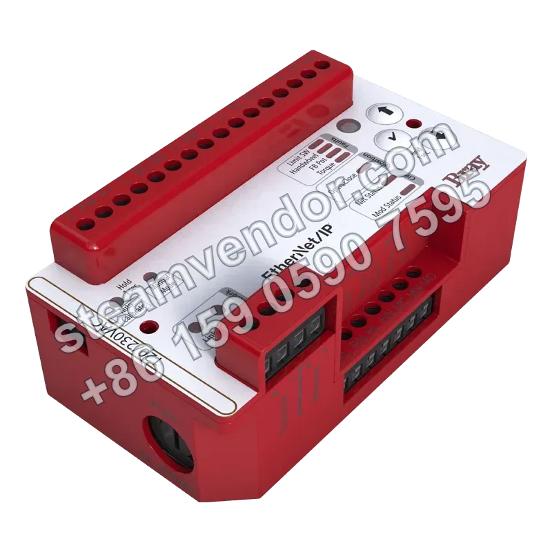
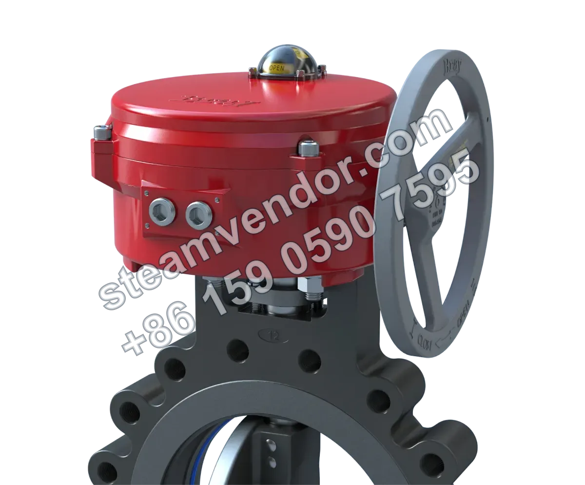
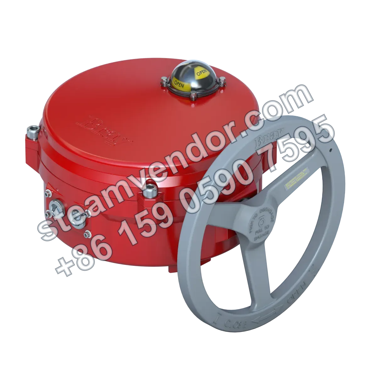
Bray Bray Series 70 lightweight electric actuators for quarter-turn valve control provide convenient on/off or modulating control of quarter-turn valves. Available power supply options include 120/230 VAC and 24V, with support for modulating inputs such as 4–20 mA and 0–10V, as well as optional DeviceNet and EtherNet/IP communication. With NEMA 4/4X and IP65/IP67 protection ratings, ISO 5211 mounting, a standard 90° rotation angle, and handwheel declutch override, they are suitable for remote on/off and modulating control of quarter-turn valves in water treatment piping and industrial automation networks.
Electric Actuator Series 70 product image
1 / 3
Bray Series 70 Lightweight Electric Actuators (Quarter-Turn Valve Control)
Lightweight electric actuators supporting modulating control of quarter-turn valves
Genuine product assurance
We can help verify product data and purchasing details.
Model confirmation
Confirm model, connection and key options before ordering.
After-sales support
After-sales communication support is provided according to the order agreement.
Specifications
- Output Torque
- 120/230V: 300 to 18,000 in-lb (34-2,034 Nm); 24V: 600, 2,000, 5,000 in-lb (68, 226, 565 Nm)
- Control Type
- On/off control, modulating control
- Power Supply Voltage
- 120, 230 VAC 50/60 Hz, single-phase; 24V AC/DC; 70-NXT: 120/220 VAC 50/60 Hz, 24V AC/DC
- Input Signal
- On/off: 120/230 VAC or 24V AC/DC; modulating: 4-20 mA, 0-10V, 0-5V, 2-10V
- Communication Protocols
- DeviceNet, EtherNet/IP
- Enclosure Ratings
- NEMA 4, NEMA 4X, IP65, IP67
- Operating Temperature Range
- -20°F (-29°C) to 150°F (+65°C)
- Mounting Standard
- ISO 5211
- Compatible Valve Type
- Quarter-turn valves
- Motor Type
- 120/230 VAC: single-phase reversible permanent split-capacitor motor; 24V: permanent-magnet brushed DC motor
- Limit Switches
- Two SPDT mechanical switches standard; additional auxiliary switches available, up to six total; optional torque switch
- Standard Rotation Angle
- 90°
- Mechanical Overtravel
- 5°
- Manual Override
- All models include a declutchable handwheel manual override as standard
- Conduit Entries
- Two entries, supporting NPT or metric threads
- Certifications
- Most 120V models are UL, CSA, and CE certified; 70-24V is CE certified
Application scenarios
Quarter-turn valve automation for water and wastewater treatment pipelines
Used for quarter-turn valves in water and wastewater treatment systems that comply with ISO 5211 mounting requirements, providing remote on/off or modulating control. Supports modulating inputs such as 4-20 mA and 0-10V, with NEMA 4, NEMA 4X, IP65, or IP67 protection ratings available.
Quarter-turn valve control in industrial automation networks
Used to operate quarter-turn valves in automation control systems, providing on/off or modulating control. The 70-NXT configuration supports DeviceNet and EtherNet/IP communication protocols for integration into industrial networks.
Selection points
Low-Profile, Lightweight Quarter-Turn Drive
The Series 70 is a lightweight electric actuator for quarter-turn valves, featuring a low-profile, lightweight design and an output torque range of 34 to 2034 Nm.
On/Off and Modulating Control Options
The Series 70 is available with on/off and modulating control. Modulating control supports 4-20 mA, 0-10V, 0-5V, and 2-10V input signals, with DeviceNet and EtherNet/IP communication options available.
Declutchable Handwheel Manual Override on All Models
All models are standard with a declutchable handwheel manual override for manual operation and on-site commissioning.
Maintenance Layout for Easy Wiring and Limit Adjustment
The terminal block enables direct wiring, while travel limit cams can be adjusted by hand or with a screwdriver without interference from other components.
Multiple Enclosure Protection Ratings
The product is available with NEMA 4, NEMA 4X, IP65, and IP67 protection ratings for selection according to project environmental protection requirements.
Limit and Auxiliary Switch Expansion
The product is standard with two SPDT mechanical limit switches. Auxiliary switches can be added for a maximum total of six, and torque switches are available as an option.
Installation & maintenance notes
Mounting Interface and Valve Compatibility
Install the Bray Series 70 actuator on a quarter-turn valve in accordance with the ISO 5211 mounting standard, and verify compatibility between the actuator and valve mounting interfaces.
Installation Ambient Temperature Limits
The ambient temperature at the installation location must be within the specified operating temperature range of -29°C to +65°C.
Power Supply and Control Signal Compatibility
Before wiring, confirm the power supply voltage and control mode for the purchased model, and ensure that the on/off or modulating control input matches the signal types supported by that model.
FAQ
How does the Series 70 electric actuator work?
The Series 70 uses an integrated motor to drive a worm and worm wheel output, providing valve on/off or modulating control. Output torque ranges from 300 in-lb to 18,000 in-lb, and different controllers enable on/off, analog, or servo modulating control for applications requiring low maintenance and a compact footprint.
Which key parameters should be considered when selecting this series?
Consider output torque, control options, supply voltage, enclosure rating, input signal, and valve compatibility to ensure compatibility with the existing system interfaces, power conditions, and environmental requirements. The specific configuration must be confirmed based on the actual model and application conditions.
What common control methods and interfaces are available for the Series 70?
Primary control options include an on/off relay board, a 24VAC/DC controller, and a Servo NXT controller. Communication protocols support Servo NXT DeviceNet and EtherNet/IP for integration with PLCs or automation systems.
What installation and field maintenance considerations apply to the Series 70?
Follow the ISO 5211 mounting interface standard. The equipment features a low-profile, weatherproof design, and the manual override allows manual operation when required. Field maintenance primarily involves checking the limits, terminal connections, and protective components to ensure that sealing and enclosure ratings meet site requirements. Specific procedures must be confirmed for the actual model and application conditions.
How reliable is this series in extreme environments?
The equipment is UL, CSA, and CE certified. Its housing uses robust structures and materials with high enclosure protection, corrosion resistance, and impact-resistant design, making it suitable for demanding environments while emphasizing minimal maintenance requirements. Specific performance must be confirmed for the actual model and application conditions.
Documents
Product Brochure - Actuators and ControlsProduct information · EnglishProduct Brochure - Valve Automation Center (VAC)Product information · EnglishSales Data Sheet - Series 70 Electric Actuator Installation InstructionsProduct information · EnglishIOM Manual - Series 70 Electric ActuatorsManual · EnglishIOM Manual - Series 70 24V On/Off NXT ControllerManual · EnglishIOM Manual - Series 70 Servo NXT EtherNet/IPManual · EnglishIOM Manual - Series 70 Servo NXT Modulating ControllerManual · EnglishIOM Manual - Series 70 NXT Electric ActuatorsManual · EnglishIOM Manual - Series 70 24V Electric ActuatorsManual · EnglishIOM Manual - Actuadores Eléctricos Serie 70Manual · EnglishIOM Manual - Serie 70 Control Modulante Servo NXTManual · EnglishQuick Start Guide - Series 70 Electric ActuatorsProduct information · EnglishTechnical Sales Manual - Series 70 Electric ActuatorsManual · EnglishSales Data Sheet - Series 70 Electric ActuatorsProduct information · ChineseSales Data Sheet - typ 70 elektrické pohonyProduct information · EnglishSales Data Sheet - Series 70 Electric ActuatorsProduct information · EnglishSales Data Sheet - Series 70 Servo NXT EtherNet/IP Electric ActuatorsProduct information · EnglishSales Data Sheet - Hazardous Location Control DevicesProduct information · EnglishSales Data Sheet - Actuadores Eléctricos Serie 70Product information · EnglishSales Data Sheet - Actuador Eléctrico Serie 70 Servo NXT EtherNet/IP™Product information · EnglishRecommended Specification - Series 70 Electric ActuatorsProduct information · EnglishRecommended Specification - Actuador Eléctrico Serie 70Product information · English