
1. Safety information
Safe operation of this product can only be guaranteed if it is properly installed, commissioned, used, and maintained by qualified personnel in compliance with the operating instructions (see Section 1.11). General installation and safety instructions for pipeline and plant construction must also be followed, together with the proper use of tools and appropriate safety equipment.
1.1 Intended use
Refer to the Installation and Maintenance Instructions, nameplate, and technical documentation to ensure that the product is suitable for its intended use. This product complies with the requirements of the European Pressure Equipment Directive 97/23/EC and may bear the CE mark where required. The product falls within the following Pressure Equipment Directive category:
I) The product is designed for use with Group 2 fluids under the Pressure Equipment Directive, including steam, air, and water/condensate. Contact Spirax Sarco if the product is to be used with other fluids. II) Ensure that the product material is suitable for the operating conditions and that the maximum and minimum system pressures and temperatures are within the product’s design limits. If the product’s maximum operating limits are lower than the system operating conditions, or if product failure could result in dangerous overpressure or overtemperature, install a safety device to prevent such hazards. III) Ensure that the product is installed correctly and that the inlet and outlet connections are not reversed. IV) Spirax Sarco products are not designed to withstand external stresses. The installer is responsible for preventing external forces within the system from being imposed on the product. V) Before installing the product in a steam or other high-temperature system, remove the protective covers from all connections and the protective film from the nameplate.
1.2 Access
Ensure that there is adequate access around the installed product. If required, provide a suitable working platform before operating the product. Arrange suitable lifting equipment if required.
1.3 Lighting
Ensure adequate lighting, particularly where detailed or complex work is required.
1.4 Hazardous liquids or gases in the pipeline
Consider what is currently in the pipeline and what fluids it may contain. Beware of flammable substances, substances hazardous to health, and substances at extreme temperatures.
1.5 Hazardous working environment
Consider explosion hazards, oxygen deficiency in tanks or confined spaces, hazardous gases, extreme temperatures, hot surfaces, fire hazards such as those arising during welding, excessive noise, and moving machinery.
1.6 The system
Consider the effect of the proposed work on the complete system. Before carrying out any action, such as closing an isolation valve or switching off an electrical supply, determine whether it could place any other part of the system or any personnel at risk.
Hazards may include the isolation of vents or protective devices and the disabling of control or alarm equipment. Open and close isolation valves gradually to avoid system shock.
1.7 Pressure systems
Ensure that all pressure is isolated and safely vented to atmospheric pressure. Consider double isolation and bleed, and lock or label closed valves. Do not assume that the system is fully depressurized merely because the pressure gauge indicates zero.
1.8 Temperature
After isolation, allow the product to cool to ambient temperature to prevent burns.
1.9 Tools and replacement parts
Before starting work, ensure that suitable tools and replacement parts are available. Use only genuine Spirax Sarco replacement parts.
1.10 Protective clothing
Consider whether personnel carrying out the work or others nearby require protective clothing to guard against hazards such as chemicals, extreme temperatures, radiation, noise, falling objects, and injury to the eyes or face.
1.11 Permit to work
All work must be carried out or supervised by suitably competent personnel. Installation and operating personnel must be trained in the correct use of the product in accordance with the Installation and Maintenance Instructions.
Where a formal permit-to-work system is in force, it must be followed. Where no such system exists, a responsible person must understand the nature of the work and, where necessary, appoint an assistant whose primary responsibility is safety.
Post warning notices where necessary.
1.12 Handling
Manual handling of large or heavy products may present a risk of injury. Lifting, pushing, pulling, carrying, or supporting a load using bodily force can cause injury, particularly to the back. Assess the task, the individual, the load, and the working environment, and use appropriate handling methods according to site conditions.
1.13 Residual hazards
During normal operation, the external surface of the product may become very hot. When operated at the maximum permissible temperature, the surface temperature may reach 500°C (932°F).
This product is not self-draining. Exercise caution when removing or relocating it from its installed position. Refer to the maintenance instructions.
1.14 Freezing
Non-self-draining products exposed to ambient temperatures below freezing must be protected against frost where necessary.
1.15 Disposal
Unless otherwise stated in the Installation and Maintenance Instructions, this product is recyclable and presents no ecological hazard when disposed of properly.
1.16 Returning products
In accordance with EC health, safety, and environmental legislation, customers and distributors returning products must provide information on any hazards and precautions required due to residual contamination or mechanical damage that could present a health, safety, or environmental risk. This information must be provided in writing, including health and safety data sheets identifying any known or potential hazards.
1.17 Safety information for grey cast iron products in steam systems
Grey cast iron products are commonly used in steam and condensate systems. They are safe when installed and used in accordance with recognized steam engineering practices. However, due to their mechanical properties, grey cast iron products are more susceptible to damage than products made from materials such as ductile iron or stainless steel. The following guidance will help prevent waterhammer and ensure safe operation of the steam system.
Safe handling
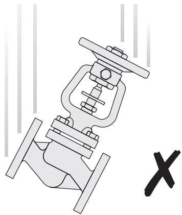
Grey cast iron is a brittle material. If a product is dropped from a height during installation, it must be thoroughly inspected and pressure-tested to confirm that it is undamaged before being returned to service.
Prevention of waterhammer
Steam main drainage:
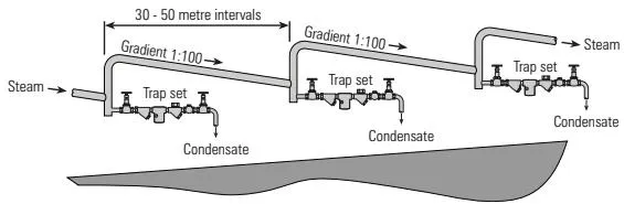
Recommended and incorrect steam main arrangements:
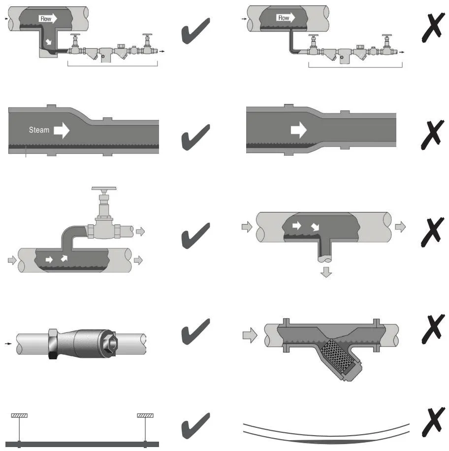
Prevention of tensile stress
Incorrect pipe alignment:
Initial installation or reassembly after maintenance:
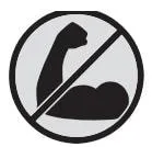

Do not overtighten
Use the correct torque values
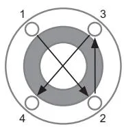
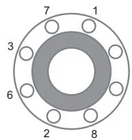
Tighten flange bolts in the sequence shown
to ensure an even bolt load and a secure connection
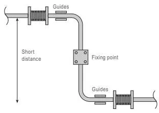
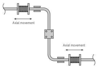
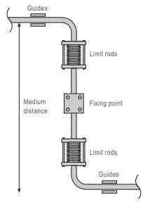
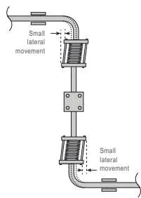
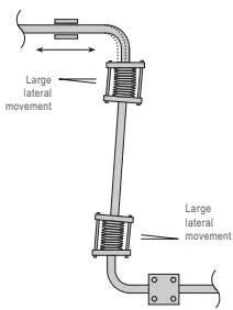
Thermal expansion
2. Product information
2.1 General description
CA10S (3/4” screwed connection)
The CA10S is a ball float automatic drain trap for air and other gas systems. It has a cast iron body and a stainless steel valve mechanism, making it suitable for high-temperature applications or applications involving corrosive condensate where rubber components cannot be used.
CA14 and CA14S
(1/2” and 3/4” screwed connections, and DN15, DN20, and DN25 flanged connections)
The CA14 is a ball float automatic drain trap for air systems. The body and cover are manufactured from ductile iron, and the complete assembly is fully maintainable.
The standard CA14 is fitted with a VITON valve mechanism.
The CA14S is supplied with a stainless steel valve mechanism.
(DN15, DN20, and DN25 flanged connections)
The cover can be drilled and tapped 1/2” BSP or NPT for connection of a balance line. Flanged versions are available with right-to-left flow (CA14 R-L) or left-to-right flow (CA14 L-R).
CA14S (DN40 and DN50 flanged connections)
The CA14S is a cast iron ball float trap for air or gas systems. It has a stainless steel valve mechanism and flanged connections and is installed horizontally. The cover can be drilled and tapped 1/2” BSP or NPT for connection of a balance line.
Optional feature:
Drain tapping: The body can be drilled and tapped 3/8” BSP or NPT for installation of a drain valve.
Available option
Drain ball valve connection: The cover can be drilled and tapped 3/8” BSP or NPT for connection of an external drain valve.
Note
For further information, refer to the following table:
| Product | Size | Connection | Material | Section | Technical information |
|---|---|---|---|---|---|
| CA10S | 3/4” | Screwed | Cast iron | 2.2 | TI-P148-15 |
| CA14 | 1/2” and 3/4” | Screwed | SG iron | 2.3 | TI-P148-36 |
| CA14S | 1/2” and 3/4” | Screwed | SG iron | 2.3 | TI-P148-36 |
| CA14 | DN15, DN20, and DN25 | Flanged | SG iron | 2.4 | TI-P148-12 |
| CA14S | DN15, DN20, and DN25 | Flanged | SG iron | 2.4 | TI-P148-12 |
| CA14S | DN40 and DN50 | Flanged | Cast iron | 2.5 | TI-P148-35 |
2.2 CA10S - Cast Iron
Figure 1: 3/4” BSP threaded connection
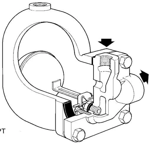
Sizes and Pipe Connections
3/4” BSP threaded connection (BS21 parallel) or NPT
A 1/2” threaded hole is available for connecting a balance pipe.
Pressure-Temperature Limits
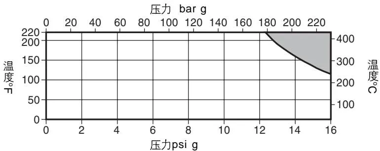
The product must not be used in this region.
| Parameter | Value |
|---|---|
| Body design conditions | PN16 |
| PMA maximum allowable pressure (120°C) | 16 bar g |
| TMA maximum allowable temperature | 250°C |
| Minimum allowable temperature | 0°C |
| PMO maximum operating pressure (120°C) | 16 bar g |
| TMO maximum operating temperature (12.1 bar g) | 220°C |
| Minimum operating temperature | 0°C |
| △PMX maximum differential pressure (dependent on the specific gravity of the condensate being discharged) | See table below |
| △PMN minimum differential pressure | 0.1 bar |
| Maximum design cold hydraulic test pressure | 24 bar g |
| Specific gravity | 1.0 | 0.9 | 0.8 | 0.7 | Minimum 0.6 |
|---|---|---|---|---|---|
| △PMX | 14.0 | 13.8 | 11.7 | 8.6 | 5.0 |
2.3 CA14 and CA14S - Ductile Iron
Figure 2: 1/2” BSP threaded connection
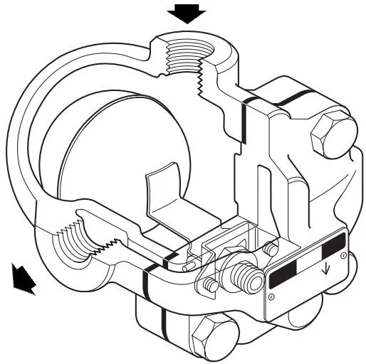
Sizes and Pipe Connections
1/2” and 3/4” BSP or NPT threaded connections
Pressure-Temperature Limits
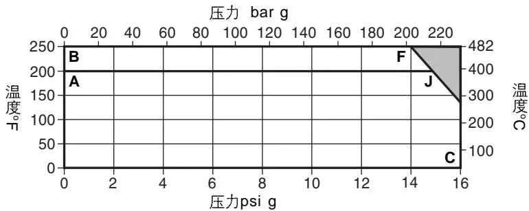

The product must not be used in this region.
A-J-C CA14 with BSP or NPT threaded connection. B-F-C CA14S with BSP or NPT threaded connection.
| Parameter | Value |
|---|---|
| Body design conditions | PN16 |
| PMA maximum allowable pressure (120°C) | 16 bar g |
| TMA maximum allowable temperature | 250°C |
| Minimum allowable temperature | 0°C |
| PMO maximum operating pressure (120°C) | 16 bar g |
| TMO maximum operating temperature - CA14 (14.7 bar g) | 200°C |
| TMO maximum operating temperature - CA14S (13.9 bar g) | 250°C |
| Minimum operating temperature | 0°C |
| △PMX maximum differential pressure (dependent on the specific gravity of the condensate being discharged) | See table below |
| △PMN minimum differential pressure | 0.1 bar |
| Maximum design cold hydraulic test pressure | 24 bar g |
| Specific gravity | 1.0 | 0.9 | 0.8 | 0.7 | Minimum 0.6 |
|---|---|---|---|---|---|
| △PMX | 14.0 | 14.0 | 14.0 | 9.0 | 5.0 |
2.4 CA14 and CA14S - Ductile Iron
Figure 3: DN20 flanged connection
Sizes and Pipe Connections
DN15, DN20, and DN25
Standard flanges to EN 1092 PN16
ANSI 150 and JIS/KS 10
A 1/2” tapped hole is available for connecting a balance pipe.
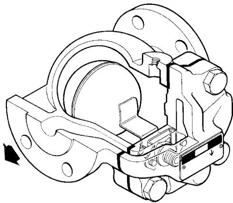
Pressure-Temperature Limits
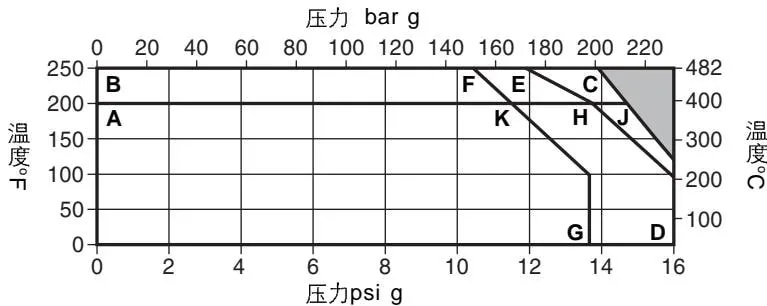
The product must not be used in this region.
A-J-D CA14 with PN16 flanged connection A-K-G CA14 with JIS/KS 10 flanged connection A-H-D CA14 with ANSI 150 flanged connection B-C-D CA14S with PN16 flanged connection B-F-G CA14S with JIS/KS 10 flanged connection B-E-D CA14S with ANSI 150 flanged connection
| Parameter | Value |
|---|---|
| Body design conditions | PN16 |
| PMA maximum allowable pressure (120°C) | 16 bar g |
| TMA maximum allowable temperature | 250°C |
| Minimum allowable temperature | 0°C |
| PMO maximum operating pressure (120°C) | 16 bar g |
| TMO maximum operating temperature - CA14 (14.7 bar g) | 200°C |
| TMO maximum operating temperature - CA14S (13.9 bar g) | 250°C |
| Minimum operating temperature | 0°C |
| △PMX maximum differential pressure (dependent on the specific gravity of the condensate being discharged) | See table below |
| △PMN minimum differential pressure | 0.1 bar |
| Maximum design cold hydraulic test pressure | 24 bar g |
| Specific gravity | 1.0 | 0.9 | 0.8 | 0.7 | Minimum 0.6 |
|---|---|---|---|---|---|
| △PMX | 14.0 | 14.0 | 14.0 | 9.0 | 5.0 |
2.5 CA14S
Figure 4: DN40 flanged connection
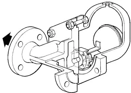
Sizes and Pipe Connections
DN40 and DN50, with flanges to EN 1092 PN16
ANSI B 16.1/BS 1560 Class 125 and JIS/KS 10K are available on request.
The body can be drilled and tapped with a 1/2” hole for connecting a balance pipe. Bodies with PN standard flanges are tapped with a BSP balance pipe connection; bodies with ANSI or JIS/KS standard flanges are tapped with an NPT balance pipe connection.
Pressure-Temperature Limits
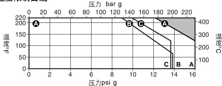

The product must not be used in this region.
A-A-A Flanged connection to EN 1092 PN16
A-B-B Flat-face flanged connection to ANSI B 16.1/BS 1560 Class 125
A-C-C Flanged connection to JIS/KS 10
| Parameter | Value |
|---|---|
| Body design conditions | PN16 |
| PMA maximum allowable pressure (at 120°C) | 16 bar g |
| TMA maximum allowable temperature | 220°C |
| Minimum allowable temperature | 0°C |
| PMO maximum operating pressure (at 120°C) | 16 bar g |
| TMO maximum operating temperature (at 12.2 bar g) | 220°C |
| Minimum operating temperature | 0°C |
| △PMX maximum differential pressure (dependent on the specific gravity of the condensate being discharged) | See table below |
| △PMN minimum differential pressure | 0.1 bar |
| Maximum design cold hydraulic test pressure | 24 bar g |
| Model | Specific gravity 1.0 | 0.9 | 0.8 | 0.7 | Minimum 0.6 |
|---|---|---|---|---|---|
| △PMX - CA14S-4.5 | 4.5 | 4.5 | 4.5 | 3.4 | 2.0 |
| △PMX - CA14S-10 | 10.0 | 9.5 | 6.8 | 5.5 | 3.4 |
| △PMX - CA14S-14 | 14.0 | 14.0 | 11.0 | 8.0 | 5.0 |
3. Installation
Note: Before installation, carefully read the safety information in Section 1.
Warning: The cover gasket and main valve assembly sealing ring of the CA14S contain thin stainless steel support rings that may cause personal injury if handled improperly.
Before installation, refer to the Installation and Maintenance Instructions, nameplate, and technical documentation to verify that the product is suitable for the intended application.
3.1 Check materials, pressure, and temperature
Check the materials, pressure, and temperature, including their maximum values, to determine whether the product’s maximum operating limits are lower than the system conditions. The system must also include a safety device to prevent overpressure.
3.2 Installation position and flow direction
Ensure the correct installation position and flow direction.
3.3 Remove the connection covers
Remove the covers from the connections.
3.4 CA10S, CA14, and CA14S (1/2” and 3/4” threaded connections)
The drain trap must be installed horizontally with the inlet at the top, allowing the float mechanism to rise and fall freely in the vertical direction. Figures 5, 6, and 7 show some typical installation arrangements.
CA14 and CA14S (DN15, DN20, DN40, and DN50 flanged connections)
The drain trap must be installed horizontally, allowing the float mechanism to rise and fall freely in the vertical direction. In this configuration, flow may be from left to right or from right to left.
Note: Figure 5 shows an installation without a balance line.
3.5 Drain trap arrangement and balance line
The drain trap must be installed below the point to be drained, with the arrow on the nameplate pointing downward. One advantage of this type of float drain trap in air systems is that it does not need to vent air to operate. However, because the trap does not vent air, air locking may occur in some applications. At low loads, such as compressed air main drainage applications, the air inside the body is displaced by water entering the body.
At high loads, such as cooler or vessel drainage applications, the air inside the body is not displaced, and a separate balance line is required. The balance line must be routed back to the upstream pressurized line. If air locking persists after repeated testing, a balance line must be installed.
A balance line may be used whenever there is any doubt.
Note: If the drain trap discharges to atmosphere, the discharged condensate may reach 100°C. Ensure that it is discharged to a safe location.
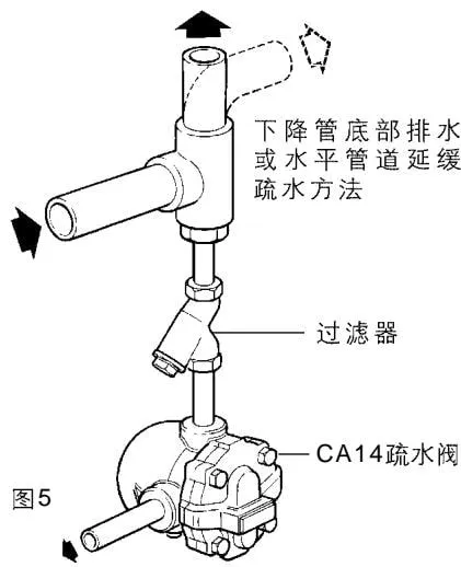
Figure 5: Drainage from the bottom of a drop leg or delayed drainage from a horizontal pipeline
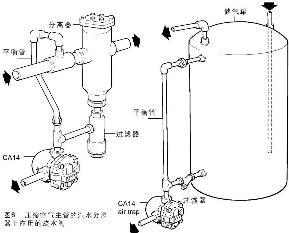
Figure 6: Drain trap installed on a compressed air main separator
Figure 7: Drain trap installed on a small air receiver
Figures 6 and 7: Installation arrangements with a balance line
4. Commissioning
After installation or maintenance, verify that the system is fully operational. Test any alarm or protective devices first.
5. Operation
The CA10 and CA14 float drain traps are continuous-discharge traps used to drain water from air and other gas systems. When liquid enters the main chamber of the trap, the float rises and the lever mechanism opens the main valve, allowing liquid to be discharged continuously from the system. When air or other gases enter the trap, the float drops and closes the main valve. A balance line is required to prevent air locking. The advantages of float drain traps include high instantaneous discharge capacity, tight shut-off, and resistance to water hammer and vibration.
6. Maintenance and Spares
6.1 CA10S (3/4 threaded connection)
Caution: Carefully read the safety information in Chapter 1 before carrying out maintenance.
Warning: The cover gasket contains a thin stainless steel support ring that may cause injury if not handled carefully.
Procedure:
- The trap can be serviced in the pipeline provided that it has been properly isolated.
- Ensure that all mating surfaces are clean during reassembly.
How to replace the main valve assembly
- Isolate the trap, remove the cover bolts (2), and remove the existing assembly (5, 6, 7, 8+12, 9, 10, 11).
- Apply a small amount of sealant to the threads and gasket (6), screw the new valve seat into the body (5), and tighten it to the recommended torque (see Table 1).
- Secure the support bracket (10) and pivot support bracket (11) with the assembly bolts (7), but do not tighten them.
- Install the float assembly (8+12) on the pivot support bracket (11) and insert the pin (9). Adjust the complete assembly to ensure that the valve disc and valve seat are fully aligned, then tighten the assembly screws to the recommended torque (see Table 1).
- Move the float up and down several times and check that the float valve disc and valve seat are fully aligned.
- Check that all sealing surfaces are clean and apply a small amount of anti-seize compound to the cover bolts (2).
- Refit the cover (4) using a new cover gasket (3).
- Tighten the cover bolts (2) to the recommended torque (see Table 1). After installation, slowly open the isolation valve.
- Check for leaks.
Table 1: Recommended torques
| Component | Spanner | Bolt specification | N m | (lbf ft) |
|---|---|---|---|---|
| 2 Cover bolts | 17 A/F | M10 x 30 | 29 - 32 | (19 - 23) |
| 5 Main valve seat | 17 A/F | M12 x 8 | 50 - 55 | (37 - 40) |
| 7 Float support bracket bolts | Cheesehead screw | M5 x 20 | 2.5 - 2.8 | (1.8 - 2.1) |
Spares
The solid lines in the figures below indicate the spare parts; parts shown with dashed lines are not supplied as spares.
Spare parts
| Spare part | Component numbers |
|---|---|
| Main valve assembly (with float) | 5,6,7,8+12,9,14,15,16 |
| Gasket set (set of 3) | 3,6 |
Ordering spares
Order spares using the descriptions above and specify the size and model.
Example: Main valve assembly for a 1-3/4” CA10S air trap.

Main valve assembly with float
Figure 8
6.2 CA14 and CA14S (1/2 and 3/4 threaded connections)
Caution: Carefully read the safety information in Chapter 1 before carrying out maintenance.
Warning: The cover gasket contains a thin stainless steel support ring that may cause injury if not handled carefully.
Procedure
- The trap can be serviced in the pipeline provided that it has been properly isolated.
- Ensure that all mating surfaces are clean during reassembly.
How to replace the CA14 main valve assembly
- Remove the cover bolts (2), lift off the cover (4), withdraw the pin (11), and remove the float and lever assembly (9) from the support bracket (10).
- Push out the main valve disc (5) and replace it with a new one.
- Fit a new cover gasket (3) and refit the cover (4).
- Tighten the cover bolts (2) to the recommended torque (see Table 1). After installation, slowly open the isolation valve. Check for leaks.
How to replace the CA14 and CA14S main valve assembly
- Remove the cover bolts (2) and lift off the cover (4).
- Remove the two retaining bolts (8) and take out the complete float assembly (9, 10, 11 and 5).
- Remove the main valve seat (6) and replace it with a new seat and gasket (7).
- Install a new float assembly (9, 10, 11 and 5) using the bolts (8), tightening them to the recommended torque (see Table 2).
- Fit a new cover gasket (3) and refit the cover.
- Tighten the cover bolts (2) to the recommended torque (see Table 2). After installation, slowly open the isolation valve.
- Check for leaks.
Table 2: Recommended torques
| Component | Spanner | Bolt specification | N m | (lbf ft) |
|---|---|---|---|---|
| 2 Cover bolts | 17 A/F | M10 x 30 | 47 - 50 | (35 - 37) |
| 6 Valve seat | 17 A/F | M12 | 50 - 55 | (36 - 40) |
| 8 Float support bracket bolts | Pozidrive | M4 x 6 | 2.5 - 3.0 | (1.8 - 2.2) |
Spares
The solid lines in the figures below indicate the spare parts; parts shown with dashed lines are not supplied as spares.
Spare parts
| Repair kit | Model | Component numbers |
|---|---|---|
| Repair kit | CA14 | 3,5,6,7,8(2 off),9,10,11 |
| CA14S | 3,6,7,8(2 off),9+5,10,11 | |
| Gasket set | CA14 | 3,5 |
Ordering spares
Order spares using the descriptions above and specify the size and model.
Example: Repair kit for a 1/2” CA14S air trap.
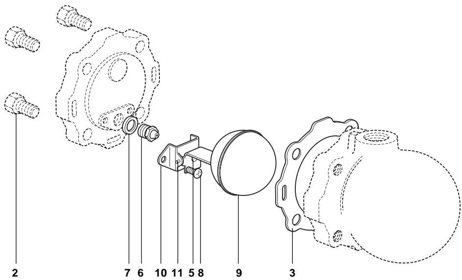
Figure 9
6.3 CA14 and CA14S (DN15, DN20 and DN25 flanged connections)
Caution: Carefully read the safety information in Chapter 1 before carrying out maintenance.
Warning: The cover gasket contains a thin stainless steel support ring that may cause injury if not handled carefully.
Procedure:
- The trap can be serviced in the pipeline provided that it has been properly isolated.
- Ensure that all mating surfaces are clean during reassembly.
How to replace the CA14 main valve assembly
- Remove the cover bolts (2), lift off the cover (4), withdraw the pin (11), and remove the float assembly (9) from the support bracket (10).
- Push out the main valve cone (5) and replace it with a new one.
- Fit a new cover gasket (3) and refit the cover.
- Tighten the cover bolts (2) to the recommended torque (see Table 3). After installation, slowly open the isolation valve. Check for leaks.
How to replace the CA14 and CA14S main valve assembly
- Remove the cover bolts (2) and lift off the cover (4).
- Remove the two retaining bolts (8) and take out the complete float assembly (5, 9, 10, 11, and 13 for DN25 only).
- Remove the main valve seat (6) and replace it with a new seat and gasket (7).
- Secure a new float assembly with the retaining bolts (8), tightening them to the recommended torque (see Table 3).
- Fit a new cover gasket (3) and refit the cover (4).
- Tighten the cover bolts (2) to the recommended torque (see Table 3). After installation, slowly open the isolation valve.
- Check for leaks.
Table 3: Recommended torques
| Component | Spanner | Bolt specification | N m | (lbf ft) |
|---|---|---|---|---|
| 2 Cover bolts | 17 A/F | M10 x 30 | 47 - 50 | (35 - 37) |
| 6 Valve seat | 17 A/F | M12 x 12 | 50 - 55 | (36 - 40) |
| 8 Float support bracket bolts | Pozidrive | M4 x 6 | 2.5 - 3.0 | (1.8 - 2.2) |
Spares
The solid lines in the figures below indicate the spare parts; parts shown with dashed lines are not supplied as spares.
Spare parts
| Repair kit | Model | Component numbers |
|---|---|---|
| Repair kit | CA14S | 3,6,7,8(2 off),5+9,10,11,13(DN25 only) |
| CA14 | 3,6,7,8(2 off),5+9,10,11 | |
| Gasket set | CA14 | 3,5 |
Ordering spares
Order spares using the descriptions above and specify the size and model.
Example: Repair kit for a DN15 CA14 air trap.
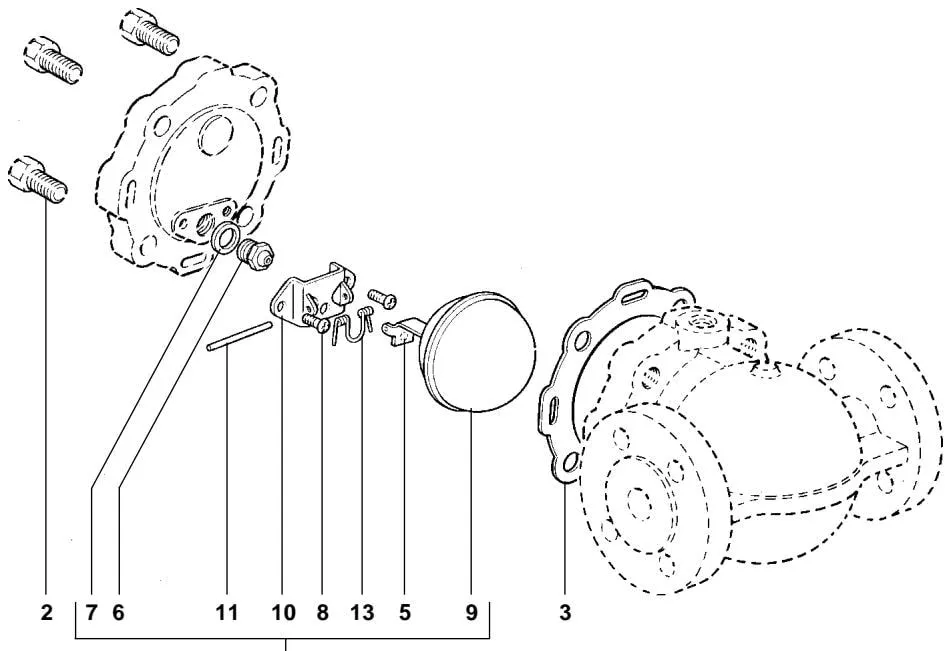
Main valve assembly
Component 13 is for DN25 only
Figure 10
6.4 CA14S (DN40 and DN50 flanged connections)
Caution: Carefully read the safety information in Chapter 1 before carrying out maintenance.
Warning: The cover gasket contains a thin stainless steel support ring that may cause injury if not handled carefully.
Procedure:
- The trap can be serviced in the pipeline provided that it has been properly isolated.
- Ensure that all mating surfaces are clean during reassembly.
How to replace the main valve assembly
- Remove the cover bolts (2) and lift off the cover.
- Remove the two bolts (6) and take out the complete float assembly (7, 8, 9, 10&11).
- Fit a new seal (14) and a new main valve seat (5), tightening the valve seat to the recommended torque (see Table 4).
- Attach the support bracket (9) and pivot support bracket (10) to the body using the retaining bolts (6), but do not tighten them.
- Attach the float arm (7&8) to the pivot support bracket (10) using the pin (11), and move the complete float assembly to ensure that the valve disc and valve seat are correctly aligned. Once aligned, tighten the retaining bolts (6) to the recommended torque (see Table 4).
- Move the float assembly up and down several times and check that the valve disc (7) and valve seat (5) are correctly aligned.
- Ensure that all mating surfaces are clean and apply a thin layer of anti-seize compound to the cover bolts (2).
- Tighten the cover bolts (2) to the recommended torque (see Table 4). Slowly open the isolation valve and allow the system to reach normal pressure.
- Check for leaks.
Table 4: Recommended torques
| Component | Size | Qty | Spanner | Bolt specification | N m | (lbf ft) |
|---|---|---|---|---|---|---|
| 2 Cover bolts | DN40 | 6 | 19 A/F | M12 | 60 - 66 | (44 - 48) |
| 2 Cover bolts | DN50 | 6 | 24 A/F | M16 | 80 - 88 | (58 - 65) |
| 5 Valve seat | DN40, DN50 | 1 | 17 A/F | M12 | 50 - 55 | (37 - 40) |
| 6 Support bracket bolts | DN40, DN50 | 2 | Cheesehead | M5 x 20 | 25 - 28 | (18 - 20) |
| 13 Float support bracket bolts | DN40 | 4 | 10 A/F | M6 | 10 - 12 | (7 - 9) |
| 13 Float support bracket bolts | DN50 | 4 | 13 A/F | M8 | 20 - 24 | (15 - 17) |
Spares
The solid lines in the figures below indicate the spare parts; parts shown with dashed lines are not supplied as spares.
Spare parts
| Spare part | Component numbers |
|---|---|
| Main valve assembly with float (*the anti-erosion eccentric orifice is fitted inside the valve during production and is not supplied as a spare) | 5,6,7+8,9,10,11,14 |
| Gasket set (set of 3) | 3,14 |
Ordering spares
Order spares using the descriptions above and specify the size and model.
Example: Repair kit for a DN40 CA14S-14 air trap.

Main valve assembly with float mechanism
Component 13 is for DN25 only
Figure 12