
For replacement of filter elements and seals in CSF16 / CSF16T stainless steel steam filters and sterile air filters. Before installation, commissioning, or maintenance, confirm that the product is suitable for the application by referring to the product nameplate, technical information sheet TI-P180-43, and actual operating conditions. For complete system installation instructions, refer to the relevant IM, such as IM-P180-42, and the product page: CSF16 / CSF16T Stainless Steel Steam Filters.
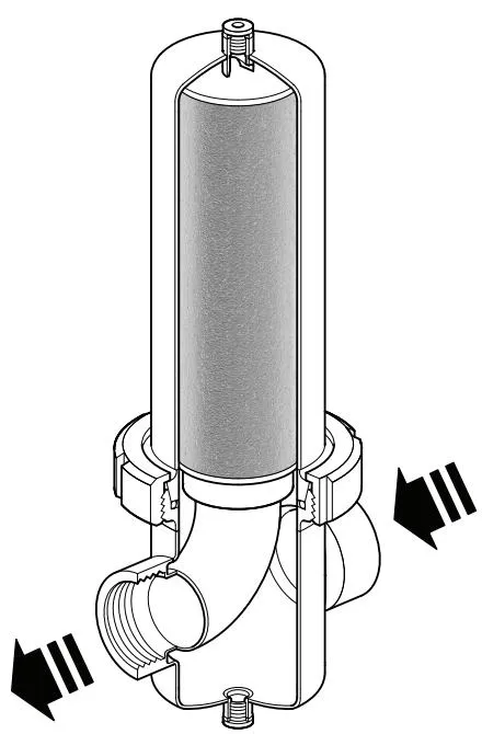
DN8–DN80 stainless steel steam filters

DN100 and DN150L stainless steel steam filters
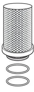
DN8–DN80 stainless steel sterile air filters

DN100 and DN150L stainless steel sterile air filters
1. Safety Information
Safe operation of this product can only be guaranteed if it is properly installed, commissioned, used, and maintained by qualified personnel in accordance with these instructions. General installation and safety requirements for pipeline and plant construction must also be observed, and tools and safety equipment must be used correctly.
This product is intended for connection to a process system capable of operating in compliance with EC1935 requirements. To minimize the risk of unintentionally added substances in the system, the end user must perform an appropriate CIP (clean-in-place) cycle before using the product in food-contact applications.
A complete list of all materials that may come into direct contact with food is provided in the Declaration of Conformity supplied with the product.
1.1 Intended Use
i) The filter elements have been validated for use in steam and compressed air systems.
ii) Ensure that the correct filter element and seal materials have been selected for the operating conditions.
iii) Remove all packaging and protective covers before installation, where applicable.
1.2 Access and Work Area
Ensure safe access and, where necessary, provide a properly guarded working platform. Arrange suitable lifting equipment where required.
1.3 Lighting
Ensure adequate lighting, particularly where detailed work is required.
1.4 Hazardous Liquids or Gases in the Pipeline
Before starting work, assess whether residual fluid is present in the pipeline and whether flammable materials, substances hazardous to health, or extreme temperatures are involved.
1.5 Hazardous Environment Around the Product
Consider potentially explosive areas, oxygen-deficient spaces such as tanks or pits, hazardous gases, extreme temperatures, hot surfaces, fire hazards such as welding, excessive noise, moving machinery, and other potential hazards.
1.6 Effects on the System
Assess the effects of the proposed work on the complete system. Determine whether actions such as closing isolation valves or carrying out electrical isolation could place other parts of the system or personnel at risk. Hazards may include isolation of vents or protective devices, or disabling controls and alarms. Open and close isolation valves slowly to avoid system shock.
1.7 Pressure Systems
Ensure that all pressure has been isolated and safely vented to atmospheric pressure. Do not assume that the system is fully depressurized even if the pressure gauge indicates zero.
1.8 Temperature
After isolation, allow sufficient time for the temperature to return to a safe level to avoid burns.
1.9 Tools and Consumables
Before starting work, ensure that suitable tools and/or consumables are available. Use only genuine Spirax Sarco spare parts.
1.10 Protective Clothing
Assess whether you and nearby personnel require protective clothing against chemicals, high or low temperatures, radiation, noise, falling objects, and hazards to the eyes and face.
1.11 Permit to Work
All work must be carried out or supervised by suitably competent personnel. Installation and operating personnel must be trained in the correct use of the product in accordance with these installation and maintenance instructions. Where a formal permit-to-work system is in place, it must be followed. Where no such system exists, it is recommended that a responsible person be kept informed of the work being performed, that an assistant whose primary responsibility is safety be assigned where necessary, and that warning notices be posted.
1.12 Handling
Manual handling of large and/or heavy products may cause injury. Lifting, pushing, pulling, carrying, or supporting loads manually may result in injury, particularly to the back. Assess the risks associated with the task, personnel, load, and working environment, and use an appropriate handling method.
1.13 Residual Hazards
During normal use, the external surface of the product may become extremely hot. Under the maximum permissible operating conditions, the surface temperature may exceed 220 °C (428 °F). Many products are not self-draining. Exercise particular care when dismantling or removing the product from the installation. Refer to the maintenance instructions.
1.14 Freezing
For products that are not self-draining, take precautions against freezing where ambient temperatures may fall below the freezing point.
1.15 Disposal
The product is recyclable. No ecological hazard is anticipated, provided that it is disposed of properly.
1.16 Returning Products
Customers and distributors are reminded that, under EC health, safety, and environmental legislation, when returning products to Spirax Sarco, they must provide written information on any health, safety, or environmental risks arising from contamination residues or mechanical damage, together with the precautions to be taken. This information must include health and safety data sheets for any identified hazardous or potentially hazardous substances.
2. Filter Element Installation and Replacement
Note: Before carrying out any maintenance, observe the safety information in Section 1.
2.1 General Information
Before maintenance, isolate the filter from the steam or air supply line and the return line, safely vent all pressure to atmospheric pressure, and allow the filter to cool. During reassembly, ensure that all mating surfaces are clean.
Warning: The differential pressure across CSF16-SE and CSF16-SF steam filter elements must not exceed 5 bar g.
For information on filter element service life, refer to Section 6.1 of IM-P180-42.
2.2 How to Replace the Filter Element
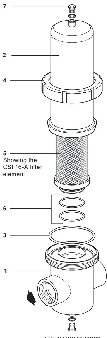
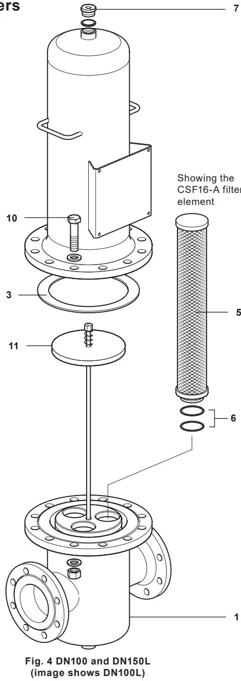
For component identification, refer to Figure 1, stainless steel steam filter, and Figure 2, stainless steel sterile air filter, below.
After completing the pipeline installation in accordance with the relevant instructions, follow the sequence below, with reference to the illustrations in the original instructions, to commission the CSF16 / CSF16T filter and replace the filter element.
Note: The upper and lower plugs are supplied hand-tight only. If the vent valve and steam trap have not been connected as recommended, tighten the plugs to the torque specified in Table 1.
Ensure that all isolation valves are closed.
Using a suitable wrench, loosen the housing locking ring (4) or housing bolts (10) securing the housing head (2) to the housing body (1), and then remove the housing head (2).
Carefully pull the filter element (5) vertically upward. If multiple filter elements are fitted, repeat this operation for each element.
Table 1 Recommended tightening torques
| Item | Part | Tool/specification | Torque (N·m) |
|---|---|---|---|
| 4 | Housing locking ring | Use a C-spanner | As required |
| 7 | Plug, DN8–DN80 | 6 mm hexagon, G 1/4” | 55 |
| 7 | Plug, DN100 and DN150L | 42 mm A/F, G1” | 138 |
| 10 | Bolt, DN100 | 30 mm A/F, M20 | 180 |
| 10 | Bolt, DN150L | 30 mm A/F, M20 | 260 |
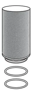
Lubricate the new filter element seals, two per filter element, item 6, with a lubricant suitable for the operating conditions, and fit them to the housing body (1).
Gently push the filter element into the housing body (1).
If multiple filter elements are fitted, assemble and install the filter element support assembly (11) as shown in Figure 2.
Confirm that the housing seal (3) is installed.
Sizes DN8–DN80: Carefully position the housing locking ring (4) on the locating surface of the housing head (2). Then gently lower the housing body (1) over the filter element and tighten the housing locking ring (4). The locking ring has a coarse thread to reduce the risk of seizure. Thread lubricant is normally unnecessary, but may be used if required.
Sizes DN100 and DN150: Gently lower the housing head (2) over the filter element and position it on the housing body (1). Tighten the housing bolts to the recommended torque specified in Table 1.
After completing Steps 1–9, slowly crack open the upstream isolation valve to introduce the process fluid into the CSF16 or CSF16T filter, and then continue with Steps 11–14.
If a whistling sound is heard during gas or steam service, the housing has been assembled incorrectly. Close the upstream isolation valve immediately.
Warning
Before opening the housing, confirm that it has cooled and that any residual pressure inside it has been released.
The housing locking ring (4) or housing bolts (10) may then be loosened. Carefully inspect the housing body and head (1 and 2), the filter element or elements (5, with multiple elements possible on larger sizes), and the housing seal (3), and then reassemble the unit.
If no whistling sound is heard after opening the upstream isolation valve, slowly open the downstream valve until it is fully open. The process fluid will then flow through the CSF16 / CSF16T filter. Record the upstream and downstream pressure gauge readings to check the differential pressure, and record the installation date.
Check all connected pipelines, fittings, and joints for leakage. Exercise particular care in steam service, and include the steam trap in the inspection.
During the first few days after replacing the filter element, isolate the filter and inspect the screen in the filter/line strainer upstream of the filter. Remove any pipeline debris or replace the screen as necessary.
2.3 Stainless Steel Steam Filters
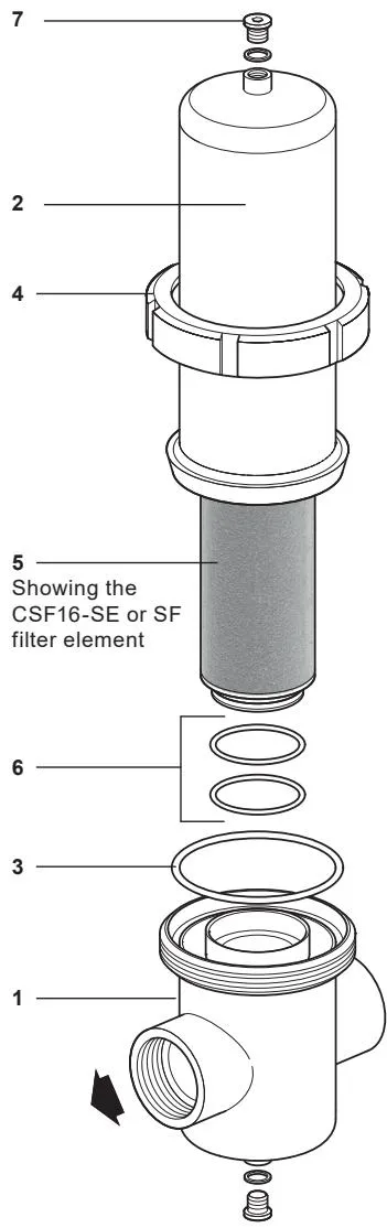
Figure 1 DN8–DN80
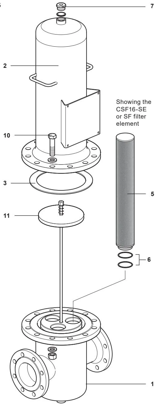
Figure 2 DN100 and DN150L (DN100L shown)
2.4 Stainless Steel Sterile Air Filters