
- Safety Information
- Product Information
- Installation
- Electrical Control Principle and Wiring Diagram
- Operation and Shutdown Maintenance
- Commissioning
- Maintenance and Repair
- Spare Parts
- Troubleshooting
1. Safety Information
Correct installation, commissioning and maintenance by qualified personnel in accordance with the operating instructions is the only guarantee of safe operation of this product (see Section 1.1). After installation, the installation instructions and safety guidelines for the piping system and plant building must be followed, and tools must be used correctly with the necessary safety equipment provided.
1.1 Intended Use
Refer to the installation and maintenance instructions, nameplate and technical information sheet to confirm whether this product is suitable for the application at the intended site. This product is not pressure equipment and is designed for operation at atmospheric pressure. Therefore, the unit is not covered by the European Pressure Equipment Directive.
i) The product is designed for Group 2 fluids under the Pressure Equipment Directive, including steam, air and water/condensate. For use with other fluids, consult Spirax Sarco.
ii) Ensure that the product materials are suitable for the operating conditions, and that the maximum and minimum system pressures and temperatures are within the product’s design range. If the product’s maximum operating range is below the system operating conditions, or if product failure could result in overpressure or overtemperature, install safety devices to address the hazard.
iii) Ensure that the product is installed correctly and that the inlet and outlet are not connected incorrectly.
iv) Spirax Sarco products cannot withstand external pressure. The installer must prevent external forces in the system from acting on this product.
v) Before installing the product in a steam or other high-temperature system, remove the protective covers from all product connections and the protective film from the nameplate.
1.2 Accessibility
After installation, ensure that sufficient operating space is available. Where necessary, provide a safe working platform before operating the product. Provide lifting equipment where required.
1.3 Lighting
Ensure that adequate lighting is available, particularly during detailed or complex operations.
1.4 Hazardous Fluids or Gases in the Pipeline
Consider in advance which fluids are present in the pipeline or may have been present in it. Take care with flammable substances, substances hazardous to health, and substances at high or low temperatures.
1.5 Hazardous Working Environment
Potential hazards include explosion risks, oxygen deficiency, such as inside tanks or in low-lying areas, hazardous gases, high or low temperatures, hot surfaces, fire hazards, such as during welding, excessive noise, and moving machinery.
1.6 The System
Understand how the complete system operates. Before carrying out any operation, such as closing an isolation valve or operating an electrical switch, consider whether this could place other parts of the system or other personnel at risk.
Hazards include isolating drain outlets or protective devices and disabling control or alarm devices. Open and close isolation valves slowly to prevent system shock.
1.7 Pressure Systems
Ensure that system pressure is isolated or completely vented and drained. Consider using double isolation valves and locking or labeling closed valves. Never assume that a pressure gauge reading of zero means that the system has been completely depressurized.
1.8 Temperature
After isolating the product, allow it to cool to room temperature to prevent burns.
1.9 Tools and Spare Parts
Before starting work, ensure that suitable tools and spare parts are available. Use genuine Spirax Sarco spare parts only.
1.10 Protective Clothing
Consider whether operating personnel or personnel in the vicinity require protective clothing.
1.11 Work Permits
All work must be carried out by competent personnel or under their supervision. Installation and operating personnel must be trained in accordance with the product’s installation and maintenance instructions so that they can use the product correctly.
Where a work permit system is in operation, personnel must comply with that system. Where no such system is in operation, the person responsible must understand the nature of the work and, where necessary, appoint a safety assistant.
Post warning notices where necessary.
1.12 Handling
Manual handling of large or heavy products may cause injury. Lifting, pushing, pulling, carrying or supporting heavy loads with the body can cause injury, particularly back injury. It is recommended that the workload, individual capabilities, load and working environment be considered, and that appropriate handling measures be adopted according to site conditions.
1.13 Residual Heat
During normal use, the external surface of this product may become very hot. When operated at the maximum allowable operating temperature, the product surface temperature may reach 200°C (392°F). This product is not self-draining. Take care when removing or moving it from its installed position (refer to the maintenance instructions).
1.14 Freezing
For non-self-draining products used at ambient temperatures below freezing point, appropriate frost protection must be provided.
1.15 Disposal
Unless otherwise stated in the installation and maintenance instructions, this product is recyclable and presents no ecological hazard when disposed of properly.
1.16 Returning Products
In accordance with EC health, safety and environmental legislation, when returning products, customers and resellers must provide hazard information and carefully handle any residual contaminants or mechanical damage that may present a health, safety or environmental hazard. Hazard information must be submitted in writing, including health and safety data sheets identifying any known or potential hazards.
2. Product Information
2.1 Introduction
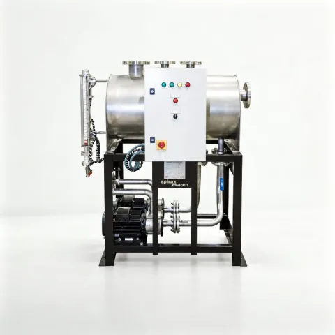
The Spirax Sarco open electric condensate recovery pump set uses electric power to pressurize and recover high-temperature steam condensate for use in processes or as boiler make-up water. The unit mainly comprises a control system, condensate tank, electric centrifugal pump and other piping accessories.
The unit is installed and tested before shipment. It can be put into operation after the site connections for water and electricity have been completed.
2.2 Main Components
Control System
A touchscreen and PLC control system are used to meet condensate management requirements. The system incorporates a magnetic flap level gauge and temperature detection device, with level and temperature signal outputs available. The electric pump level settings can be configured flexibly according to the actual load conditions at the site. The complete unit is controlled by a programmed system and can operate automatically without attendance after commissioning has been completed.
Electric Pump
The unit uses a Grundfos high-temperature electric pump with an integrated motor, mechanical seal, Class F insulation and IP55 protection rating. The standard configuration includes an automatic air venting device to prevent mechanical seal or motor damage caused by the ingress of air or steam.
Condensate Tank
The tank and associated connecting pipework are made of carbon steel. Standard products have a blue-painted surface. Stainless steel construction is also available; consult Spirax Sarco for details. An anti-vortex device is installed inside the tank, and a sufficient inlet head is ensured. A magnetic flap level gauge is fitted as standard on the side of the tank. The tank is designed with a drain outlet, overflow outlet and condensate inlet.
2.3 Technical Data Requirements
| Maximum design water temperature | 95°C |
| Power supply requirements | 380V, three-phase, 50Hz |
| Control | Level control provided by PLC |
2.4 Selection Guidelines
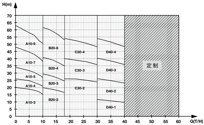
According to the selection table above, draw a horizontal line from the pump head and a vertical line from the condensate flow rate to be handled. The pump model to be selected is identified by the intersection of the two lines. If there are any special requirements, specify them when placing the order.
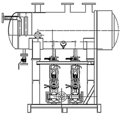
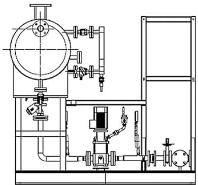
2.5 Connection Port Sizes and Dimensions
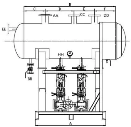
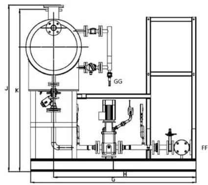
Connection Port Sizes
| Model | AA | BB | CC | DD | EE | FF | GG | HH | Anchor Foot |
| A10 | DN100 | DN25 | DN80 | DN100 | DN50 | DN50 | DN15 | DN40 | φ 22 |
| B20 | DN150 | DN25 | DN100 | DN150 | DN80 | DN65 | DN15 | DN65 | φ 22 |
| C30 | DN150 | DN25 | DN100 | DN150 | DN80 | DN80 | DN15 | DN80 | φ 22 |
| D40 | DN150 | DN25 | DN150 | DN200 | DN80 | DN100 | DN15 | DN80 | φ 22 |
Dimensions (approx. mm)
| Model | A | B | C | D | E | F | G | H | L | J | K | Weight (kg) |
| A10 | 1230 | 1600 | 370 | 500 | 360 | 370 | 1825 | 1569 | 600 | 1835 | 1835 | 1000 |
| B20 | 1350 | 1800 | 435 | 500 | 430 | 435 | 2000 | 1643 | 900 | 2392 | 2342 | 1400 |
| C30 | 1350 | 1800 | 435 | 500 | 430 | 435 | 2150 | 1795 | 900 | 2402 | 2352 | 1500 |
| D40 | 1450 | 1800 | 280 | 650 | 590 | 280 | 2330 | 1910 | 1200 | 2802 | 2752 | 1800 |
Note: The weight is an approximate value excluding water.
Electric Pump Power and Cable Specification Table
| Model | Mode: Single-Motor Power (kW) | Electric Pump Group Power (kW) | Power Cable Specification (mm²) |
| A10-3 | 0.55 | 1.3 | 4*2.5+1*1.5 |
| A10-4 | 0.55 | 1.3 | 4*2.5+1*1.5 |
| A10-5 | 0.75 | 1.7 | 4*2.5+1*1.5 |
| A10-7 | 1.1 | 2.5 | 4*2.5+1*1.5 |
| A10-9 | 1.5 | 3.3 | 4*2.5+1*1.5 |
| B20-2 | 0.75 | 1.7 | 4*2.5+1*1.5 |
| B20-3 | 1.1 | 2.5 | 4*2.5+1*1.5 |
| B20-4 | 1.5 | 3.3 | 4*2.5+1*1.5 |
| B20-6 | 2.2 | 4.7 | 4*2.5+1*1.5 |
| C30-2 | 2.2 | 4.7 | 4*2.5+1*1.5 |
| C30-3 | 3 | 6.3 | 4*4.0+1*2.5 |
| C30-4 | 4 | 8.3 | 4*4.0+1*2.5 |
| D40-1 | 1.1 | 2.5 | 4*2.5+1*1.5 |
| D40-2 | 2.2 | 4.7 | 4*2.5+1*1.5 |
| D40-3 | 4 | 8.3 | 4*4.0+1*2.5 |
| D40-4 | 5.5 | 11.3 | 4*6.0+1*4 |
3. Installation
Note: Read the safety information in Chapter 1 carefully before installation.
3.1 The pump group is packed in a wooden crate. Check it upon receipt to ensure that it has not been damaged. The pump group includes 1 control cabinet, 2 electric pumps, a magnetic flap level gauge, a signal transmitter, a pressure gauge, and other components.
3.2 The two electric pumps are installed below the water tank. Isolation valves are provided at the inlets and outlets, and check valves are provided at the outlets.
3.3 Check the material, pressure range, and temperature range of the pump group. Ensure that the maximum operating pressure and temperature range of the pump group are higher than the system pressure and temperature range to ensure safety.
3.4 Remove the protective covers from all connections.
3.5 Ensure correct installation and flow direction.
3.6 Piping: The piping connected to the condensate collection tank and the electric pump outlets must not be subjected to stresses caused by expansion or inadequate support.
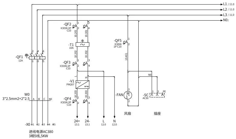
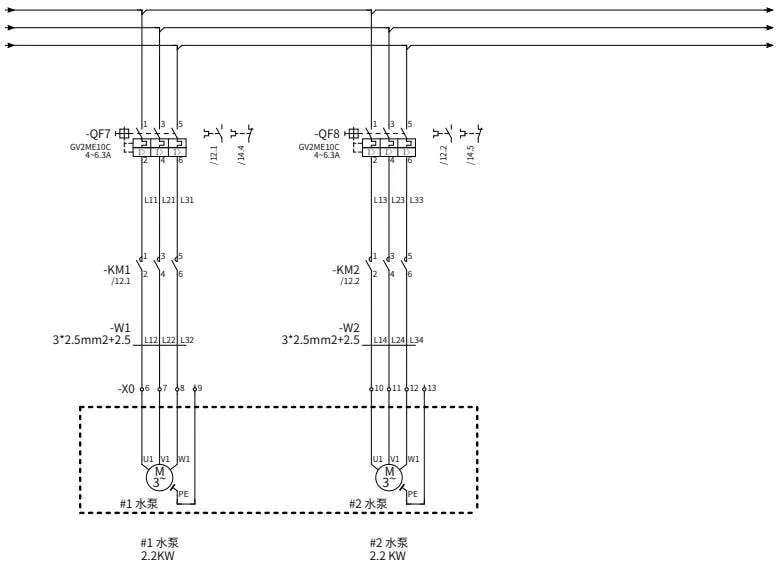
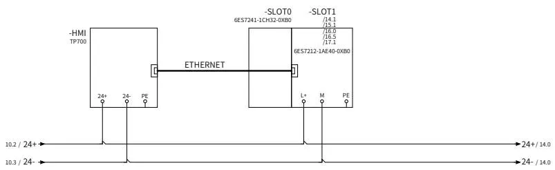
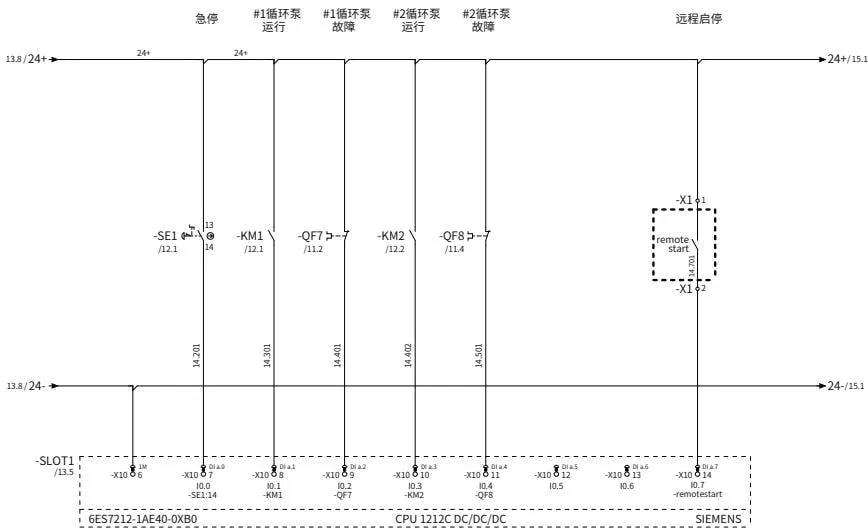
3.7 Electrical wiring: Refer to the electrical control schematic for wiring, including the power and signal cables. All electrical wiring must comply with national or local code requirements.
3.8 The condensate collection tank is not a pressure vessel and must not be pressurized. It must be vented to the atmosphere.
4. Electrical Control Principles and Wiring Diagrams
4.1 Incoming Power Circuit
4.2 Pump Main Circuit
4.3 Control Circuit
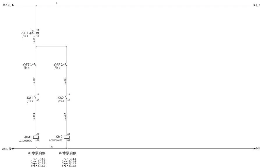
4.4 System Diagram
4.5 DI
4.6 DO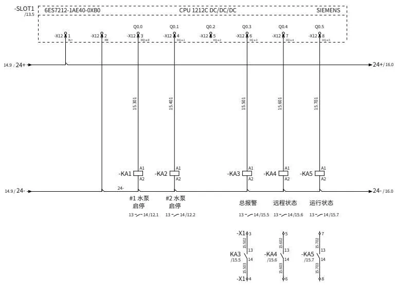
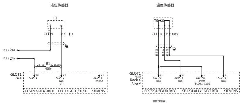
4.7 AI
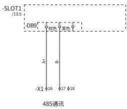
4.8 Modbus
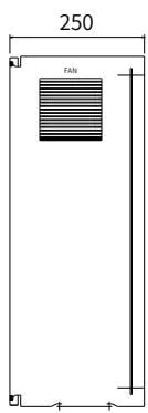
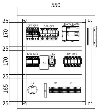
4.9 Layout Drawing
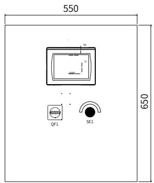
4.10 Terminal Diagram Table
| Function | Terminal | Wire No. | Page/Path ^WER | Terminal Model |
| =+-X0 | ||||
| Incoming power: AC 380 V, 3-phase, 5-wire, 5 kW | 1 • | A | /10.1 | GK5 |
| = | 2 • | B | /10.1 | GK5 |
| = | 3 • | C | /10.1 | GK5 |
| = | 4 • | N0 | /10.1 | GK5 |
| = | 5 • | /10.2 | GK5PE | |
| #1 Pump, 2.2 kW | 6 • | L12 | /11.2 | GK5 |
| = | 7 • | L22 | /11.2 | GK5 |
| = | 8 • | L32 | /11.2 | GK5 |
| = | 9 • | /11.2 | GK5PE | |
| #2 Pump, 2.2 kW | 10 • | L14 | /11.4 | GK5 |
| = | 11 • | L24 | /11.5 | GK5 |
| = | 12 • | L34 | /11.5 | GK5 |
| = | 13 • | /11.5 | GK5PE | |
| =+-X1 | ||||
| Remote start/stop | 1 • | 24+ | /14.7 | GK3 |
| Remote start/stop | 2 • | 14.701 | /14.7 | GK3 |
| Total alarm | 3 • | 15.502 | /15.5 | GK3 |
| = | 4 • | 15.503 | /15.5 | GK3 |
| Remote status | 5 • | 15.602 | /15.6 | GK3 |
| = | 6 • | 15.603 | /15.6 | GK3 |
| Operating status | 7 • | 15.702 | /15.7 | GK3 |
| = | 8 • | 15.703 | /15.7 | GK3 |
| Level sensor | 9 • | 24+ | /16.1 | GK3 |
| = | 10 • | 16.101 | /16.2 | GK3 |
| = | 11 • | /16.2 | GK3PE | |
| Temperature sensor | 12 • | 16.501 | /16.5 | GK3 |
| = | 13 • | 16.502 | /16.5 | GK3 |
| = | 14 • | 16.601 | /16.6 | GK3 |
| = | 15 • | /16.6 | GK3PE | |
| RS-485 communication | 16 • | A+ | /17.1 | GK3 |
| = | 17 • | B- | /17.2 | GK3 |
| = | 18 • | /17.2 | GK3PE | |
| 19 • | GK3 | |||
| 20 • | GK3 | |||
| 21 • | GK3 | |||
| 22 • | GK3 | |||
| 23 • | GK3 | |||
| 24 • | GK3 | |||
| 25 • | GK3 | |||
5. Operation
After installation or maintenance, ensure that the system is connected correctly.
5.1 Startup
- Check whether the system pressure piping and accessory connections are normal.
- Ensure that all system isolation valves remain fully open, and confirm that the system can be filled with water normally.
- Check whether the electrical system is functioning normally.
- Before energizing the equipment, check whether the electric pump is filled with water through the air vent valve on the pump.
- Energize the control cabinet only after confirming that the cabinet grounding and power supply are reliable.
- After energization, first check whether the instruments display correctly.
- Check whether all touch-screen pages are displayed correctly.
5.2.1 Storage Protection
The pump assembly undergoes a hydrostatic pressure test before shipment, so residual water may remain in the piping and pump casing when the equipment is shipped. If the equipment is not installed and operated after delivery, take measures to prevent freezing. Similarly, water may remain in the piping and pump casing after system shutdown, so appropriate freeze protection measures must be taken.
5.2.2 Equipment Shutdown
- Stop the electric pump manually.
- Switch off the power supply.
- Close the electric pump inlet and outlet valves.
- Drain the water from the system through the drain valve on the tank, and discharge the condensate to a safe area.
- If the water pump will remain shut down for an extended period, take measures to prevent freezing.
6. Commissioning
6.1 Control Cabinet Display Operation Instructions
Main Screen
The main screen is the main window of the electric pump control system. It controls the water pumps and displays measurement parameters such as level, temperature, flow rate, and heat.
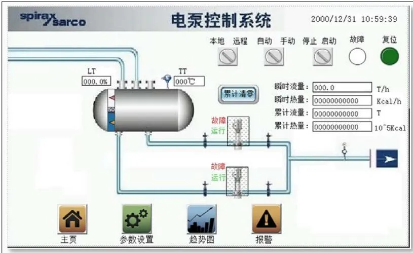
Pump Assembly Control
The water pumps have three control modes: local-automatic control, local-manual control, and remote control. The operating steps are as follows:
▶ Local-Automatic Control (Recommended Primary Operating Mode)
- Step 1: Set the selector switch to local and automatic.
Local Remote Automatic Manual


- Step 2: After switching the system stop/start selector to Start, automatic operation begins. After switching it to Stop, the system stops.
Stop Start

▶ Local Manual Control
- Step 1: Set the selector switch to Local, Manual, or Stop.
Local
Remote
Auto
Manual
Stop
Start


- Step 2: Click the graphic for Pump 1 or Pump 2 to open the corresponding control dialog, then click the Start/Stop button to control the corresponding pump.
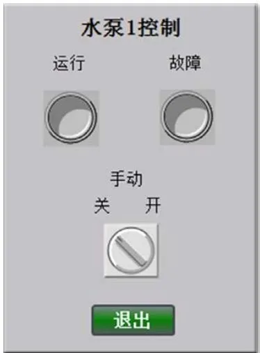
▶ Remote Control
If the customer has a supervisory computer, set the selector switch to Remote to enable start/stop control from the supervisory computer.
▶ Reset Cumulative Total
Click
Reset Cumulative Total
to reset the current cumulative value to zero and start accumulating again.
Parameter Settings
The parameter settings screen allows you to set the pump control level, alarm level, pump discharge pressure input, and pump changeover time.
Note: The pump discharge pressure input is used to calculate flow rate and heat quantity.
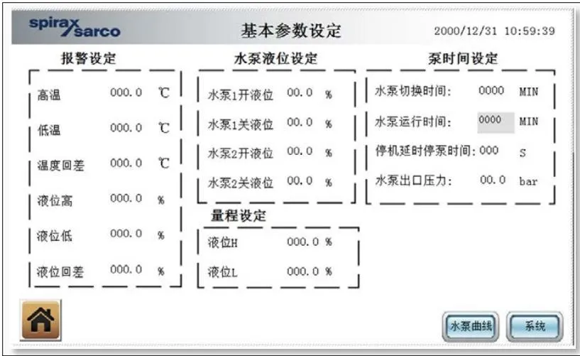
Trend Charts
The trend chart screen displays current and historical level or temperature trends.
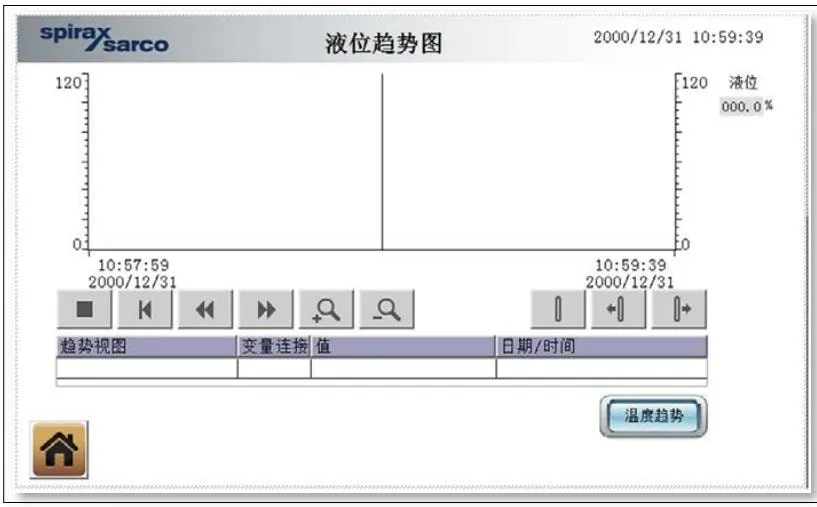
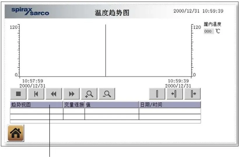
The table below the trend chart displays the corresponding historical data.
| Trend View | Variable Connection | Value | Date/Time |
▶ Toolbar Functions
- Select the time point for viewing the control curve:

- Zoom in or out of the trend chart:
- Move the reference line left or right:
Alarms
Click “Alarms” on the main screen to open the alarm screen, which displays the generated alarm records.
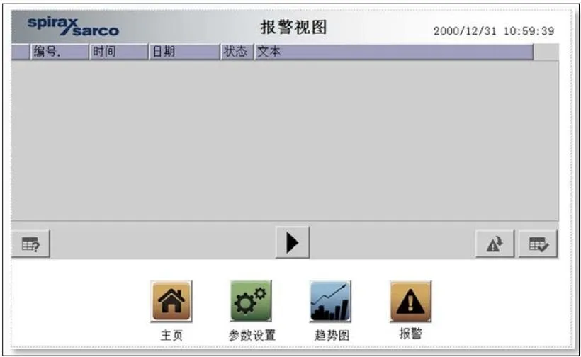
Alarm List
| No. | Alarm Description | Remarks |
| 1 | Low Level Alarm | Check the actual level and whether the make-up water valve is opening correctly |
| 2 | High Level Alarm | Check the actual level and whether the make-up water valve is closing correctly |
| 3 | Pump 1 Fault | Pump 1 overcurrent; check the pump and measure the actual current |
| 4 | Pump 2 Fault | Pump 2 overcurrent; check the pump and measure the actual current |
| 5 | High Temperature Alarm | Check the actual temperature and whether the temperature control valve is regulating correctly |
| 6 | Low Temperature Alarm | Check the actual temperature and whether the temperature control valve is regulating correctly |
| 7 | Emergency Stop Alarm | The emergency stop button has been pressed. Release it by turning it, then press the reset button |
7. Maintenance and Repair

Note: Before starting any repair work, refer to the safety information in Part 1.
Power Isolation
Isolate the pump inlet and ensure that the tank does not leak. Allow the condensate to cool sufficiently (below 25°C), then slowly open the pump outlet to discharge the condensate to a safe area.
If only one pump is being repaired or maintained while the system remains in normal operation, operate the control cabinet as follows: switch to single-pump operation; after ensuring that it is safe to do so, isolate the inlet and outlet isolation valves of the pump requiring repair, allow it to cool to a safe temperature, and do not begin repair or maintenance until the condensate has been completely drained. After the repair or maintenance is complete, perform a thorough inspection. Only after confirming that the pump has been installed correctly may you operate the control cabinet and switch to dual-pump operation.
If the pump requires repair or servicing, refer to the pump manufacturer’s operating instructions. Contact Spirax Sarco to order spare parts if required.
Periodic inspection and maintenance are effective ways to ensure efficient operation of the pump set.
8. Spare Parts
For spare parts, contact Spirax Sarco promptly.
9. Troubleshooting
| Fault | Possible Cause | Action |
| Insufficient Capacity | 1. Incorrect direction of rotation | Viewed from the pump toward the motor, the rotation should be counterclockwise. If not, rewire the motor |
| 2. Inlet valve partially open | Ensure that the valve is fully open | |
| 3. Discharge valve partially open | Adjust the valve opening according to the capacity requirements to avoid cavitation | |
| 4. Condensate temperature too high | Confirm the system design temperature | |
| 5. Pressure loss in the condensate return piping exceeds the design value | Ensure that the system flow loss and static head do not exceed the pump head | |
| Cavitation | 1. Inlet valve partially open | Ensure that the valve is fully open |
| 2. Insufficient head | Increase the pump discharge valve opening to increase the head | |
| 3. Condensate temperature too high | Confirm the condensate temperature | |
| 4. Impeller partially blocked | Remove the pump and clean the impeller | |
| Frequent Starting | 1. Improper level setting | Reset the level |
| 2. Level gauge damaged | Inspect and replace the level gauge | |
| Excessive Capacity | 1. Head too low | Partially close the pump discharge shut-off valve to increase resistance. Do not close the valve completely |
| 2. Incorrect motor wiring | Check the wiring against the electrical diagram | |
| 3. Incorrect rotation | Viewed from the pump toward the motor, ensure that the rotation is counterclockwise | |
| 4. Mechanical friction | Check whether the pump is blocked internally |
Note: For faults related to the electric pump, refer to the electric pump documentation