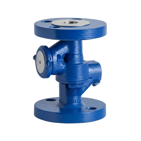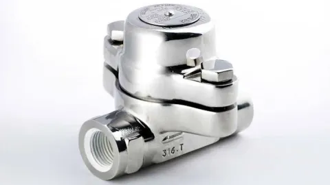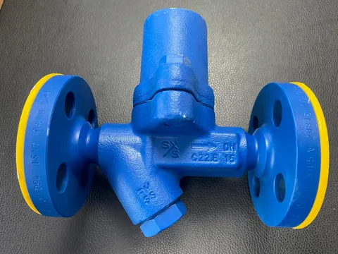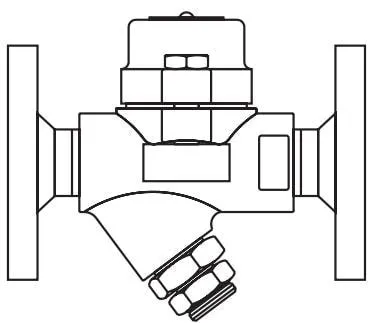
IBPC32 IBPS32
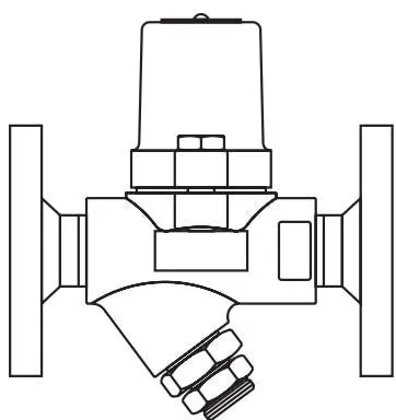
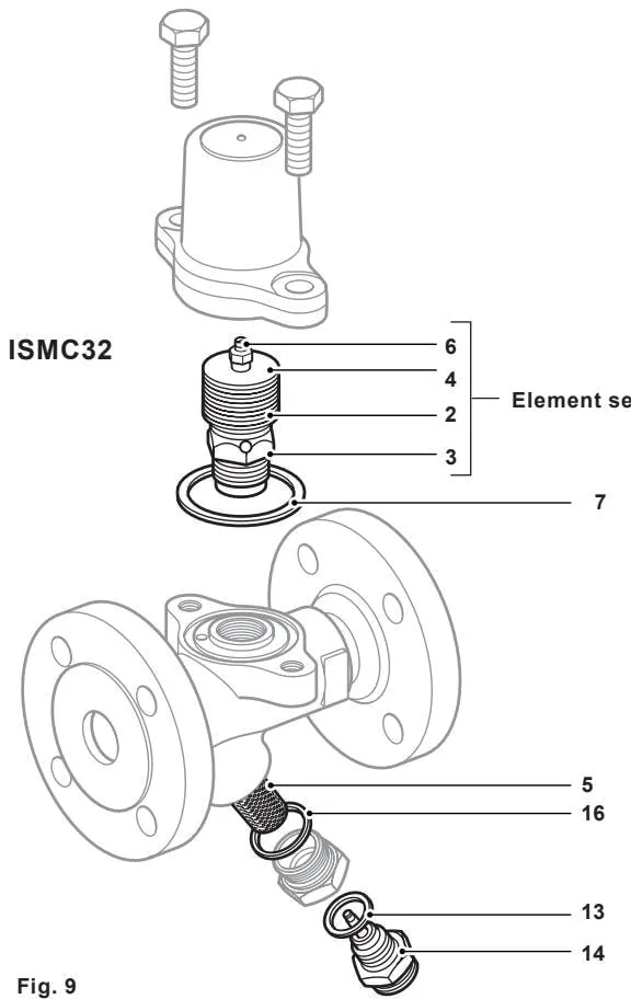
ISMC32
Safety information
Product information
Installation
Commissioning
Operation
Maintenance
Spare parts
1. Safety information
Safe operation of these products can only be guaranteed if they are properly installed, commissioned, used and maintained by qualified personnel (see Section 1.11) in accordance with the operating instructions. General installation and safety instructions for pipeline and plant construction, together with the correct use of tools and safety equipment, must also be complied with.
1.1 Intended use
Refer to the Installation and Maintenance Instructions, name-plate and Technical Information Sheet to check that the product is suitable for the intended use/application.
The products listed below comply with the requirements of the European Pressure Equipment Directive 2014/68/EU and carry the mark where required.
These products fall within the following categories of the Pressure Equipment Directive:
| Product | Group 2 gases | Group 2 liquids |
| IBPC32, IBPS32 and ISMC32 | SEP | SEP |
i) These products have been specifically designed for use with steam, air or water/condensate, which are in Group 2 of the Pressure Equipment Directive mentioned above. The products’ use with other fluids may be possible, but if this is contemplated, Spirax Sarco should be contacted to confirm the suitability of the product for the application being considered.
ii) Check the suitability of the materials, pressure and temperature and their maximum and minimum values. If the maximum operating limits of the product are lower than those of the system in which it is being installed, or if product malfunction could result in a dangerous overpressure or overtemperature, ensure that a safety device is included in the system to prevent such limit conditions.
iii) Determine the correct installation position and the direction of fluid flow.
iv) Spirax Sarco products are not intended to withstand external stresses that may be induced by the system into which they are installed. It is the installer’s responsibility to consider these stresses and take adequate precautions to minimise them.
v) Remove protective covers from all connections before installation.
1.2 Accessibility
Ensure safe access and, if necessary, provide a safe working platform with suitable protection. Arrange suitable lifting equipment where required.
1.3 Lighting
Ensure adequate lighting, particularly where detailed or complex work is required.
1.4 Hazardous liquids or gases in the pipeline
Consider what is in the pipeline or what may have been in the pipeline previously. Consider: flammable materials, substances hazardous to health, extreme temperatures.
1.5 Hazardous environment around the product
Consider: explosion risk areas, lack of oxygen (for example, tanks and pits), dangerous gases, extreme temperatures, hot surfaces, fire hazards (for example, during welding), excessive noise and moving machinery.
1.6 The system
Consider the effect of the proposed work on the entire system. Could any proposed action (for example, closing isolation valves or electrical isolation) put any other part of the system or any personnel at risk?
Dangers may include isolating vents or protective devices, or making controls or alarms ineffective. Ensure that isolation valves are opened and closed gradually to avoid system shock.
1.7 Pressure systems
Ensure that any pressure is isolated and safely vented to atmospheric pressure. Consider double isolation (double block and bleed) and locking or labelling closed valves. Do not assume that the system has depressurised just because the pressure gauge reads zero.
1.8 Temperature
Allow time for the temperature to normalise after isolation to avoid the danger of burns.
1.9 Tools and consumables
Before starting work, ensure that suitable tools and/or consumables are available. Use genuine Spirax Sarco replacement parts only.
1.10 Protective clothing
Consider whether you and/or others in the vicinity require protective clothing to protect against, for example, chemicals, high or low temperatures, radiation, noise, falling objects, and hazards to the eyes and face.
1.11 Permits to work
All work must be carried out by, or under the supervision of, a suitably competent person. Installation and operating personnel should be trained in the correct use of the product in accordance with the Installation and Maintenance Instructions.
Where a formal “permit to work” system is in force, it must be complied with. Where there is no such system, it is recommended that a responsible person knows what work is being carried out and, where necessary, arranges for an assistant whose primary responsibility is safety.
1.12 Handling
Manual handling of large and/or heavy products may present a risk of injury. Lifting, pushing, pulling, carrying or supporting loads by bodily force can cause injury, particularly to the back. You are advised to assess the risks, taking into account the task, the individual, the load and the working environment, and use appropriate handling methods according to the circumstances of the work being performed.
1.13 Residual hazards
During normal use, the external surface of the product may be very hot. If used at the maximum permitted operating conditions, the surface temperature of some products may exceed 500 °C (932 °F).
Many products are not self-draining. Take particular care when dismantling or removing the product from an installation (refer to the Maintenance Instructions).
1.14 Freezing
Provision must be made to protect products that are not self-draining and are exposed to environments below freezing point.
1.15 Safety information
For specific details relating to these products, refer to the relevant sections of the accompanying Installation and Maintenance Instructions.
1.16 Disposal
Unless otherwise stated in the Installation and Maintenance Instructions, this product is recyclable and its disposal does not present an ecological hazard, provided that it is disposed of carefully.
Where additional information is not provided on the Spirax Sarco product compliance web pages, this product can be safely recycled and/or disposed of, provided that it is handled with care. Always comply with local recycling and disposal regulations.
1.17 Returning products
Customers and stockists are reminded that, under EC health, safety and environmental laws, when returning products to Spirax Sarco they must provide information about any hazards and the precautions to be taken due to contamination residues or mechanical damage that may present a health, safety or environmental risk. This information must be provided in writing, including health and safety data sheets relating to any substances identified as hazardous or potentially hazardous.
2. Product information
2.1 Description
The IBPC32, IBPS32 and ISMC32 series of steam traps with integral sensors are designed for direct installation into steam lines without the need for an additional sensor chamber.
They are available with an integral sensor for detecting waterlogging and steam leakage (WLS1), or for detecting steam leakage only (SS1). All trap types can be easily integrated into an existing Spiratec monitoring system. When connecting to an R1C (IM-P087-33) or R16C (IM-P087-21 and IM-P087-22) automatic monitoring unit, refer to the relevant Installation and Maintenance Instructions.
All pressure-containing parts are manufactured by TÜV-approved suppliers in accordance with AD-Merkblatt WO/TRD100.
These steam traps are unaffected by waterhammer and are available in the following models:-
| IBPC32 | Carbon steel balanced pressure thermostatic steam trap with integral Spiratec sensor. |
| IBPC32CV | Carbon steel balanced pressure thermostatic steam trap with check valve and integral Spiratec sensor. |
| IBPS32 | Stainless steel balanced pressure thermostatic steam trap with integral Spiratec sensor. |
| IBPS32CV | Stainless steel balanced pressure thermostatic steam trap with check valve and integral Spiratec sensor. |
| ISMC32 | Carbon steel bimetallic steam trap with integral Spiratec sensor. |
Note: When ordering IBPC32, IBPC32CV, IBPS32 or IBPS32CV, the type of capsule fill must be specified.
Capsule fill and operation:
Standard capsule - marked “STD”, operates at approximately 12 °C (21.6 °F) below steam saturation temperature.
Optional - capsules are available for subcooled “SUB” operation at approximately 24 °C (43.2 °F) below steam saturation temperature, or near-saturated “NTS” operation at approximately 6 °C (10.8 °F) below steam temperature.
Standards
These products fully comply with the requirements of the European Pressure Equipment Directive 2014/68/EU.
Certification
These products are available with EN 10204 3.1 certification.
Note: All certification/inspection requirements must be specified at the time of ordering.
Note: For further information, refer to the following Technical Information Sheets:
IBPC32 and IBPC32CV TI-P005-06, IBPS32 and IBPS32CV TI-P005-05, ISMC32 TI-P076-11
2.2 Sizes and pipe connections
1/2”, 3/4” and 1” threaded connections BSP T Rp (ISO 7-1) or NPT.
1/2”, 3/4” and 1” socket weld ends to BS 3799.
1/2”, 3/4” and 1” butt weld ends to EN 12 627.
DN15, DN20 and DN25 standard flanges to EN 1092 PN40, ANSI B 16.5 Class 150 and 300, JIS/KS 10K and JIS/KS 20K.
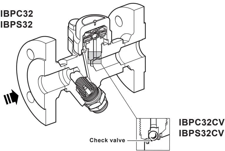
Figure 1
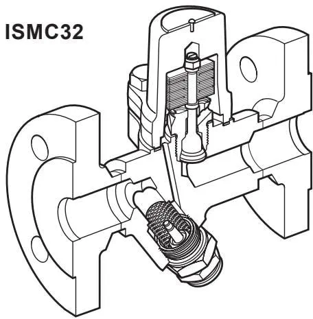
Figure 2
2.3 Pressure/temperature limits
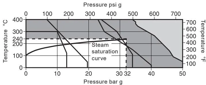
IBPC32, IBPC32CV and ISMC32
IBPS32 and IBPS32CV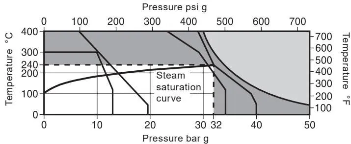
This product must not be used in this area.
This product should not be used in this area or beyond its operating range, otherwise internal components may be damaged.
A - B Threaded, socket weld, butt weld and ANSI 300 flanged.
A - C EN 1092 PN40 flanged.
A - D JIS/KS 20K flanged.
A - E ANSI 150 flanged.
F - G JIS/KS 10K flanged.
| Body design conditions | PN40 | |||
| PMA | Maximum allowable pressure | 50 bar g @ 50 °C | (725 psi g @ 122 °F) | |
| TMA | Maximum allowable temperature | IBPC32, IBPC32CV and ISMC32 | 400 °C @ 35 bar g | (752 °F @ 507 psi g) |
| IBPS32 and IBPS32CV | 400 °C @ 30 bar g | (752 °F @ 435 psi g) | ||
| Minimum allowable temperature | IBPC32, IBPC32CV, ISMC32 | -60 °C | (-76 °F) | |
| IBPS32, IBPS32CV | -200 °C | (-328 °F) | ||
| PMO | Maximum operating pressure for saturated steam service | 32 bar g | (464 psi g) | |
| TMO | Maximum operating temperature | 240 °C @ 32 bar g | (464 °F @ 464 psi g) | |
| Minimum operating temperature. Note: Contact Spirax Sarco for lower operating temperatures. | 0 °C | (32 °F) | ||
| Designed for a maximum cold hydraulic test pressure of: | 75 bar g | (1088 psi g) | ||
3. Installation
Note: Before carrying out any installation, observe Section 1, “Safety information”.
Refer to the installation and maintenance instructions, name-plate and technical information sheet to check that the product is suitable for the intended installation:
3.1 Check the materials, pressure and temperature and their maximum values. If the product’s maximum operating limits are lower than those of the system in which it is installed, ensure that a safety device is included in the system to prevent overpressure.
3.2 Determine the correct installation position and the direction of fluid flow.
3.3 Remove protective covers from all connections.
3.4 These steam traps must be installed in horizontal pipework, preferably with a drop leg immediately upstream of the steam trap, typically 150 mm (6”), see Figure 3. Note: If a drop leg cannot be installed, steam may flow through the condensate at the bottom of the pipework and reach the steam trap under low-load conditions.
3.5 For steam traps discharging condensate into a return line with backpressure, always install a check valve downstream of the steam trap. This is typically caused by a rising condensate line. The check valve prevents the steam space from flooding when the inlet pressure falls or the steam is shut off. Use a suitable valve, such as Spirax Sarco DCV41, see Figure 3.
3.6 When the steam trap discharges to atmosphere, a diffuser is strongly recommended on the steam trap outlet. This can reduce noise and erosion problems by buffering the high-velocity discharge. For further information, see TI-P155-02.
3.7 Isolation valves must be installed to allow safe maintenance and replacement of the steam trap.
Open the isolation valve slowly until normal operating conditions are reached.
3.9 Check for leaks and correct operation.
3.10 Ensure sufficient space is available to remove the cover from the body for maintenance. The minimum withdrawal distance for the covers of IBPC32, IBPC32CV, IBPS32 and IBPS32CV is 37 mm (1½”), for ISMC32 it is 51 mm (2”), and the minimum withdrawal distance for the strainer and sensor is 28 mm (11/8”).
3.11 Welding into the pipework - provided the arc welding method is used, it is not necessary to remove the operating capsule or element from the product. For specific welding procedures, refer to the relevant national and international welding standards.
Note: If the steam trap discharges to atmosphere, ensure that it discharges to a safe location, as the discharged fluid may reach temperatures of up to 100 °C (212 °F).
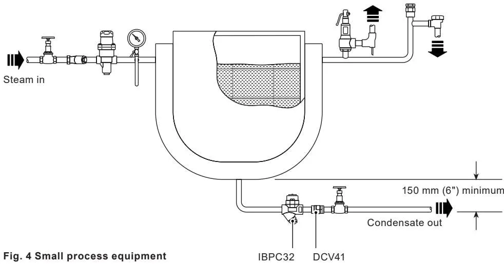
Figure 3 Small process equipment
4. Commissioning
Note: The steam trap is supplied with a blanking plug fitted in the sensor connection. It is recommended that the steam trap be operated under normal conditions for 24 hours before removing the blanking plug.
This allows any pipe debris to be cleared from the strainer before the sensor is installed. Failure to complete this commissioning procedure may affect sensor operation. Before installing the sensor, the steam trap must be isolated from the steam supply and condensate return lines, and any pressure must be safely released to atmospheric pressure. Allow the steam trap to cool. Remove the blanking plug from the connection, ensure that the steam trap is securely supported, and then fit the sensor. Ensure that the gasket is centred when screwing the sensor into the connection. Tighten to the recommended tightening torque (see Table 1). If a waterlogging sensor is to be installed, it is necessary to follow the installation procedure in IM-P087-34 supplied with the sensor.
After installation or maintenance, ensure that the system is fully operational. Test any alarm or protective devices.
5. Operation
5.1 IBPC32, IBPC32CV, IBPS32 and IBPS32CV
The operating element is a capsule containing a small quantity of a special liquid with a boiling point lower than that of water. Under cold conditions at start-up, the capsule is relaxed. The valve lifts off its seat and opens fully, allowing air to be discharged without obstruction. This is a feature of all balanced pressure steam traps and explains why they are particularly suitable for air venting.
As condensate passes through the balanced pressure steam trap, heat is transferred to the liquid in the capsule. The filling liquid boils before steam reaches the steam trap. The vapour pressure inside the capsule causes it to expand, closing the steam trap. The subsequent heat loss from the steam trap cools the water surrounding the capsule, causing the filling liquid to condense. The capsule contracts and opens the valve to release condensate, repeating the cycle until the steam temperature is approached again.
These steam traps are fitted with an integral sensor for detecting waterlogging and water vapour leakage (WLS1), or steam leakage only (SS1).
5.2 ISMC32
The ISMC32 bimetallic steam trap operates using two opposing forces acting on the valve: the opening force generated by system pressure and the closing force generated by condensate temperature acting on the bimetallic element. The ISMC32 operates without steam loss and automatically provides rapid discharge of air, non-condensable gases and large quantities of cold water during start-up.
This steam trap is fitted with an integral sensor for detecting waterlogging and water vapour leakage (WLS1), or steam leakage only (SS1).
6. Maintenance
Note: Before carrying out any maintenance procedure, observe Section 1, “Safety information”.
Warning
The cover gasket contains a very thin stainless steel support ring, which may cause physical injury if it is handled or disposed of incorrectly.
6.1 General information
Before carrying out any maintenance on the steam trap, it must be isolated from the steam supply and condensate return lines, and any pressure must be safely released to atmospheric pressure. Allow the steam trap to cool. When reassembling, ensure that all mating surfaces are clean.
Subject to compliance with the appropriate safety procedures, maintenance can be carried out while the steam trap remains in the pipeline. New gaskets and spare parts are recommended whenever maintenance is performed. Always ensure that the correct tools and necessary protective equipment are used. After maintenance is complete, open the isolation valve slowly and check for leaks.
Note: The sensor should be removed periodically for inspection and cleaning of the insulation, as an accumulation of pipeline residue may affect sensor function. The inspection frequency will depend on the condensate quality. If pitting is present in the insulation, the sensor should be replaced.
More detailed service information is provided in the following sections:
| IBPC32, IBPC32CV, IBPS32 and IBPS32CV | See Sections 6.2, 6.4 and 6.5 |
| ISMC32 | See Sections 6.3, 6.4 and 6.5 |
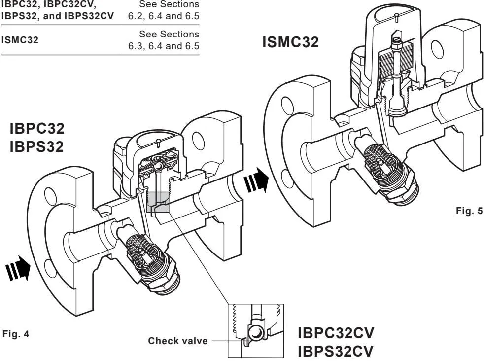
6.2 How to fit a new capsule and valve seat - IBPC32, IBPC32CV, IBPS32 and IBPS32CV
\- Unscrew the two cover bolts (9) and remove the cover (1) and spring (17) from the body (8).
\- Remove the capsule (2) and support plate (18).
\- Unscrew the valve seat (3) from the body (8).
\- Replace the valve seat (3) and tighten to the recommended torque (see Table 1).
It is recommended that a new cover gasket (7) be fitted. Reassemble the support plate (18), ensuring that it is centred on the valve seat (3).
\- Reassemble the capsule (2), spring (17) and cover (1).
Note: Ensure that the cover bolts (9) are tightened progressively to the recommended torque (see Table 1).
6.3 How to install a new element set - ISMC32
Warning: Do not disassemble the element set by removing the lock-nut (4), as this will affect the trap setting.
- Unscrew the two cover bolts (9) and remove the cover (1) from the body (8).
- Unscrew the seat (3) and remove the complete element set.
- Replace the element set and tighten the seat (3) to the recommended torque (see Table 1).
- It is recommended that a new cover gasket (7) is fitted before replacing the cover (1).
Note: Ensure that the cover bolts (9) are tightened progressively to the recommended torque (see Table 1).
Table 1 Recommended tightening torques
| Item | Part | Spanner size | or mm | N m | (lbf ft) |
| 3 | Seat | 24 A/F | 115 - 125 | (82 - 89) | |
| 9 | Cover bolts | 16 A/F | M10 x 30 | 23 - 27 | (16 - 19) |
| 12 | Sensor connector | 27 A/F | 120 - 135 | (88 - 99) | |
| 14 | Sensor | 24 A/F | 50 - 56 | (36 - 40) |
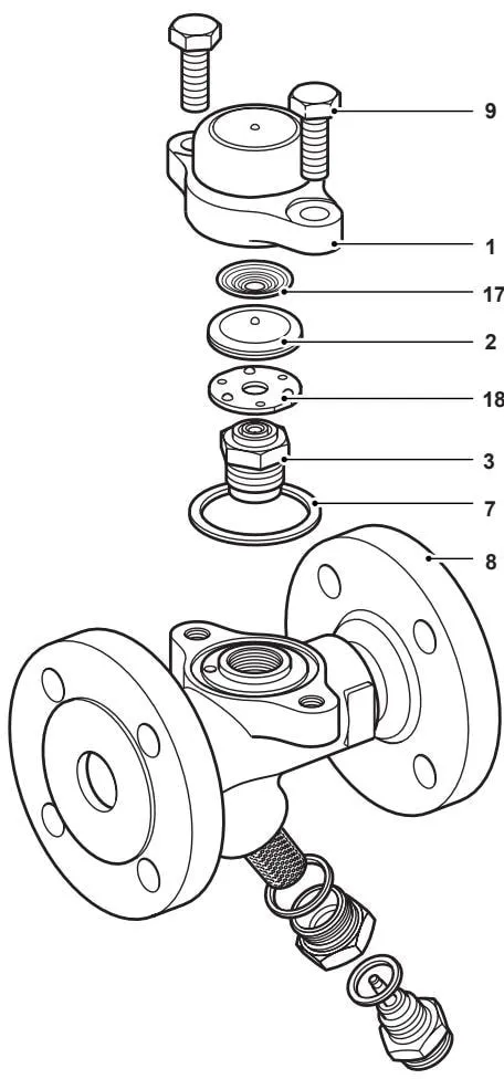
Fig. 6a
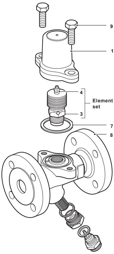
Fig. 7a
6.4 How to replace or clean the Y-type strainer
Note: If a waterlogging sensor is fitted, it is necessary to disconnect the wiring at the electrical terminals.
Unscrew and remove the sensor connector (12). Note: The sensor (14) does not need to be removed from the connector.
- Clean or replace the strainer screen (5) as necessary.
Refit the strainer screen (5) and sensor assembly, ensuring that the screen is centrally positioned, and fit a new gasket (16), ensuring that the mating surfaces are clean. Apply a small amount of molybdenum disulphide grease to the first few threads.
- Tighten the sensor connector (12) to the recommended tightening torque (see Table 1).
- Reconnect the waterlogging sensor in accordance with the instructions in IM-P087-34.
6.5 How to replace or clean the sensor
Note: If a waterlogging sensor is fitted, it is necessary to disconnect the wiring at the electrical terminals.
Remove the sensor (14) from the connector (12). This can be done in-line provided that the connector (12) is securely held.
- Clean the sensor insulation. If the insulation is pitted, a new sensor must be fitted.
- Replace the sensor (14) and screw it into the connector (12), ensuring that the gasket (13) is centrally positioned.
- Tighten the sensor (14) to the recommended tightening torque (see Table 1).
- Reconnect the waterlogging sensor in accordance with the instructions in IM-P087-34.
Table 1 Recommended tightening torques
| Item | Part | Spanner size | or mm | N m | (lbf ft) |
| 3 | Seat | 24 A/F | 115 - 125 | (82 - 89) | |
| 9 | Cover bolts | 16 A/F | M10 x 30 | 23 - 27 | (16 - 19) |
| 12 | Sensor connector | 27 A/F | 120 - 135 | (88 - 99) | |
| 14 | Sensor | 24 A/F | 50 - 56 | (36 - 40) |
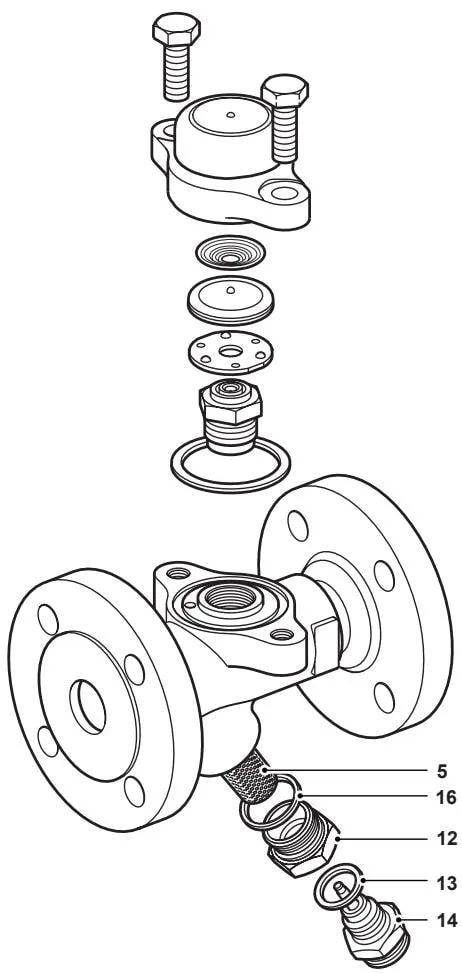
Fig. 6b
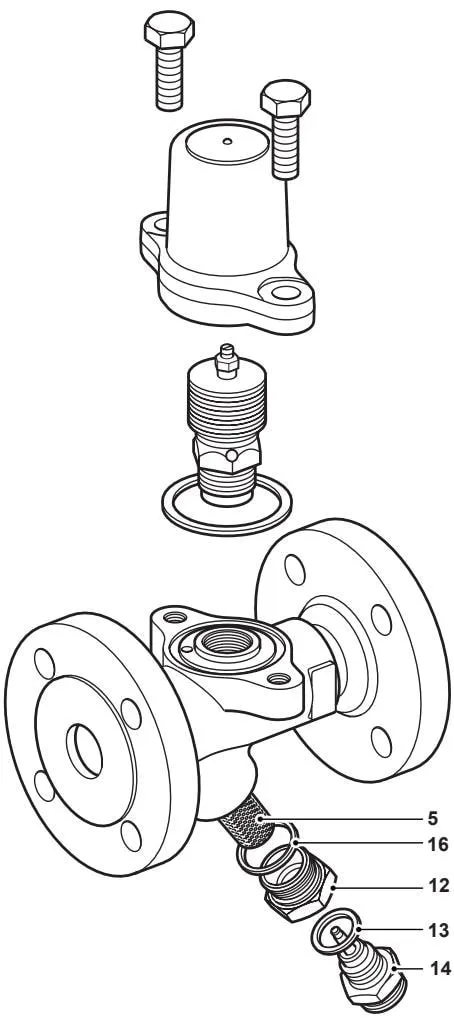
Fig. 7b
7. Spare parts
Available spare parts are shown in bold outline. Parts drawn with grey lines are not supplied as spare parts.
Available spare parts
| Capsule and seat assembly kit - IBPC32, IBPC32CV, IBPS32 and IBPS32CV | 2, 3, 17, 18 |
| Element set - ISMC32 | 2, 3, 4, 6 |
| Warning: Do not disassemble the element set by removing the lock-nut (4), as this will affect the trap setting. | |
| Y-type cylindrical strainer screen and gasket (1 each) | 5, 16 |
| Cover gasket set (3 per pack) | 7 |
| Sensor and sensor gasket | 13, 14 |
| Connector gasket (3 per pack) | 16 |
IBPC32, IBPC32CV, IBPS32 and IBPS32CV
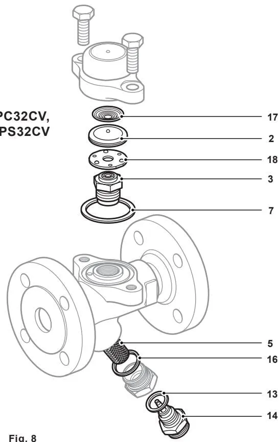
Fig. 8
How to order spare parts
When ordering spare parts, always use the description in the “Available spare parts” column and specify the size, model and capsule reference number.
Example 1: 1 capsule and seat assembly kit for a Spirax Sarco DN25 IBPC32, with a capsule filled with “STD” fill, operating at 12 °C below saturated steam temperature, with an integral Spiratec sensor.
Example 2: 1 element set for a Spirax Sarco DN25 ISMC32 bimetallic steam trap, with an integral Spiratec sensor.