1. Safety Information Guide
Please observe the relevant safety information guide supplied with the product, as well as national or local regulations.
Before installation or maintenance, ensure that the boiler is drained and vented to atmosphere.
To ensure safe operation, this product must be correctly installed, commissioned, and maintained by qualified personnel in accordance with the operating instructions.
Pipeline and plant installation and safety guidelines must be observed, together with the use of suitable tools and the necessary safety equipment.
The design and construction of this product are intended to withstand the pressures encountered during normal use. Using the product for any other purpose, or installing it incorrectly without following the installation and maintenance instructions, may damage the product, invalidate CE compliance, and result in personal injury.
2. Product Description
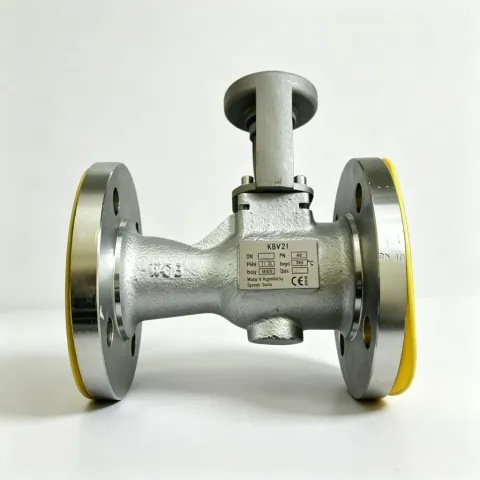
The KBV21 manual boiler blowdown valve is a carbon steel ball valve comprising a reinforced PFTE seat, stainless steel ball, connector, and valve sleeve. Two handle types are available: a standard-length handle and an extended ‘T’ handle for operating blowdown valves where space is restricted.
Note: To comply with boiler regulations, the manual handle cannot be removed when the valve is open.
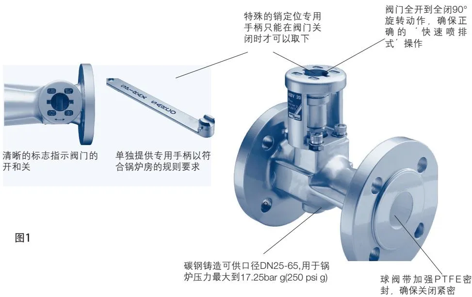
Figure 1
2.1 Limiting Conditions
Maximum allowable pressure: 17.25 bar g at 208°C. (Maximum allowable pressure: 250 psi g at 406°F.)
3. Installation
Note: Before carrying out any installation work, read Section 1, ‘Safety Information Guide’.
Check that the blowdown valve and inlet pipe sizes match. Ensure the pipe is of the correct length and aligned with the valve centreline to prevent stress. The valve must be installed with the flow direction as indicated by the arrow.
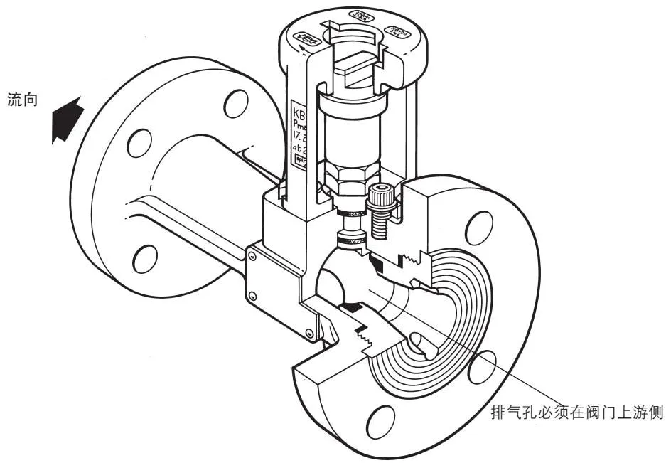
Figure 2
3.1 Removing the Valve Sleeve
Close the blowdown valve, then loosen the socket head cap screws and gasket (7/32 in. or 5/16 in. A/F).
Remove the valve sleeve and connector.
3.2 Installing the Handle Assembly
- Ensure that the valve is in the closed position. (If an operating handle is fitted, it should be at 90° to the valve centreline.)
- Remove the stem nut (7/8 in. A/F), spring washer, and operating handle, if fitted.
- Remove the stop bolt (1/2 in. or 7/8 in. A/F), if fitted.
- Check that the gland nut torque is 24-30 Nm (18-22 lbf ft).
- Fit the locknut (7/8 in. A/F) to prevent the gland nut from loosening.
- For DN25 and DN32 models, fit the locknut as described above.
- Place the connector into the valve sleeve and align the internal slot in the connector with the valve stem. Ensure that the threaded hole in the valve body is aligned with the cut-out in the valve sleeve.
- Fit the gasket and socket head cap screws (7/32 in. or 5/16 in. A/F). Tighten, then turn a further 1/4 turn.
- Insert the operating handle (supplied separately) and check that it can only be removed when the valve is closed.
4. Maintenance
Note: Before carrying out any maintenance work, read Section 1, ‘Safety Guide’.
It is recommended that the valve be inspected for debris and corrosion during boiler maintenance. Check the valve stem for leakage. If minor leakage is present, tighten the gland nut to 24-30 Nm (18-22 lbf ft).
Warning: A ball valve may trap the pressure of the medium within the valve cavity. Therefore, before loosening and removing flange bolts, ensure that the valve inlet, outlet, and interior are depressurised.
If the valve requires re-lapping, or is simply being dismantled for inspection, a special tool is required to remove the screwed insert. This tool can be made from steel plate of suitable thickness with rounded corners, and inserted into the corresponding holes in the packing.
The complete valve may be returned to Spirax Sarco for servicing.
When used for blowdown service, carbon-filled reinforced PFTE stem packing should be used instead of graphite packing.
4.1 Removing the Valve
Remove the handle assembly as described in 3.1.
4.2 Dismantling the Valve Body
As described in Section 4, use the special tool to remove the insert contained in the valve. Considerable force may be required to release the joint; use a vice if necessary.
Penetrating oil may be used to assist in removing the packing, but heating must not be used (see warning below).
Warning: If aged fluorocarbon O-rings are exposed to temperatures of 315°C (599°F) or above, they may decompose and produce hydrofluoric acid. Avoid skin contact with and inhalation of any fumes, as this acid may cause burns and damage to the respiratory system.
Once the insert has been removed, the ball can be taken out. To remove the valve stem, first loosen the locknut and gland nut, then gently tap the stem into the valve body using a soft-faced hammer to avoid damaging the stem threads.
4.3 Preparation
If necessary, use a soft metal scraper to remove all old packing. Note the quantity and position of the stem packing. The lower packing must be removed from the valve sleeve; take care not to scratch the rear surface. Ideally, the internal surfaces of the casting should be smooth and degreased, with all rust and deposits removed. The ball and valve stem must also be cleaned. If the valve stem has failed, it must be replaced.
4.4 Reassembling the Valve
Fit the required number of stem packing rings onto the valve stem and carefully insert it into the valve body casting to avoid damaging the holes in the stem. Fit the upper stem packing and press it down into the packing chamber. Fit the packing ring, Belleville spring washer, if fitted, and gland nut. Tighten the gland nut so that the stem protrudes and the stem packing is secured. Fit a new valve seat and insert the steel ball.
Note: The vent hole must be on the upstream side of the valve (see Figure 1).
Ensure that the ball is positioned at the end of the valve stem. Fit new packing of the type previously used, and compress the packing until the lower end is exposed. Tighten the gland nut to 24-30 Nm (18-22 lbf ft), or until the Belleville spring washer becomes flat, if fitted.
4.5 Testing
Ensure that the valve stem rotates freely without excessive friction. Carry out appropriate seat leakage and valve body hydrostatic tests.
| Seat leakage test | 6 barg | (87 psi g) | (air under water) |
| Cold hydrostatic test | 60 barg | (870 psi g) | (PN40) |
| 78 barg | (1131 psi g) | (Class 300) |
4.6 Assembly
Reassemble the handle assembly as described in Section 3.2. If a new valve body assembly has been purchased, it may be necessary to increase the diameter of the hole in the valve chamber to clear the Belleville spring washer.
5. Spare Parts
A complete spare parts kit is available, including all packing, gasket assemblies, and the valve ball.
Note: The vent hole in the ball must be on the upstream side of the valve (see Figure 1).
Valve stem spare parts are also available.
When ordering, please specify the valve type, application, such as boiler blowdown, and size (DN).
Example: 1 set of Spirax Sarco KBV21 boiler blowdown valve spare parts kit, DN50, PN40.