- Safety Information
- Product Information
- Installation
- Commissioning
- Operation
- Maintenance
- Spare Parts
1. Safety Information
Safe operation of this product can only be guaranteed if it is properly installed, commissioned, and maintained by qualified personnel (see Section 11 of the accompanying supplementary safety information) in accordance with the operating instructions. General installation and safety instructions for pipeline and plant construction must also be observed, together with the correct use of tools and safety equipment.
Warning
The cover gasket contains a thin stainless steel support ring, which may cause personal injury if handled or disposed of incorrectly.
Isolation
Consider whether closing isolation valves could expose other parts of the system or personnel to risk. Hazards may include isolation of vents or protective devices, or the malfunction of alarms. Ensure that isolation valves are opened and closed slowly to avoid system shock.
Pressure
Before carrying out any maintenance, consider what is or may have been in the pipeline. Ensure that any pressure is isolated and safely vented to atmospheric pressure before servicing the product. This can be easily achieved by fitting a Spirax Sarco DV pressure relief valve (see separate literature). Never assume that the system has been depressurized, even when a pressure gauge indicates zero.
Temperature
After isolation, allow sufficient time for the temperature to return to normal to avoid the risk of burns, and consider whether protective clothing, including safety glasses, is required.
Disposal
This product is recyclable. No ecological hazard is anticipated with proper disposal.
2. Product Information
2.1 General Description
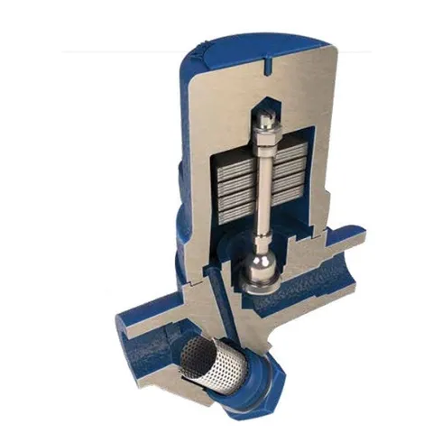
The Spirax Sarco SM45 is a medium-pressure, temperature-sensitive, maintainable steam trap. Its operating element consists of a set of bimetallic plates that control condensate flow at a preset temperature below saturated steam temperature.
Note: For further information, see Technical Information Sheet TI-P025-01.
2.2 Sizes and Pipeline Connections
1/2”, 3/4”, 1” and 1 1/2” screwed BSP or NPT connections.
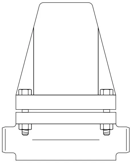
1/2”, 3/4”, 1” and 1 1/2” butt weld connections to suit Schedule 80 pipe, socket weld connections to BS 3799 Class 3000.
DN15, 20, 25 and 40 standard flanges to DIN 2546 PN64, ANSI 300, ANSI 600 and JIS / KS 30K.
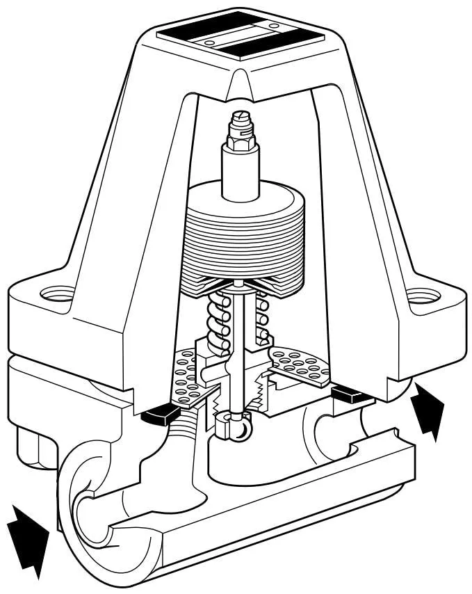
Figure 1 SM45 Butt Weld Connection Type
2.3 Limits (to ISO 6552)
| Maximum body design conditions | PN63 | ||
| PMA - Maximum allowable pressure | 63 bar g | (913.5 psi g) | |
| TMA - Maximum allowable temperature | 450 °C | (842 °F) | |
| PMO - Maximum operating pressure | 45 bar g | (652.5 psi g) | |
| TMO - Maximum operating temperature | 450 °C | (842 °F) | |
| Maximum design cold hydraulic test pressure: | PN64 flanged, screwed, socket weld and butt weld | 109 bar g | (1 581 psi g) |
| ANSI 300 flanged | 80 bar g | (1 160 psi g) | |
| ANSI 600 flanged | 109 bar g | (1 581 psi g) | |
| JIS / KS 30K flanged | 79 bar g | (1 145.8 psi g) | |
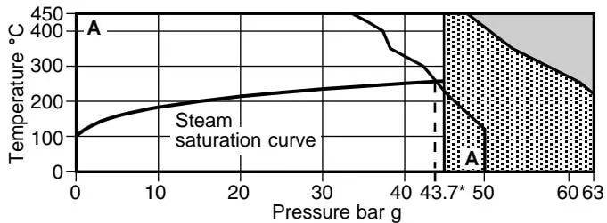
2.4 Operating Range
Screwed, socket weld, butt weld and JIS / KS 30K flanged
ANSI 300, ANSI 600 and PN64 flanged
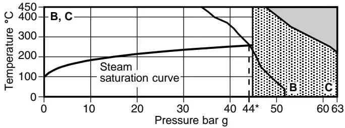

This product must not be used in this region.

This product should not be used in this region, as internal parts may be damaged.
*PMO Recommended maximum operating pressure at saturated steam conditions.
A - A Screwed, socket weld, butt weld and JIS / KS 30K flanged.
B - B ANSI 300 flanged.
C - C ANSI 600 and PN64 flanged.
3. Installation
Note: Before carrying out any installation, observe the “Safety Information” in Section 1.
Refer to the installation and maintenance instructions, nameplate, and technical information sheet to ensure that the product is suitable for the intended installation:
3.1 Check the materials, pressure and temperature ratings, and their maximum values. If the maximum operating limit of the product is lower than that of the system in which it is installed, ensure that a safety device is included in the system to prevent overpressure.
3.2 Determine the correct installation position and fluid flow direction.
3.3 Remove protective covers from all connections.
3.4 The trap is designed for installation with the element horizontal and the cover at the top.
3.5 When arc welding the trap into the pipeline, it is not necessary to remove the element.
3.6 Bimetallic steam traps are recommended for applications where condensate may be allowed to cool before discharge. Therefore, where prompt condensate drainage is required, a suitable uninsulated cooling leg must be installed immediately upstream of the trap. The cooling leg should be at least 1 - 2 m (3 - 6 ft) long.
Note: If the trap discharges to atmosphere, ensure that discharge is to a safe location. The discharged fluid may reach temperatures of up to 100 °C (212 °F).
4. Commissioning
After installation or maintenance, ensure that the system is fully operational. Test any alarm or protective devices.
5. Operation
The Spirax Sarco SM45 is a bimetallic steam trap. It operates on two opposing forces acting on the valve: an opening force generated by system pressure and a closing force generated by the effect of condensate temperature on the bimetallic element. The SM45 operates without steam loss and automatically provides rapid discharge of air, non-condensable gases, and large quantities of cold water during start-up.
6. Maintenance
Note: Before carrying out any maintenance procedure, observe the “Safety Information” in Section 1.
Warning
The cover gasket contains a thin stainless steel support ring, which may cause personal injury if handled or disposed of incorrectly.
6.1 General Information
Before carrying out any maintenance on the trap, it must be isolated from the supply and return pipelines, and any pressure must be safely reduced to atmospheric pressure. The trap should then be allowed to cool. When reassembling, ensure that all joint faces are clean.
6.2 How to Fit the Element Set
- Unscrew the cover nuts (11) and remove the cover from the body.
- Unscrew the element set (3) and replace it with a new element set. Apply a non-flowing silicone sealant, such as Loctite Superflex White Silicone Sealant, to the seat threads.
- Apply a light coating of suitable jointing compound to the seat gasket (6).
- Refit the cover and cover gasket (10), ensuring that the strainer (4) is correctly positioned.
- Ensure that the cover nuts are evenly tightened to the recommended torque (see Table 1).
Warning
Do not dismantle the element by removing the locknut (2), as this will cause the trap setting to be lost.
7. Spare Parts
Available spare parts are shown in heavy outline. Parts shown in broken outline are not supplied as spares.
Available Spare Parts
Element set (including valve plug, seat and seat gasket)
3, 6, 7
Strainer (pack of 3)
4
Gasket set (pack of 3 each)
6, 10
Important Note
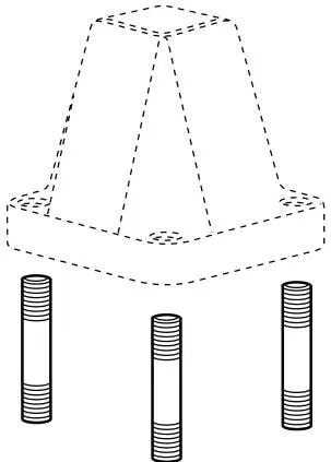
Early SM45 designs used four long cover studs, eight washers, and nuts to assemble the body and cover.
The current SM45 design uses a threaded cover, four shorter studs, and four washers and nuts.
How to Order Spare Parts
When ordering spare parts, always use the description given in the “Available Spare Parts” section and state the size and model of the trap.
Example: 1 - Element set for a Spirax Sarco DN25 SM45 bimetallic steam trap.
Warning
Do not dismantle the element by removing the locknut (2), as this will cause the trap setting to be lost.
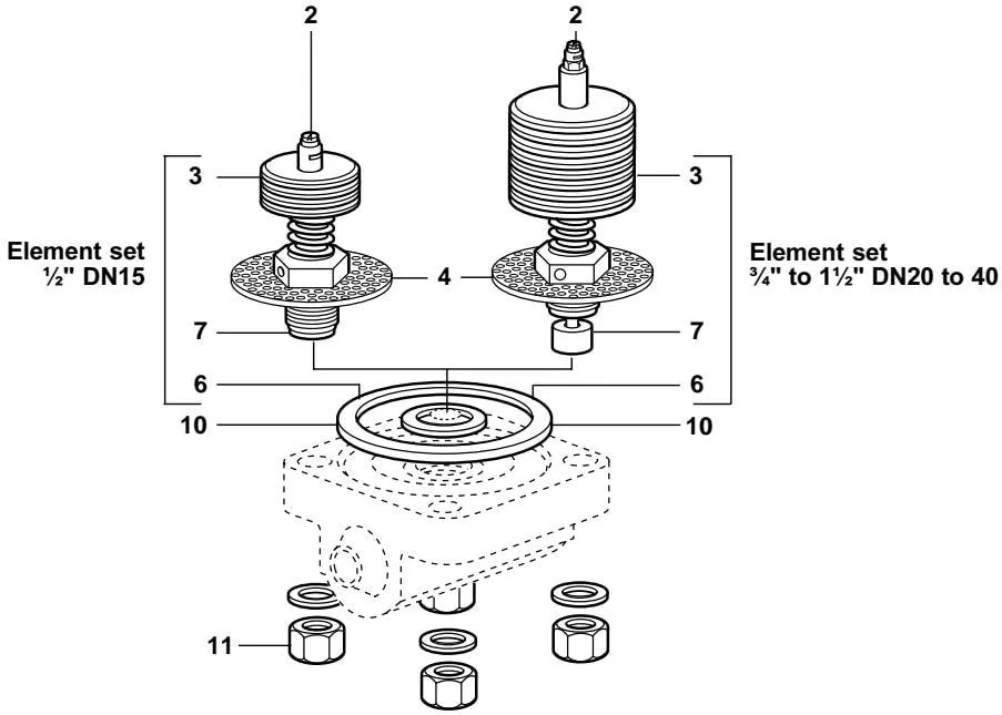
Figure 2 SM45 Butt Weld Connection Type
Table 1 Recommended Tightening Torques
| Item No. | Part |  | or mm | N m | (lbf ft) |
| 3 | Element | 27 A/F | 120 - 132 | (89 - 97) | |
| 11 | Cover nut | 19 A/F | M12 | 110 - 120 | (81 - 89) |