- Safety information
- Product information
- Installation
- Commissioning
- Operation
- Maintenance
- Spare parts
- Troubleshooting
1. Safety information
Safe operation of this product can only be guaranteed if it is properly installed, commissioned, used and maintained by qualified personnel in accordance with these operating instructions (see Section 1.11). The general installation and safety requirements for pipeline and plant construction, as well as the proper use of tools and safety equipment, must also be complied with.
1.1 Intended use
Refer to the Installation and Maintenance Instructions, name-plate and Technical Information Sheet to check that the product is suitable for the intended use/application.
This product complies with the requirements of the European Pressure Equipment Directive 2014/68/EU and carries the Ⓒ mark where required.
This product falls within the following categories of the Pressure Equipment Directive:
| Product | Group 2 gases | Group 2 liquids |
| USM21 | SEP | SEP |
i) This product has been specifically designed for use with steam, air or water/condensate in Group 2 of the above-mentioned Pressure Equipment Directive.
ii) Check material suitability and the maximum and minimum pressure and temperature values. If the maximum operating limits of the product are lower than those of the system in which it is installed, or if product failure could result in dangerous overpressure or overtemperature, ensure that a safety device is included in the system to prevent such excessive conditions.
iii) Determine the correct installation location and the direction of fluid flow.
iv) Spirax Sarco products are not intended to withstand external stresses that may be induced by the system in which they are installed. It is the responsibility of the installer to consider these stresses and take adequate precautions to minimise them.
v) Before installation in steam or other high-temperature applications, remove protective covers from all connections and, where applicable, remove protective film from all name-plates.
1.2 Access
Ensure safe access before working on the product and, if necessary, provide a suitably protected working platform. If lifting is required, arrange suitable lifting equipment.
1.3 Lighting
Ensure that adequate lighting is provided, particularly where detailed or complex work is required.
1.4 Hazardous liquids or gases in the pipeline
Consider what is currently in the pipeline or what may previously have been in it. Consider: flammable materials, substances hazardous to health and extreme temperatures.
1.5 Hazardous environment around the product
Consider: areas at risk of explosion, oxygen-deficient environments such as tanks or pits, hazardous gases, extreme temperatures, hot surfaces, fire hazards such as welding, excessive noise and moving machinery.
1.6 The system
Consider the effect of the proposed work on the entire system. Could any proposed action, such as closing isolation valves or switching off electrical isolation, put any other part of the system or personnel at risk?
Hazards may include the isolation of vents or protective devices, or the disabling of controls or alarms. Isolation valves should be opened and closed slowly to avoid system shock.
1.7 Pressure systems
Ensure that all pressure is isolated and safely vented to atmospheric pressure. Consider double isolation, including isolating and venting through two valves, and lock or tag closed valves. Do not assume that the system has been depressurised even when the pressure gauge indicates zero.
1.8 Temperature
After isolation, allow sufficient time for the temperature to return to normal to avoid the risk of burns.
1.9 Tools and consumables
Before starting work, ensure that suitable tools and/or consumables are available. Use only genuine Spirax Sarco spare parts.
1.10 Protective clothing
Consider whether you and/or others nearby require protective clothing to protect against hazards from chemicals, high or low temperatures, radiation, noise, falling objects, and eye and face hazards.
1.11 Permits to work
All work must be carried out by suitably competent personnel or under their supervision. Installation and operating personnel should be trained in the correct use of the product in accordance with the Installation and Maintenance Instructions.
Where a formal “permit to work” system is in operation, it must be complied with. Where no such system exists, it is recommended that a responsible person knows what work is being carried out and, where necessary, arranges for an assistant whose primary responsibility is safety.
If necessary, display “warning notices”.
1.12 Handling
Manual handling of large and/or heavy products may present a risk of injury. Lifting, pushing, pulling, carrying or supporting loads by bodily force can cause injury, particularly to the back. You are advised to assess the risks, taking into account the task, the individual, the load and the working environment, and to use an appropriate handling method according to the circumstances of the work being carried out.
1.13 Residual hazards
During normal use, the external surface of the product may become very hot. If used at the maximum permitted operating conditions, the surface temperature of the product may exceed 450 °C (850 °F).
This product does not drain itself. Take particular care when dismantling or removing the product from an installation (see the Maintenance Instructions).
1.14 Freezing
Provision must be made to protect products that are exposed to temperatures below freezing point and cannot drain themselves.
1.15 Disposal
Unless otherwise stated in the Installation and Maintenance Instructions, this product is recyclable and no ecological hazard is anticipated from its disposal, provided that appropriate care is taken.
Where additional information is not provided on the Spirax Sarco compliance web pages, this product can be safely recycled and/or disposed of, provided that it is handled carefully. Always comply with local recycling and disposal regulations.
1.16 Returning products
Customers and stockists are reminded that, under European Community health, safety and environmental laws, when returning products to Spirax Sarco they must provide information about any hazards and the precautions to be taken due to contamination residues or mechanical damage that may present health, safety or environmental risks. This information must be provided in writing, including health and safety data sheets relating to any substances identified as hazardous or potentially hazardous.
2. Product information
2.1 Description
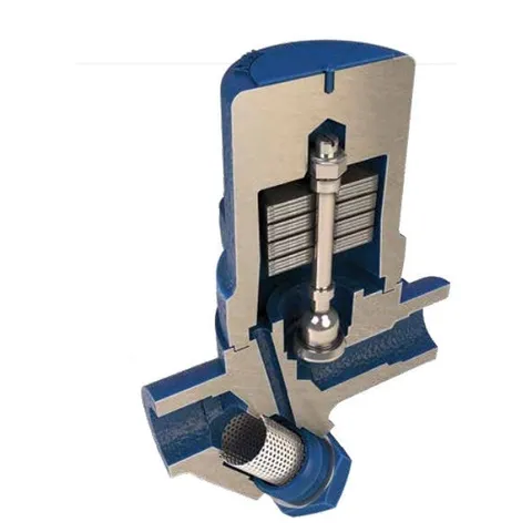
The USM21 is a pre-set, maintenance-free, sealed bimetallic steam trap manufactured from stainless steel. It is designed for steam pressures up to 21 bar and applications including steam tracing and main drainage. When fitted with a suitable pipe connector and installed in any position, the USM21 can be easily and simply removed without breaking the pipeline, speeding up trap replacement and minimising downtime. Pipe connectors are available with screwed, socket weld and flanged connections.
Standards
Body/cover welds comply with ASME Section IX and BS EN 288.
This product fully complies with the requirements of the European Pressure Equipment Directive 2014/68/EU and carries the Ⓒ mark where required.
Certification
This product is available with EN 10204 3.1 certification.
Note: All certification/inspection requirements must be stated at the time of ordering.
2.2 Sizes and pipe connections
The USM21 can be installed with a range of different pipe connectors, including:
| PC10 | In-line connector | ASME / ANSI 300 | (TI-P128-10) |
| PC10HP | In-line connector | ASME / ANSI 600 | (TI-P128-10) |
| PC20 | In-line connector with strainer | (TI-P128-15) | |
| IPC20, IPC21 | In-line connector with strainer or Spiratec sensor | (TI-P128-17) | |
| PC3 | Connector with one piston isolation valve | ASME / ANSI 600 | (TI-P128-02) |
| PC4 | Connector with two piston isolation valves | ASME / ANSI 600 | (TI-P128-03) |
Note: For details of the connections available for the pipe connectors, see the relevant Technical Information Sheet listed above.
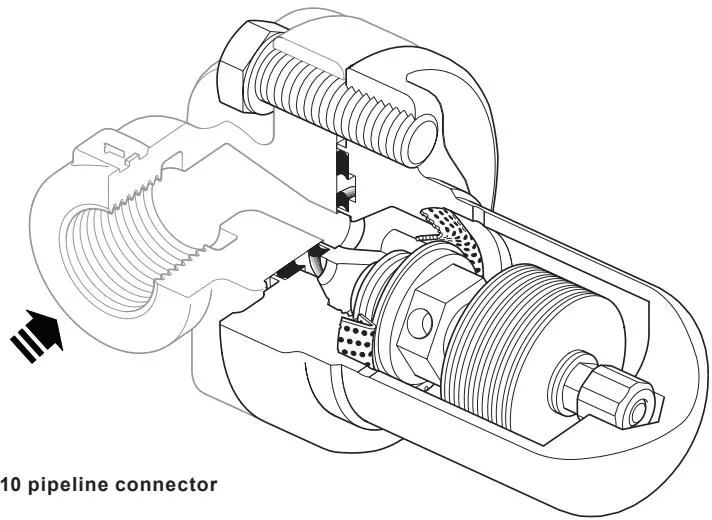
Fig. 1 USM21 connected to a PC10 pipe connector
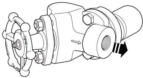
Fig. 2 USM21 connected to a PC3 pipe connector
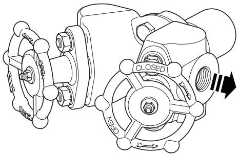
Fig. 3 USM21 connected to a PC4 pipe connector
2.3 Pressure/temperature limits
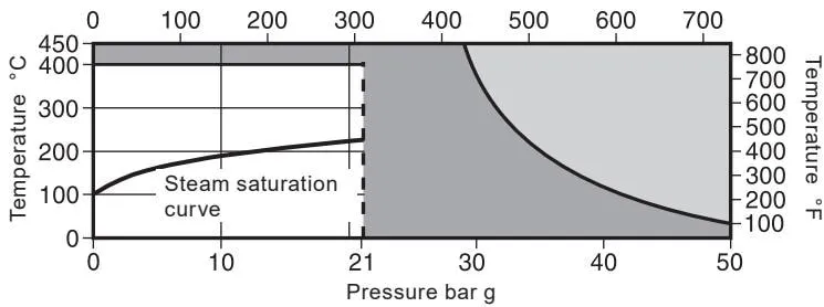
The product must not be used in this region.
The product should not be used in this region or beyond its operating range, as this may cause damage to internal components.
Note: The selected pipe connector model and connection type determine the maximum operating pressure and temperature of the complete assembly. Refer to the relevant Technical Information Sheet listed in the section “Sizes and pipe connections” for the applicable data.
| Body design conditions | ANSI/ASME 300 | ||
| PMA | Maximum allowable pressure | 50 bar g @ 40 °C | 725 psi g @ 104 °F |
| TMA | Maximum allowable temperature | 450 °C @ 29 bar g | 842 °F @ 420 psi g |
| Minimum allowable temperature | -29 °C | -20 °F | |
| PMO | Maximum operating pressure for saturated steam service | 21 bar g | 304 psi g |
| TMO | Maximum operating temperature | 400 °C @ 21 bar g | 752 °F @ 304 psi g |
| Minimum operating temperature | 0 °C | 32 °F | |
| ΔPMX | Maximum differential pressure | 21 bar g | 304 psi g |
| Design maximum cold hydraulic test pressure | 75 bar g | 1 087 psi g | |
The trap is available with a range of subcooling temperature settings. Except during start-up and shutdown, the operating differential pressure of the trap must be higher than the minimum differential pressure shown in the table below:
| Nominal subcooling temperature | External marking | Threshold differential pressure |
| -10 °C (14 °F) | "-1" | 5 bar g (72.51 psi g) |
| -30 °C (-22 °F) | "-3" | 2 bar g (29.00 psi g) |
| -50 °C (-58 °F) | "-5" | 0.5 bar g (7.25 psi g) |
| -70 °C (-94 °F) | "-7" | 0.1 bar g (1.45 psi g) |
3. Installation
Note: Before carrying out any installation work, observe Section 1, “Safety information”.
Refer to the Installation and Maintenance Instructions, name-plate and Technical Information Sheet to verify that the product is suitable for the intended installation conditions:
3.1 Check the materials, pressure and temperature, including their maximum values. If the product’s maximum operating limits are lower than those of the system, ensure that the system includes a safety device to prevent overpressure.
3.2 Determine the correct installation position and fluid flow direction.
3.3 Remove all protective covers from the connections.
3.4 Install the pipe connector and steam trap downstream of the equipment being drained, ensuring adequate access for inspection and maintenance.
3.5 USM21 can be installed on any pipe connector in any plane. For the Installation and Maintenance Instructions for Spirax Sarco pipe connectors, refer to the separate documents (PC3/PC4 pipe connector Installation and Maintenance Instructions, PC20, IPC20 and IPC21 pipe connector Installation and Maintenance Instructions and PC10HP pipe connector Installation and Maintenance Instructions).
3.6 When installing the trap, the arrow on the body must point in the direction of fluid flow.
3.7 For socket-weld traps, a qualified welding procedure complying with the relevant national and international welding standards must be followed. The trap does not need to be removed from the PC connector during welding provided that an arc-welding method is used. Avoid overheating.
3.8 Ensure that both gasket surfaces are clean and that the passage holes are clear. Position the trap against the connector and fit the connector bolts (11). Ensure that a small amount of anti-seize compound is applied to the bolt threads. Tighten the bolts finger-tight, ensuring that the trap/connector mating surfaces are parallel, then tighten to the specified torque given in Table 1 (page 11).
3.9 Slowly open the isolation valve until normal operating conditions are reached.
3.10 Check for leaks.
Note: If the trap discharges to atmosphere, ensure that the discharge is directed to a safe location, as the discharge fluid temperature may reach 100 °C (212 °F). Installing a diffuser downstream of the trap outlet is strongly recommended. This can reduce noise and erosion problems by buffering the high-velocity discharge flow. For further information, refer to TI-P155-02.
4. Commissioning
After installation or maintenance, ensure that the system is fully operational. Test all alarms or protective devices.
5. Operation
The Spirax Sarco USM21 is a sealed bimetallic steam trap designed for use with any Spirax Sarco PC series pipe connector.
The trap operates using two opposing forces acting on the valve: the opening force generated by system pressure and the closing force generated by the condensate temperature acting on the bimetallic element.
The USM21 operates without steam loss and automatically and rapidly discharges air, non-condensable gases and large quantities of cold water during start-up.
6. Maintenance
Note: Before carrying out any maintenance programme, observe Section 1, “Safety information”.
Warning
The inner and outer gaskets (9 and 10) used when installing or maintaining the USM21 and PC pipe connector contain thin stainless steel support rings which may cause personal injury if handled or disposed of incorrectly.
Safety information
These traps are installed in high-pressure steam lines. Personnel carrying out adjustment work should wear thick gloves, long-sleeved shirts and other personal protective equipment intended to protect the wearer, such as safety glasses and face shields, in case of leakage.
6.1 General information
All work must be carried out by suitably qualified personnel. Before performing any maintenance on the trap, it must be isolated from the steam supply and return lines on both sides, and all pressure must be safely released to atmospheric pressure. The trap should then be allowed to cool. During reassembly, ensure that all mating surfaces are clean.
6.2 Replacing the bimetallic trap unit
- Always use the correct tools and the necessary protective equipment.
- To replace the trap unit, remove the two connector bolts (11) and remove the trap unit.
- Position the new trap unit against the gasket face of the connector and apply a small amount of anti-seize compound to the connector bolt threads.
- Tighten the connector bolts (11) finger-tight, ensuring that the trap unit is parallel with the pipe connector.
- Tighten the connector bolts gradually to the recommended torque (see Table 1).
- Slowly open the isolation valve until normal operating conditions are reached.
- Check for leaks.
7. Spare parts
The USM21 is a sealed, maintenance-free trap unit, and no internal spare parts are available. Available spare parts are shown with solid outlines. Parts shown with grey lines are not available as spare parts.
Available spare parts
| Connector bolts (2 off) | 11 |
| Complete USM21 trap unit, including gaskets (9 and 10) and connector bolts (11) | |
Note: The gaskets contain sharp metal reinforcing rings. Handle them with care.
How to order spare parts
When ordering spare parts, always use the description given in the “Available spare parts” column and state the size and model of the steam trap.
Example: 2 - Connector bolts for the USM21 sealed bimetallic steam trap.
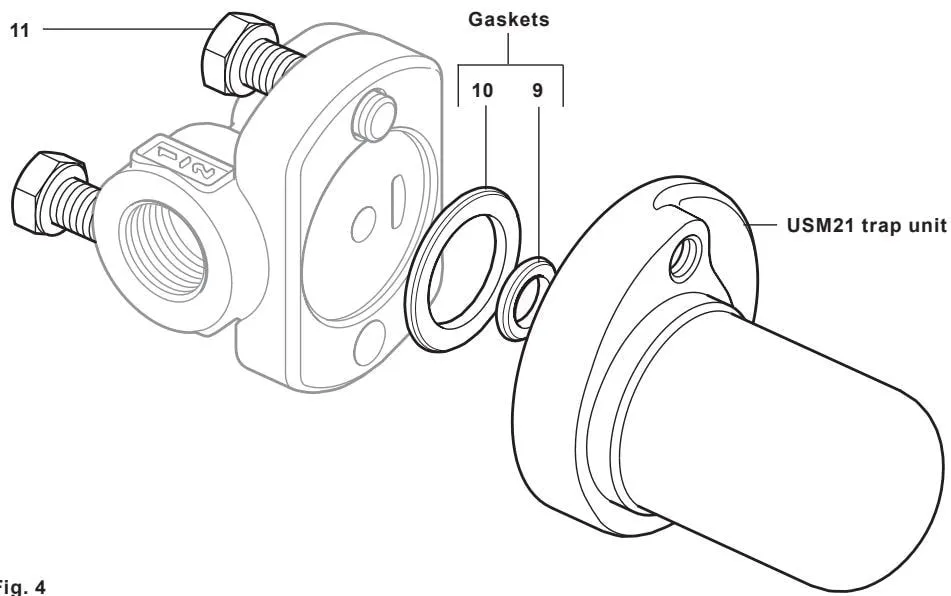
Figure 4
Table 1 Recommended tightening torques
| Item | Part |  or mm or mm |  | N m | (lbf ft) |
|---|---|---|---|---|---|
| 11 | Connector bolts | 9/16” A/F | 30 - 35 | (22 - 26) |
8. Troubleshooting
| Trap does not discharge condensate | 1. Ensure that both the upstream and downstream valves are open. |
| 2. Check whether the external strainer, such as PC20, is blocked; blow down or remove and clean it. | |
| 3. Back pressure is too high. The downstream system must be corrected. | |
| 4. The valve orifice is blocked by dirt. Remove, inspect and clean it. | |
| 5. The internal trap strainer is blocked by dirt, or the bimetallic element has failed. Replace the trap unit. | |
| Trap discharges a large amount of steam | 1. Dirt is present on the seating surfaces. Replace the trap unit. |
| 2. The bimetallic element has failed. Replace the trap unit. | |
| 3. The valve seat is worn. Replace the trap unit. | |
| Trap discharges condensate at a lower discharge temperature and lower drainage rate | 1. Back pressure may be too high. Try reducing the back pressure. If it cannot be reduced, replace the trap with a model having a lower subcooling temperature, as detailed in Section 2.3. |